5
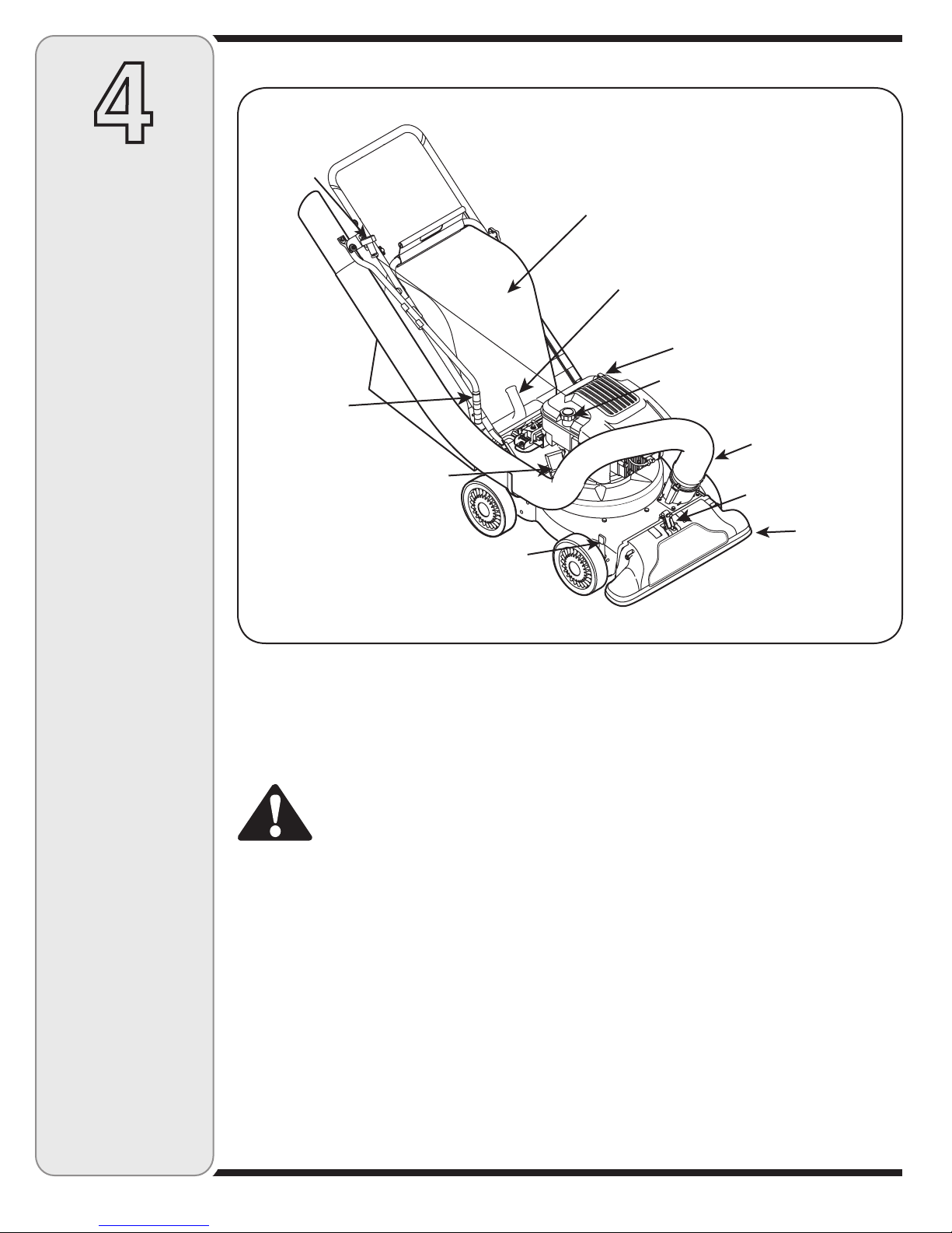
Operation
1. Do not put hands and feet near rotating parts or in the
feeding chambers and discharge opening. Contact with the
rotating impeller can amputate fingers, hands, and feet.
2. Before starting the machine, make sure the chipper chute,
feed intake, and cutting chamber are empty and free of all
debris.
3. Thoroughly inspect all material to be shredded and remove
any metal, rocks, bottles, cans, or other foreign objects
which could cause personal injury or damage to the
machine.
4. If the impeller strikes a foreign object or if your machine
should start making an unusual noise or vibration,
immediately shut the engine off. Allow the impeller to come
to a complete stop. Disconnect the spark plug wire, ground
it against the engine and perform the following steps:
a. Inspect for damage.
b. Repair or replace any damaged parts.
c. Check for any loose parts and tighten to assure
continued safe operation.
5. Do not allow an accumulation of processed material to build
up in the discharge area. This can prevent proper discharge
and result in kickback of material through the feed opening.
6. Do not attempt to shred or chip material larger than
specified on the machine or in this manual. Personal injury
or machine damage could result.
7. Never attempt to unclog either the feed intake or discharge
opening while the engine is running. Shut the engine off,
wait until all moving parts have stopped, disconnect the
spark plug wire and ground it against the engine before
clearing debris.
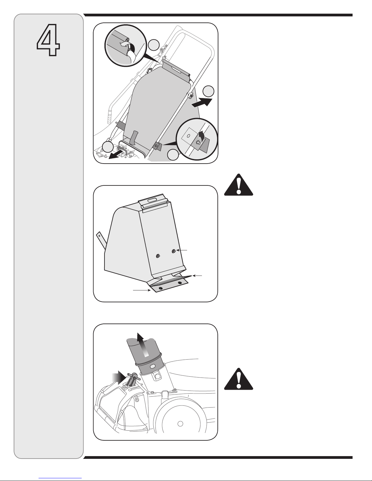
8. Never operate without vacuum bag and discharge chute
properly attached to the machine. Never empty or change
vacuum bag while the engine is running. Zippered end
of vacuum bag must be kept closed at all times during
operation.
9. Never operate without either the inlet nozzle or optional
hose attachment properly attached to the machine. Never
attempt to attach or change either attachment while the
engine is running.
10. Keep all guards, deflectors and safety devices in place and
operating properly.
11. Keep your face and body back and to the side of the chipper
chute while feeding material into the machine to avoid
accidental kickback injuries.
12. Never operate this machine without good visibility or light.
Always be sure of your footing and keep a firm hold on the
handles.
13. Do not operate this machine on a gravel surface.
14. Do not operate this machine while under the influence of
alcohol or drugs.
15. Muffler and engine become hot and can cause a burn. Do
not touch.
16. Never pick up or carry machine while the engine is running.
Maintenance & Storage
1. Never tamper with safety devices. Check their proper
operation regularly.
2. Check bolts and screws for proper tightness at frequent
intervals to keep the machine in safe working condition.
Also, visually inspect machine for any damage and repair,
if needed.
3. Before cleaning, repairing, or inspecting, stop the engine
and make certain the impeller and all moving parts have
stopped. Disconnect the spark plug wire and ground it
against the engine to prevent unintended starting.
4. Do not change the engine governor settings or overspeed
the engine. The governor controls the maximum safe
operating speed of the engine.
5. Maintain or replace safety and instruction labels, as
necessary.
6. Follow this manual for safe loading, unloading, transport-
ing, and storage of this machine.
7. Never store the machine or fuel container inside where
there is an open flame, spark or pilot light such as a water
heater, furnace, clothes dryer, etc.
8. Always refer to the operator’s manual for proper instruc-
tions on off-season storage.
9. If the fuel tank has to be drained, do this outdoors.
10. Observe proper disposal laws and regulations for gas, oil,
etc. to protect the environment.
Do not modify engine
To avoid serious injury or death, do not modify engine in any
way.Tampering with the governor setting can lead to a runaway
engine and cause it to operate at unsafe speeds. Never tamper
with factory setting of engine governor.
Notice regarding Emissions
Engines which are certified to comply with California and
federal EPA emission regulations for SORE (Small Off Road
Equipment) are certified to operate on regular unleaded gaso-
line, and may include the following emission control systems:
Engine Modification (EM) and Three Way Catalyst (TWC) if so
equipped.
Your Responsibility
Restrict the use of this power machine to persons who read,
understand and follow the warnings and instructions in this
manual and on the machine.
2
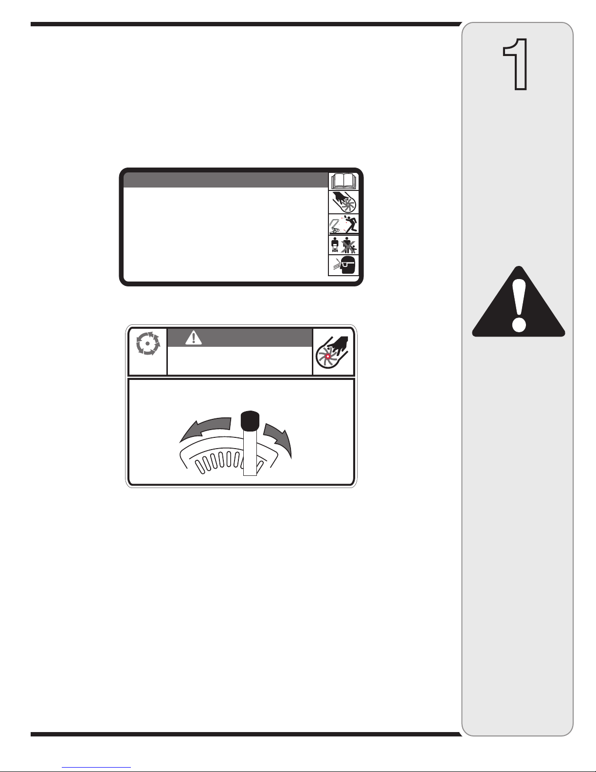
Safe
Operation
Practices
WARNING
This symbol points
out important safety
instructions, which if
not followed, could
endanger the personal
safety and/or property
of yourself and others.
Read and follow all
instructions in this man-
ual before attempting to
operate this machine.
Failure to comply with
these instructions may
result in personal injury.
When you see this
symbol.
HEED IT’S WARNING!
Your Responsibility
Restrict the use
of this power machine
to persons who read,
understand
and follow the warnings
and instructions
in this manual
and on the machine.