Version Januar 2011 DE 5
Bedienungsanleitung 2.00.339, 2.00.340
DÜPERTHAL Sicherheitstechnik GmbH & Co. KG
Frankenstr. 3
63791 Karlstein,
Deutschland
1 Einleitung
Sehr geehrter Kunde,
Wir danken für das in unser Produkt gesetzte Vertrauen und wünschen Ihnen
viel Erfolg und einen zufriedenen Arbeitsablauf.
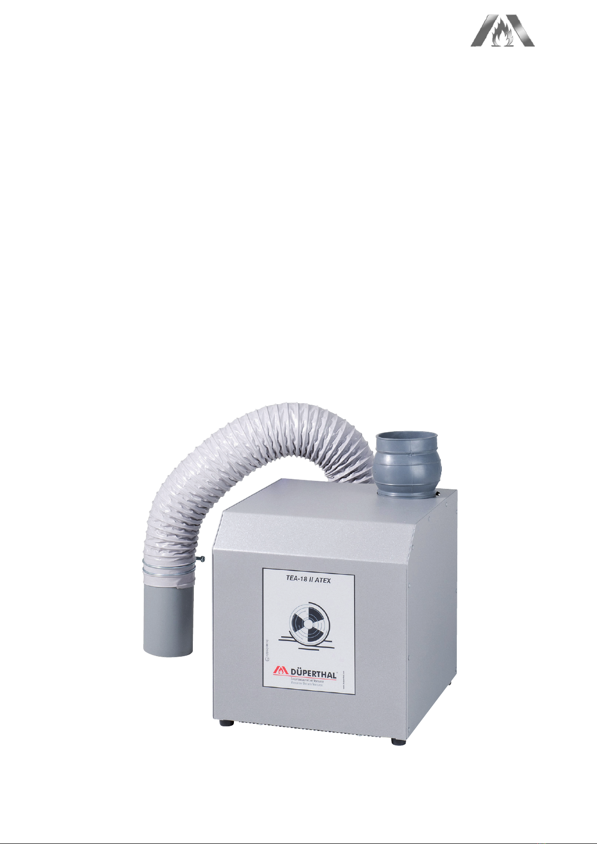
Bei der Entwicklung, Fertigung und Prüfung des ATEX‑konformen Entlüftungs‑
aufsatzes mit Ventilator haben wir größten Wert auf Betriebssicherheit und
Benutzerfreundlichkeit gelegt. Der Aufsatz ist nach dem neusten Stand der
Technik und nach anerkannten sicherheitstechnischen Regeln gefertigt und
geprüft worden. Er ist geeignet für den Einsatz in Bereichen mit explosionsfä‑
higen Atmosphären.
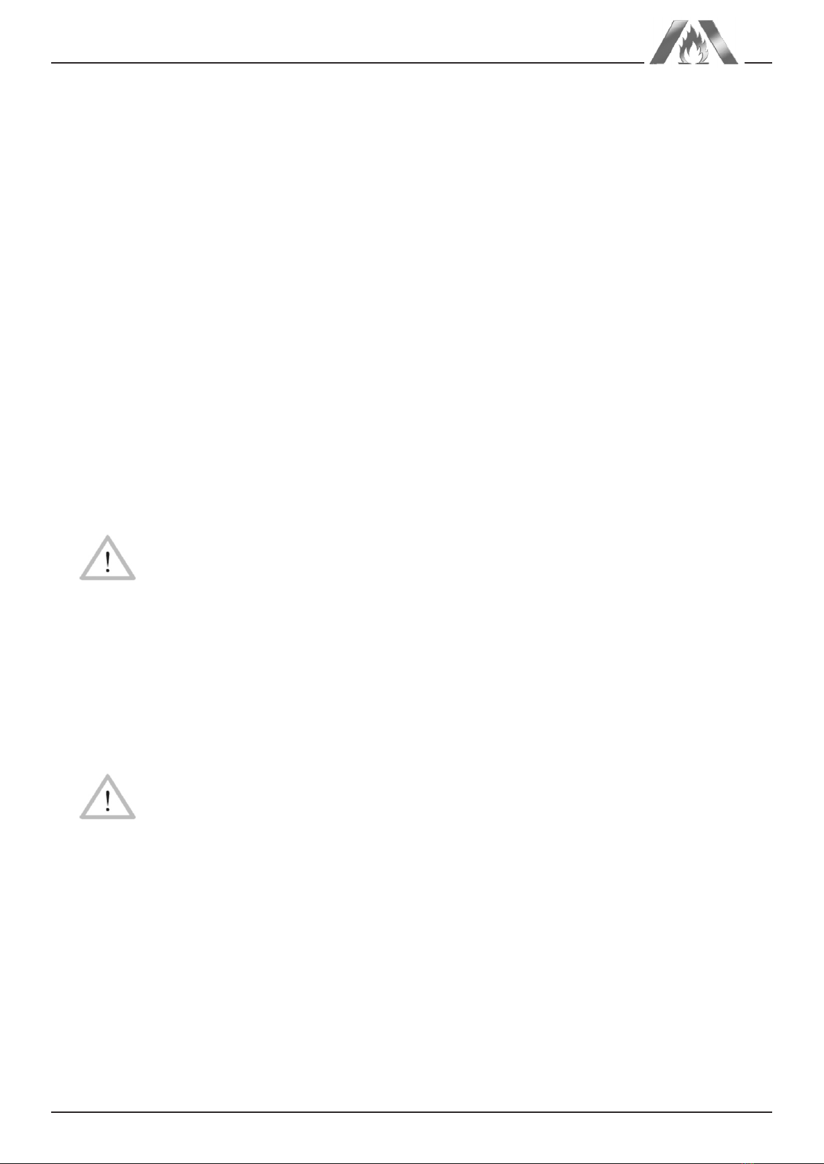
1.1 Bestimmungsgemäße Verwendung
Der Abluftaufsatz mit Ventilator muss in EX‑freien Bereichen aufgestellt werden
und dient ausschließlich der Entlüftung durch Absaugung von Sicherheits‑
schränken im Innenbereich, Zone 2 für Gase der Temperaturklassen T1 ‑ T4,
Gasgruppe IIA oder Gasgruppe IIB.Das Produkt ist nur geeignet für Gasströme,
die keine Partikel und Fremdstoffe transportieren. Die maximale Ansaugtem‑
peratur beträgt 50°C.
Es dürfen nur Stoffe abgesaugt werden, durch die die Saugmuffe aus PPs,
der Saugschlauch aus PVC und der Ventilator nicht beeinträchtigt werden. Die
entsprechende Stoffliste kann vom Hersteller in digitaler Form zur Verfügung
gestellt werden.
Vorsicht
JedeVerwendung, die andersartig als das oben Beschriebene ist, ist
verboten, kann zu gefährlichen Situationen, bis hin zur Lebensgefahr,
Schäden an Anlage und Sachwerten führen und lässt Gewährleistung
und Haftung für das Produkt seitens seines Herstellers und Vertrei‑
bers erlöschen.
1.2 Arbeitssicherheit
Bei Montage und Betrieb sind die Technischen Regeln zur Lagerung brennbarer
Flüssigkeiten, TRbF 20, Anhang L, die Norm EN 294 sowie alle anwendbaren
gesetzlichen Vorschriften stets zu beachten. Das Produkt stellt bauartbedingt
den Berührschutz für die Ventilatorflügel sicher. Veränderungen an Gehäuse
oder Ansaug‑ und Abluftschlauch, durch die die Ventilatorflügel im Betrieb
berührbar werden, sind verboten.
Vorsicht
Das Produkt darf nur fertig montiert, mit ordnungsgemäß angeschlos‑
senem Ansaug‑ und Abluftschlauch in Betrieb genommen werden.
Elektrische Arbeiten am Produkt dürfen nur vorgenommen werden,
wenn der Abluftaufsatz zuvor stromlos geschaltet bzw. der Netz‑
stecker gezogen wurde. Dasselbe gilt für elektrische Arbeiten am
Abluftüberwachungssystem, zu dem der Aufsatz eventuell gehört.
2 Montage der Einheit und Funktionsbeschreibung
2.1 Montage und Inbetriebnahme
1. Schließen Sie die bauseitige Abluftanlage oder den zu entlüftenden Si‑
cherheitsschrank an:
Verbinden Sie das externe Lüftungssystem oder den Abluftstutzen des
Schranks spannungsfrei, z.B.mit einer flexiblen Manschette, mit der Einheit
und dichten Sie die Verbindung mit einer passenden Schlauchschelle ab.
Dies ist zwingend notwendig, um eine einwandfreie Funktion des Lüfters