DÖRR Filter HP User manual

Information about the document
This document describes the correct han-
dling of the product.
Read the document prior to every activity.
Prepare the document for the application.
Pass on the product only together with
the complete documentation.
Always follow safety instructions, han-
dling instructions and specifications of
every kind.
Illustrations can deviate from the tech-
nical construction.
Validity range of the document
This document describes the following prod-
ucts:
N3543....
Filter HP
Hotline and Contact
If you have queries or would like technical
information, please contact your dealer or
sales partner.
01/2020Filter HP - MFT00003EN2/36

TABLE OF CONTENTS
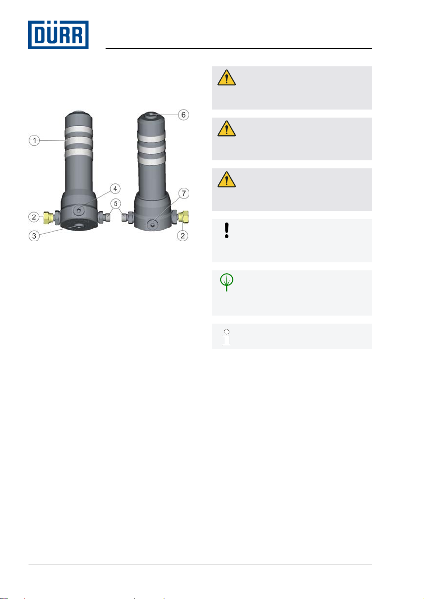
1 Product overview.......................... 4
1.1 Overview................................ 4
1.2 Short description.................... 4
2 Safety............................................. 4
2.1 Presentation of Notes............ 4
2.2 Intended Use.......................... 4
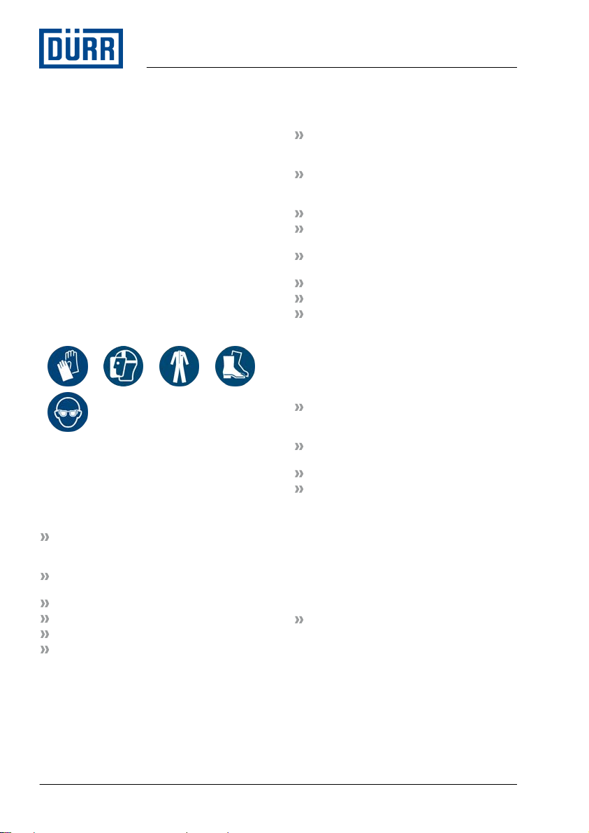
2.3 Staff qualification.................... 5
2.4 Personal protective equip-
ment....................................... 6
2.5 Residual risks......................... 6
3 Transport, scope of supply and
storage........................................... 6
3.1 Scope of delivery................... 6
3.2 Handling of
packaging material................. 7
3.3 Storage.................................. 7
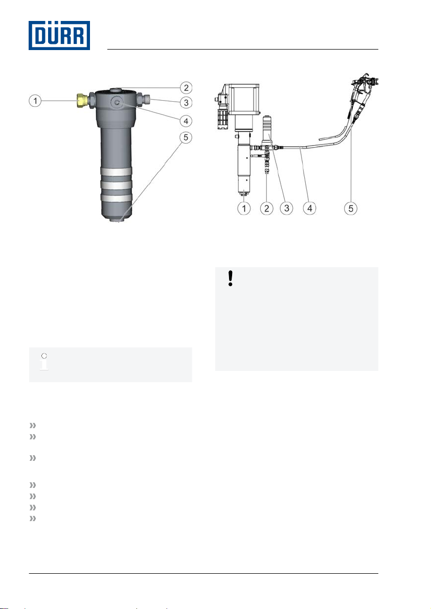
4 Assembly....................................... 7
4.1 Requirements for the
Installation point..................... 7
4.2 Installation position................ 7
4.3 Assembly............................... 8
4.4 Assemble pressure gage....... 9
5 Commissioning........................... 10
5.1 Safety Instructions............... 10
5.2 Check safety devices .......... 11
5.3 Commissioning..................... 11
6 Operation..................................... 11
6.1 Rinsing................................. 11
7 Cleaning....................................... 11
7.1 Safety recommendations .... 11
7.2 Cleaning............................... 12
8Maintenance................................ 12
8.1 Safety recommendations..... 12
8.2 Maintenance schedule......... 13
8.3 Dismantling.......................... 14
8.4 Assembly............................. 15
9 Faults........................................... 15
9.1 Defects table........................ 15
9.2 Troubleshooting................... 16
9.2.1 Replacing sealing ring....... 16
10 Disassembly and Disposal........ 16
10.1 Safety recommendations... 16
10.2 Disassembly....................... 17
10.3 Disposal ............................ 17
11 Technical data............................. 18
11.1 Dimensions and weight...... 18
11.2 Connections....................... 19
11.3 Operating conditions.......... 19
11.4 Operating values................ 19
11.5 Material specification.......... 19
11.6 Type plate........................... 19
11.7 Operating and auxiliary
materials............................. 19
11.8 Materials used.................... 19
12 Replacement parts and acces-
sories........................................... 20
12.1 Replacement parts............. 20
12.2 Accessories........................ 33
12.3 Order.................................. 33
01/2020 Filter HP - MFT00003EN 3/36

1 Product overview
1.1 Overview
Fig. 1: Overview (example)
1 Filter sump
2 Material inlet M 16 x 1.5, internal threads
3 Material outlet G1/4''
4 Material outlet G1/4''
5 Material outlet M 16 x 1.5, external
threads
6 Material outlet unfiltered G3/8''
7 Material outlet G1/4''
1.2 Short description
The high pressure filter (hereafter called
“Filter”) ensures in the supply line of an
application layer that no undesired particles
or impurities will arise in the subsequent
process flow. The filter is mounted between
the outlet of a high pressure pump and a
high pressure hose.
2 Safety
2.1 Presentation of Notes
The following notes can appear in this
instruction:
DANGER!
High risk situation that can lead to serious
injuries or death.
WARNING!
Medium risk situation that can lead to
serious injuries or death.
CAUTION!
Low risk situations that can lead to minor
injuries.
NOTICE!
Situations that can lead to material
damage.
ENVIRONMENT!
Situations that can lead to environmental
damage.
Additional information and recom-
mendations.
2.2 Intended Use
Use
The high pressure filter serves for the fine fil-
tration of liquids.
The high pressure filter is approved for use
in Ex zones 1 and 2. The fluids used must
conform to the explosion group IIB.
The high pressure filter is intended for use in
industry and trade only.
The high pressure filter may only be used
within the approved technical data Ä 11
“Technical data”.
Product overview
01/2020Filter HP - MFT00003EN4/36

The high pressure filter for fluids
does not fall in one of the categories
I - IV of the pressure devices guide-
lines. The high pressure filter is
designed and manufactured, as
specified in article 4 para 3 of
2014/68/EU.
Misuse
Not using as intended entails danger to life.
Examples of wrong use are:
Use of the high pressure filter with gases
and solids
Use of unapproved materials, see safety
data sheets
Use in explosive areas Ex zone 0
Making conversions or changes on your
own
Use of unsuitable components
Use of unapproved components
Ex labeling
II 2G Ex h IIB T6 Gb X
II - Device group II: all areas except
mining
2G - Device category 2 for gaseous
atmosphere
Ex h - Ignition protection category for non-
electrical devices
IIB - Explosion group IIB
T6 - Temperature class
Gb - Device protection level: Zone 1
X - Restriction: The device is configured
for operation in an ambient temper-
ature of -5°C to 50°C.
2.3 Staff qualification
WARNING!
Inadequate qualification
Wrong estimation of dangers can cause
serious injury or death.
– Only sufficiently qualified persons may
execute all work.
– Some work requires additional qualifi-
cation. Additional qualifications of spe-
cialized personnel are marked with a
“+”.
This document is intended for qualified per-
sonnel in industry and craftmanship.
Electrician
Electricians assemble, install, service and
repair electrical systems in a professional
manner.
Furthermore, electrical engineers have the
following knowledge:
Guidelines, Standards and Rules of Engi-
neering
Local conditions
Electrical Systems and Their Loading
Limits
Technical Measures for occupational
safety and health
Mechanic
The mechanic is trained specifically for the
field of work in which he works.
Furthermore, he has the following knowl-
edge:
Guidelines, Standards and Rules of Engi-
neering
Local conditions
Technical Measures for occupational
safety and health
The mechanic is responsible for the fol-
lowing activities on equipment and compo-
nents:
Assembly
Waiting
Maintenance
Disassembly
Safety
01/2020 Filter HP - MFT00003EN 5/36

+ Additional qualification high pressure
In addition, the mechanic has knowledge of
regulations and safety measures for high
pressure systems > 20 bar.
+ additional qualification explosion pro-
tection
In addition to the knowledge of the various
specialist fields, the mechanic has knowl-
edge of regulations and safety measures
when working in potentially explosive areas.
Dürr Systems offers special product training
for Ä “Hotline and Contact”.
2.4 Personal protective equipment
Wear the required personal protective equip-
ment when working. Provide the following
personal protective equipment:
2.5 Residual risks
Explosion
Sparks, open flames and hot surfaces can
cause explosions in explosive atmospheres.
It can cause serious injuries or death.
Before carrying out any work on the
product, ensure a non-explosive atmos-
phere.
Do not use sources of ignition and open
light.
Do not smoke.
Ground the product.
Ground the work piece.
Wear suitable protective equipment.
Flammable coating materials and their deter-
gents and cleaning agents can cause a fire
or an explosion.
Ensure that the flashpoint of the fluid is at
least 15K above the ambient tempera-
ture.
Observe explosion group of the coating
materials and their detergents and
cleaning agents.
Follow the safety data sheet.
Ensure that technical ventilation and fire
protection equipment are in operation.
Do not use sources of ignition and open
light.
Do not smoke.
Ground the product.
Wear suitable protective equipment.
Danger from harmful or irritant sub-
stances
Serious injuries or death can result if you
come into contact with dangerous fluids or
steam.
Filter Check regularly for leakage.
Observe local regulations and mainte-
nance schedule.
Ensure that the forced ventilation is
operational.
Follow the safety data sheet.
Wear specified protective equipment.
3 Transport, scope of supply
and storage
3.1 Scope of delivery
The scope of supply includes the following
components:
High pressure filter
1. Inspect delivery on receipt for complete-
ness and integrity.
2. Report defects immediately Ä “Hotline
and Contact”.
Transport, scope of supply and storage
01/2020Filter HP - MFT00003EN6/36

3.2 Handling of packaging material
ENVIRONMENT!
Incorrect disposal
Incorrectly disposed packaging material
can damage environment.
– Dispose of material no longer required
in an environment-friendly manner.
– Observe local disposal specifications.
3.3 Storage
Storage provisions:
Do not store outdoors.
Store Filter only when dry.
Store in a dust-free place.
Do not expose to aggressive media.
Protect from solar radiation.
Avoid mechanical vibrations.
Temperature: 10°C to 40°C
Relative humidity: 35% to 90%
4 Assembly
4.1 Requirements for the
Installation point.
It should be possible to disconnect every
power supply to the filter and secure it
against reconnection.
The air supply must be adjustable.
Lines, seals and screw connections must
be designed for the requirements of the
filter.
The filter must be accessible for mainte-
nance work.
Provide pressure release device to avoid
excess pressure.
4.2 Installation position
Install the filter vertically. The filter sump can
face up or down.
Filter sump upwards
Fig. 2: Installation on top (example)
1 Material inlet
The filter is used as compressor. Air presses
up in the filter and keeps the fill level con-
stant. Prevent pressure drops in the con-
nected product and minimize pulsations. Up
to four application devices can be connected
to the connections (2), (3).
If the filter sump is installed above, a
pressure relief valve must be
attached to a connection (2), (3).
Assembly
01/2020 Filter HP - MFT00003EN 7/36

Filter sump downwards
Fig. 3: Installation at bottom (example)
1 Material inlet
The filter can be used for circulation. Air
presses directly through the material outlet
(2) into the high pressure hose. Material run-
ning through the lateral material outlets (2),
(3), (4) is filtered. Material running through
the lower material outlet (5) circulates and is
not filtered. A pressure gage can be con-
nected to the filter on top (2) or on the side
(4).
If the filter sump is installed below, a
pressure relief valve must be con-
nected on the side (4) of the filter.
4.3 Assembly
Personnel:
Mechanic
+ additional qualification explosion pro-
tection
+ Additional qualification high pressure
Protective equipment:
Protective gloves
Face protection
Protective workwear
Safety boots
Fig. 4: Assembly drawing (example of filter
above)
Observe the following at assembly:
NOTICE!
Property damage due to free-standing
filter
If the free-standing filter is attached, tor-
sional forces act on the pipelines when
opening and closing the filter sump. The
threads are damaged.
– Install filter through a support block or
on the pump.
Assembly
01/2020Filter HP - MFT00003EN8/36

Install filter (3) on support block or pump
(1).
Pay attention to the flow direction.
Provide pressure relief valves (2) Ä 4.2
“Installation position”.
Provide Pressure gage if necessary.
Provide 150mm clearance for mainte-
nance work through the filter. Unscrew
the filter sump is from the filter for mainte-
nance work.
1. Bolt down the material inlet of the filter (3)
on the material outlet of a high pressure
pump (1).
2. Screw the depressurization valve (2),
depending on the alignment, bottom or
lateral.
3. Screw the high pressure hose (4) on the
material outlet of the filter (3).
4. Connect applicator (5) to the other end of
the high pressure hose (4).
Ground the filter
Personnel:
Electrician
+ additional qualification explosion pro-
tection
Protective equipment:
Protective workwear
Safety boots
1. Ground filter through pump or support
block.
4.4 Assemble pressure gage
Filter sump upwards
Secure pressure gage with screw
locking Ä 11.7 “Operating and auxil-
iary materials”.
If the filter sump is aligned down-
wards, only a pressure gage with
connection at the back can be used.
Fig. 5: Pressure gage (example)
Personnel:
Mechanic
+ additional qualification explosion pro-
tection
+ Additional qualification high pressure
Protective equipment:
Protective gloves
Face protection
Protective workwear
Safety boots
1. Screw pressure gage with connection at
the rear on the material outlet (1).
2. Align pressure gage such that it can be
read easily.
3. Test function and tightness of the pres-
sure gage.
Assembly
01/2020 Filter HP - MFT00003EN 9/36

Filter sump downwards
Secure pressure gage with screw
locking Ä 11.7 “Operating and auxil-
iary materials”.
If the filter sump is aligned down-
wards, a pressure gage with lateral
connection and a connection below
can be used.
Fig. 6: Pressure gage (example)
Personnel:
Mechanic
+ additional qualification explosion pro-
tection
+ Additional qualification high pressure
Protective equipment:
Protective gloves
Face protection
Protective workwear
Safety boots
1. Bolt down pressure gage with connection
below on the top of the filter sump (1).
2. Or screw pressure gage with connection
laterally on the side of the filter sump (2).
3. Align pressure gage such that it can be
read easily.
4. Test function and tightness of the pres-
sure gage.
5 Commissioning
5.1 Safety Instructions
WARNING!
Danger due to missing filter insert
The spring stabilizes the filter insert. If the
filter insert is assembled without spring,
the filter insert can break. This can cause
sparking, which could lead to an explo-
sion. Death or serious injury can result.
– Ensure at the time of assembly that the
spring is inserted in the filter.
– Only put mounted filters into operation.
WARNING!
Danger due to electrostatic charge
If loose parts remain in the filter, sparks
can ignite the explosive atmosphere.
Serious injuries or death can result.
– Ensure before commissioning that
there are no loose parts in the filter.
Commissioning
01/2020Filter HP - MFT00003EN10/36

WARNING!
Danger from material under pressure
The filter is designed such that it cannot
be opened by hand when under pressure.
Opening the filter under pressure using a
tool can cause material to squirt out. This
may cause injuries.
– Open the filter only by hand after
having ensured that the filter is depres-
surized.
– Do not use a tool to force the filter
open.
– If the filter cannot be opened by hand,
depressurize the filter.
5.2 Check safety devices
The filter does not need separate safety
devices. The filter is designed such that it
cannot be opened by hand when under pres-
sure.
Personnel:
Mechanic
+ additional qualification explosion pro-
tection
+ Additional qualification high pressure
Protective equipment:
Protective gloves
Face protection
Protective workwear
Safety boots
1. Integrate the filter into the safety devices
of the total system.
5.3 Commissioning
Personnel:
Mechanic
+ additional qualification explosion pro-
tection
+ Additional qualification high pressure
Protective equipment:
Face protection
Protective workwear
Protective gloves
Safety boots
Requirements:
All material outlets are closed.
1. Close all material outlets.
2. Open material inlet.
ðFilter fills up with material and is under
pressure.
3. Open the applicator.
ðSurplus air flows out from the filter.
4. If material flows out from the applicator,
close the applicator.
ðSystem is filled with material and
ready for operation.
6 Operation
6.1 Rinsing
The filter is rinsed by using the rinsing pro-
gram of the total system.
7 Cleaning
7.1 Safety recommendations
WARNING!
Risk of injury due to escaping material
and compressed air
Escaping compressed material can cause
serious injury.
Before carrying out any work:
– Disconnect the system, in which the
filter is installed, from compressed air
and material supply.
– Secure the system against being
switched on again.
– Depressurize the lines.
Operation
01/2020 Filter HP - MFT00003EN 11/36

WARNING!
Danger from material under pressure
The filter is designed such that it cannot
be opened by hand when under pressure.
Opening the filter under pressure using a
tool can cause material to squirt out. This
may cause injuries.
– Open the filter only by hand after
having ensured that the filter is depres-
surized.
– Do not use a tool to force the filter
open.
– If the filter cannot be opened by hand,
depressurize the filter.
NOTICE!
Unsuitable cleaning agents
Unsuitable detergents can cause material
damage.
– Only use cleaning agents approved by
the material manufacturer.
– Follow safety data sheets.
NOTICE!
Property damage due to improper
cleaning
Dried up paint residues in the filter sieve
can cause material damage.
– Rinse filter before every operational
break.
– Wash filter sieve thoroughly in a sol-
vent.
7.2 Cleaning
Personnel:
Mechanic
+ additional qualification explosion pro-
tection
+ Additional qualification high pressure
Protective equipment:
Protective workwear
Protective gloves
Eye protection
Safety boots
Requirements:
System is switched off and secured
against restart.
There is no explosive atmosphere in
potentially explosive zones.
System has been purged.
Lines are discharged and secured
against being switched on again.
Technical ventilation is switched on.
1. Disassemble the filter Ä 8.3 “Disman-
tling”.
2. Clean the outer side of the filter by using
a piece of cloth moistened with a solvent.
3. Check the inside of the filter for corrosion
and wear.
4. If heavily soiled, place individual parts in
a cleaning bath.
8 Maintenance
8.1 Safety recommendations
WARNING!
Risk of injury due to escaping material
and compressed air
Escaping compressed material can cause
serious injury.
Before carrying out any work:
– Disconnect the system, in which the
filter is installed, from compressed air
and material supply.
– Secure the system against being
switched on again.
– Depressurize the lines.
Maintenance
01/2020Filter HP - MFT00003EN12/36

WARNING!
Danger due to missing filter insert
The spring stabilizes the filter insert. If the
filter insert is assembled without spring,
the filter insert can break. This can cause
sparking, which could lead to an explo-
sion. Death or serious injury can result.
– Ensure at the time of assembly that the
spring is inserted in the filter.
– Only put mounted filters into operation.
WARNING!
Unsuitable replacement parts in explo-
sive areas
Replacement parts not compliant with the
specifications of the ATEX guidelines can
cause explosions in an explosive atmos-
phere. Serious injury and death could be
the consequence.
– Use exclusively original replacement
parts.
WARNING!
Danger from material under pressure
The filter is designed such that it cannot
be opened by hand when under pressure.
Opening the filter under pressure using a
tool can cause material to squirt out. This
may cause injuries.
– Open the filter only by hand after
having ensured that the filter is depres-
surized.
– Do not use a tool to force the filter
open.
– If the filter cannot be opened by hand,
depressurize the filter.
8.2 Maintenance schedule
If a maintenance assistant is used in the system visualizer, the maintenance intervals of
the maintenance assistant are valid.
Interval Maintenance work
Daily Clean
Also check condition and tightness of the connections and lines.
Check leakage of liquids.
Weekly Check filter insert. If necessary, replace.
Annually Check filter housing for tightness and damage.
Maintenance
01/2020 Filter HP - MFT00003EN 13/36

8.3 Dismantling
Fig. 7: Exploded view (example)
In normal operation, the screw con-
nections (9), (8), (11) and the sealing
rings (6), (7) on the top and bottom
of the filter do not wear out. Screw
connections and sealing rings need
only be replaced, if components are
connected to it.
Personnel:
Mechanic
+ additional qualification explosion pro-
tection
+ Additional qualification high pressure
Protective equipment:
Protective gloves
Eye protection
Protective workwear
Safety boots
Requirements:
Filter has been purged Ä 6.1 “Rinsing”.
Filter has been disassembled Ä 10.2
“Disassembly”.
1. Unscrew filter sump (2) with sealing ring
(5) from the filter housing (1).
Sealing ring (5) is firmly con-
nected with the filter sump (2)
and need only be replaced if
damaged Ä 9.2.1 “Replacing
sealing ring”.
2. Thread off jack nut (13) from the pin (3).
3. Remove filter insert (12) and spring (4)
from the pin (3).
4. Unscrew screwed joints (10) with sealing
ring (7) and sealing screw (11) with
sealing ring (6) from the filter housing (1).
Only if damaged.
Maintenance
01/2020Filter HP - MFT00003EN14/36

5. Unscrew the sealing screw (9) with
sealing ring (6) from the filter sump (2).
Only if damaged.
ðFilter is disassembled.
6. Clean individual parts and let them dry
Ä 7.2 “Cleaning”.
8.4 Assembly
NOTICE!
Leakage due to used sealing rings
Use new sealing rings exclusively.
Lubricate threads and seals before
assembly Ä 11.7 “Operating and
auxiliary materials”.
Personnel:
Mechanic
+ additional qualification explosion pro-
tection
+ Additional qualification high pressure
Protective equipment:
Protective gloves
Safety boots
Protective workwear
Perform working steps 1-4 only if the
filter is completely dismantled.
1. Grease sealing ring (7) and insert into the
filter housing (1).
2. Screw the screw connection (10) into the
material outlet opposite the material inlet.
3. Grease sealing ring (6) and insert into the
filter housing (1).
4. Screw sealing screw (11) into material
inlet of the filter housing (1).
5. Slide spring (4) onto the pin (3).
6. Slide filter insert (12) onto the spring (4).
7. Screw jack nut (13) onto the pin (3).
8. If applicable, lubricate threads on the filter
housing (1).
9. Screw filter sump (2) on to the filter
housing (1).
10. Check filter for tightness.
9 Faults
9.1 Defects table
Fault description Cause Remedy
Separation bad, flow rate too low Filter insert (12) soiled. Clean filter insert. If necessary,
replace Ä 7 “Cleaning”.
Material leaking at filter housing. Sealing ring (5) is dam-
aged.
Replace sealing ring Ä 9.2.1
“Replacing sealing ring”.
Faults
01/2020 Filter HP - MFT00003EN 15/36

9.2 Troubleshooting
9.2.1 Replacing sealing ring
Personnel:
Mechanic
+ additional qualification explosion pro-
tection
+ Additional qualification high pressure
Protective equipment:
Protective workwear
Protective gloves
Eye protection
Safety boots
Requirements:
System is switched off and secured
against restart.
There is no explosive atmosphere in
potentially explosive zones.
Filter has been purged and depressur-
ized.
1. Unscrew filter sump (2) from the filter
housing (1).
2. Pull out sealing ring (5) from the filter
sump (2).
3. Grease new sealing ring (5) and insert
into the filter sump (2).
4. Screw filter sump (2) carefully onto the
filter housing (1).
Screw filter sump (2) onto the
filter housing (1) forcefully until it
reaches the mechanical stopper
so that the sealing ring presses
down in the mold.
ðThe pressure exerted by the filter
housing (1) on the filter sump (2)
deforms the sealing ring (5). The filter
housing is sealed.
5. Check filter for tightness.
10 Disassembly and Disposal
10.1 Safety recommendations
WARNING!
Risk of injury due to escaping material
and compressed air
Escaping compressed material can cause
serious injury.
Before carrying out any work:
– Disconnect the system, in which the
filter is installed, from compressed air
and material supply.
– Secure the system against being
switched on again.
– Depressurize the lines.
Disassembly and Disposal
01/2020Filter HP - MFT00003EN16/36

10.2 Disassembly
Personnel:
Mechanic
+ additional qualification explosion pro-
tection
+ Additional qualification high pressure
Protective equipment:
Face protection
Protective gloves
Safety boots
Protective workwear
Requirements:
Filter has been purged and depressurized
Ä 6.1 “Rinsing”.
Material supply system of the plant is dis-
charged and secured against reconnec-
tion.
Compressed air supply of the plant is dis-
charged and secured against reconnec-
tion.
1. Open screw connection on the material
outlet.
2. Pull out high pressure hose from filter.
3. Open screw connection on the material
inlet.
4. Pull out filter from the high pressure
pump.
5. If necessary, unscrew pressure gage
from the pressure gage connection.
6. If necessary, unscrew depressurization
valve from the material outlet.
7. Clean filter Ä 7.2 “Cleaning”.
10.3 Disposal
ENVIRONMENT!
Improper waste disposal
Improper waste disposal threatens the
environment and prevents re-use and
recycling.
– Clean components before their dis-
posal.
– Always dispose of components in
accordance with their characteristics.
Ä 11.8 “Materials used”
– Collect leaked out utilities and auxilia-
ries completely.
– Dispose of work equipment soaked in
coating materials or operating sub-
stances according to the disposal pro-
visions in force.
– Dispose of utilities and auxiliaries
according to the disposal provisions in
force.
– In case of doubt, refer to the local dis-
posal authorities.
Disassembly and Disposal
01/2020 Filter HP - MFT00003EN 17/36

11 Technical data
11.1 Dimensions and weight
Fig. 8: Dimensions
Detail Value
Diameter without screw connections 59 mm
Diameter with screw connections 107 mm
Height 196 mm
Additional height for filter disassembly 150 mm
Weight 2.3 kg
Technical data
01/2020Filter HP - MFT00003EN18/36

11.2 Connections
Detail Value
Material inlet, internal
threads
G3/8"
Material outlet, underside G1/4''
Material outlet, top side G3/8"
11.3 Operating conditions
Detail Value
Ambient temperature, min. -5°C
Ambient temperature,
max.
50 °C
Material temperature, max. 60°C
Temperature of the
cleaning agent, max.
60°C
11.4 Operating values
Detail Value
Max. material pressure 500 bar
11.5 Material specification
Material
Suitable Material:
Flammable fluid coating materials of the
explosion group IIB and their approved
cleaning agents
Non-flammable fluid coating materials
and their approved detergents
Substances containing PVC
Material specifications:
Ignition temperature >60°C
Max. temperature 60°C, always 15K
below flashpoint
Detail Value
Material viscosity 3 to
300 mPas
11.6 Type plate
The type plate is attached to the underside
of the filter and features the following details:
Product name
Material number
Year of manufacture
Serial number
Filter volume
CE mark
QR code
Maximum material temperature
Maximum material pressure
ATEX identification
DGRL Fluid group
Manufacturer
11.7 Operating and auxiliary materials
Denomination Type
Seal lubricant Klüber Syntheso
GLEP1
Thread lubricant
during assembly
Klüber Syntheso
GLEP1
Screw locking for
pressure gage
Loctite 542
11.8 Materials used
Component Material
Filter HP Stainless steel
1.4305
Technical data
01/2020 Filter HP - MFT00003EN 19/36

12 Replacement parts and accessories
12.1 Replacement parts
Fig. 9: Exploded view
Delivery times for spare and wear parts are included in the price list. Ordering as well as
information on components that are not marked as spare parts or wearing parts in the
parts list Ä “Hotline and Contact”.
– E: Spare part
– V: Wear part (recommended spare part)
– N: No spare part or wearing part
Replacement parts and accessories
01/2020Filter HP - MFT00003EN20/36
Table of contents
Popular Water Filtration System manuals by other brands

THRUSH
THRUSH AAR-O-VENT TASF Operation & maintenance manual

Brita
Brita SHS-102 installation instructions

Deuba
Deuba Monzana DBWC001 instructions

Wilkerson
Wilkerson M21 Service instructions

Hydrotech Water
Hydrotech Water NOVO 665AIO Installation and operation manual

Pontec
Pontec PonDuett 5000 operating instructions