Daewoo DDW-M1212 User manual

LAVAVAJILLAS
MODELO: DDW-M1212

CONTENTS
Introduction....................................................................................... 2
Specification ..................................................................................... 2
Control Panel Features ...................................................................... 2
Component Locator Views ................................................................ 3
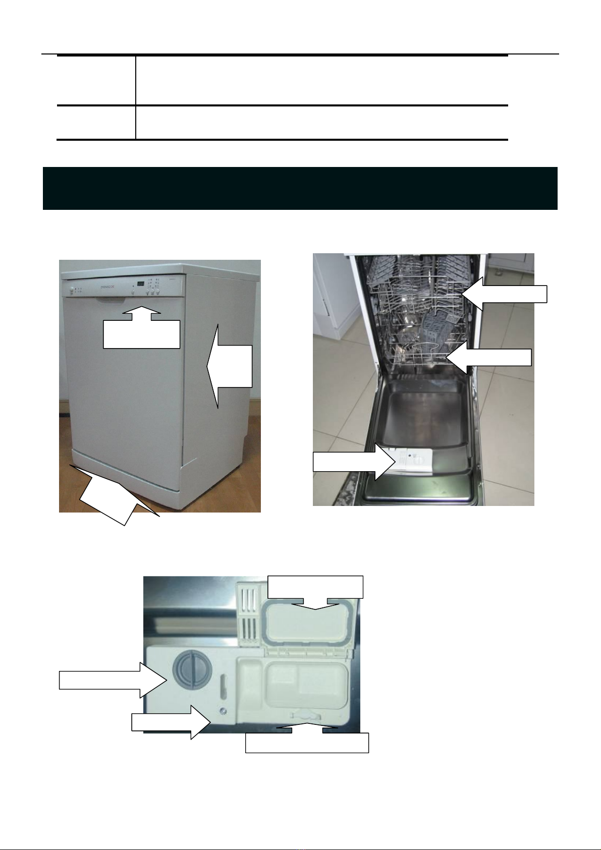
Dishwasher Components ................................................................... 4
Control Panel ................................................................................................. 4
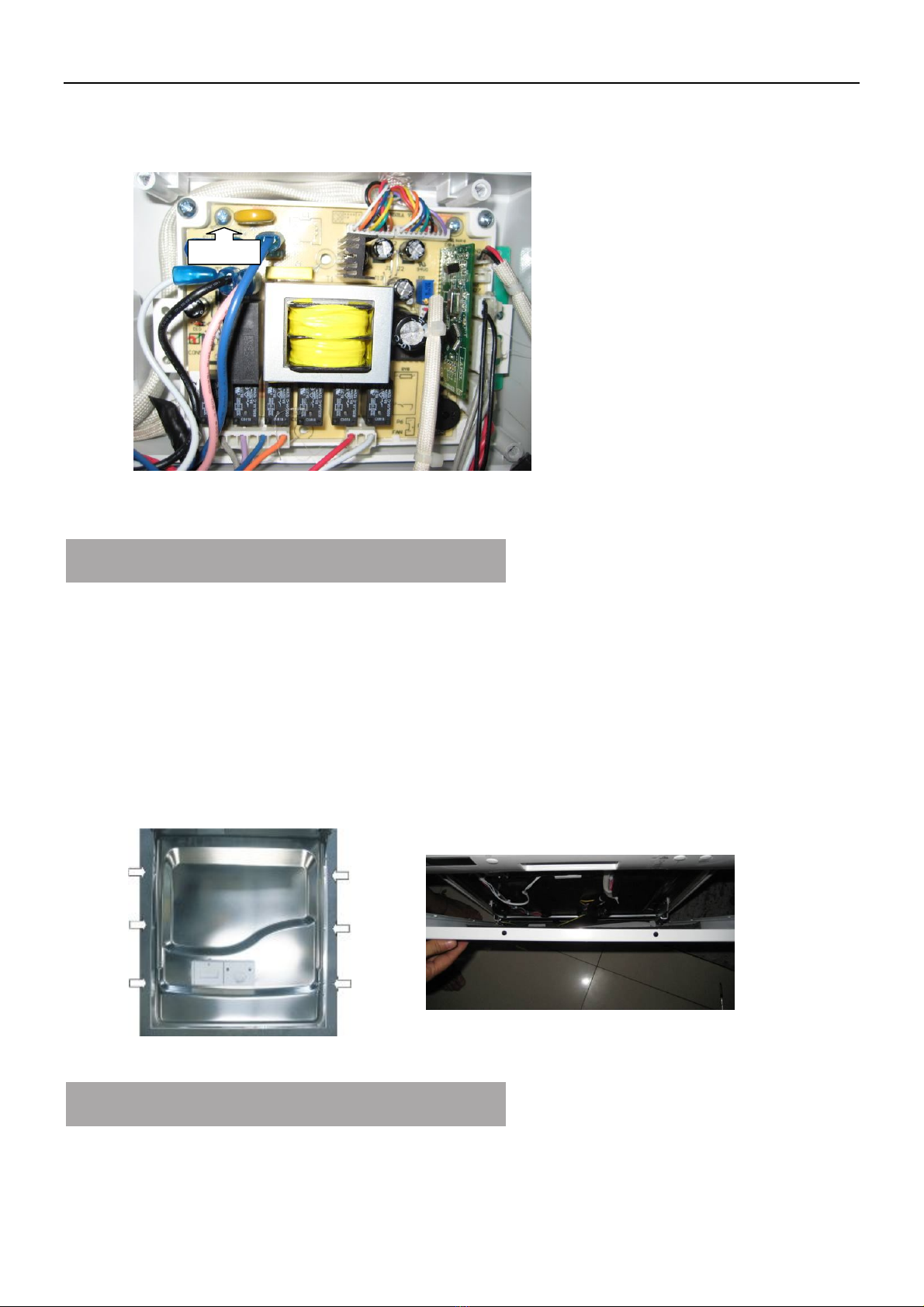
Electronic controller ....................................................................................... 5
Outer Door ..................................................................................................... 6
Dispenser ....................................................................................................... 6
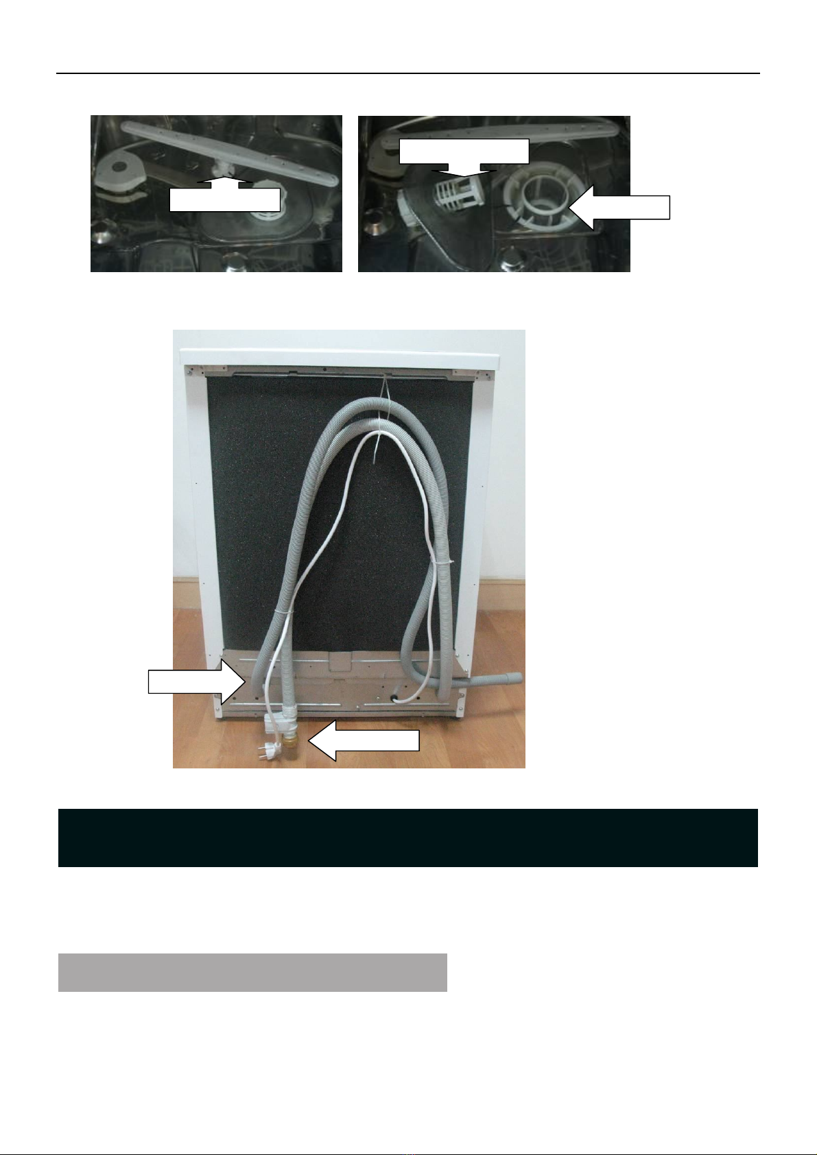
Outside panel ................................................................................................. 8
Door Assembly ............................................................................................ 10
Bottom Board............................................................................................... 12
Bottom Door Seal ........................................................................................ 13
Dishwasher Tub Seal.................................................................................... 14
Air breaker and Air inlet .............................................................................. 14
Overflow switch ........................................................................................... 15
Water softener .............................................................................................. 16
Water Valve ................................................................................................. 17
Pressure Switch ............................................................................................ 17
Motor Pump Assembly................................................................................. 20
Sump Assembly ........................................................................................... 21
Troubleshooting .............................................................................. 24
Warranty ......................................................................................... 28

2
It is a freestanding electrical dishwasher offers good washing performance to satisfy every washing
requirement. Its electronic control is easy and convenient to operate. The upper and lower racks can hold
up to 12 sets of dishes. The size (W: 0.6m, H: 0.85m, D: 0.58m) can easily fit in any corner of the kitchen,
and it’s recommended to locate at which the water hose connection is accessible.
Rating voltage:
220-240V, 50Hz
Heate
r
elements
:
1800W (
-
10%, +5 %
)
(230V)
Circuit
:
7.8
-
9.0A
W
ate
r
pressure
:
0.04MPa
-
1.0MPa
W
ate
r
temperature
:
Colde
r
water Sets
:
8
This guide just gives an example of all models for reference. About all detail of control
panel features, please see user manual of model you service.
1
Power Button and indicator light: turn on/off the power supply.
2
Salt and rinse aid warning lights: to show when the salt container
or dispenser need to be refilled.
3
Half washing button and indicator light: After selecting a wash
cycle, press this button to select the half washing. (It means that
the lower spray arm does not run, so you should load the upper
basket only).
4
Display Window: Display program remaining time, delay time,
fault codes, etc
5
Delayed Start Button: Press this button to set the delayed hours
for washing. You can delay the start of washing up to 24 hours.
One press on this button delays the start of washing by one hour.
6
Program button: Press the button to choose the desired program
Specification
Introduction
Control Panel Features
1
2
3
4
5
6
7
8

3
7
Start /Pause Button: Press this button to start or pause the
dishwasher, the process pilot lamp will com
e on when
starting.
8
Program indicator light.
Front View
Interior View (With Basket)
Dispenser Compartment View
Component Locator Views
Compartment Lid
Rinse Agent Cap
Sight Glass
Detergent Compartment
Dispenser
Lower basket
Upper basket
Control panel
Baseboard
Right
side
Panel

4
Interior View of Basin (With Basket Removed)
Back side view
Throughout this manual, features and appearance may vary from your model.
WARNING: Always turn off the electric power supply before servicing any
electrical component, making ohmmeter checks, or replacing any
parts.
Dishwasher Components
Control Panel
Lower Sprayer
Filter Assembly
Micro-filter
Drain Hose
Inlet Hose

5
Note: All voltage checks should be made with a voltmeter having a full scale
range of 250 volts or higher. After service is completed, be sure all
safet y grounding circuits are complete, all electrical connections are
secure, and all access panels are in place.
Removal and Installation
1. Disconnect the electrical supply from the dishwasher.
2. Open the dishwasher door.
3. Remove the 6 screws that connect the control panel cover to the
dishwasher door.
4. Close the dishwasher door.
5. Release the door latch and allow the control panel cover to hang
against the dishwasher door.
6. Unscrew the screws and disconnect the wire terminals for replace
PCBs, power switch and handle assembly.
The electronic controller allows the user to select the various cleaning
cycles of the dishwasher. All electrical elements in the dishwasher are
controlled by the electronic controller.
Removal and Installation
1. Electronic controller box local in the left side of dishwasher. So first
time we should take off the left side panel.(See outside panel)
2. Unscrew 2 screws that fix electronic controller box on left uprights,
and take off the electronic controller box by moving it along arrow.
Electronic controller

6
3. Unscrew 1screw and open the electronic controller box cover.
4. Unscrew 1screw and disconnect the wire terminals for replace PCBs.
5. Reverse the above procedure to install.
The outer door covers the door to the dishwasher and protects the detergent dispenser.
Removal and Installation
1. Disconnect power.
2. Open the dishwasher door.
3. Remove the 6 screws and the door panel from the door assembly. Do
not remove the 6 screws that hold the control panel cover to the door
assembly.
The dispenser automatically dispenses both the detergent and the rinse agent at the
appropriate times. The dispenser is activated twice during a wash cycle.
Dispenser
Outer Door
Screw

7
2
Cover
The first time the dispenser is activated (1),
the lever slides up the right-hand path of the
connecting rod.
This action moves the cover catch (2) and releases
the detergent cover.
When deactivated (3), the lever resets to rest under the
notch in the center of the connecting rod.
When activated for the second time in a cycle, the
lever lifts the connecting rod by the notch, lifting the rinse
dispenser plunger (4) and releasing the rinse agent. When
deactivated, the lever returns to its original starting
position.
The magnetic sensor (5) are connected to rinse aid
warning light at control panel by wires. When the indicator
lights up, it should add more rinse aid.
Removal and Replacement
1. Remove the out door insulation.
2. Disconnect the 4 terminals from the dispenser.
3. Remove the 3 screws and bottom mounting bracket.
1
4
5
3
5
4

8
4. Remove the 3 screws and top mounting bracket.
5. Remove the dispenser from door assembly.
Removal and Replacement
1. Disconnect power.
2. Remove the filter assembly, upper and lower basket.
3. Remove the outer door.
4. Remove the 2 screws that connect the top panel 2 cover to the
dishwasher.
5. Take off the top panel and remove the 2 screws.
6. Remove the 2 screws and baseboard from the dishwasher.
7. Remove the 2 screws connected to left and right side baseboard.
Outside panel
Dispenser
Top panel

9
8. Open the door and remove the 4 screws that connect side panels to
tub.
9. Remove the 4 screws in the front.
10. Remove the 8 screws at the back.
11. Remove the screws which are fixed to the left and right side panel.
12. Take off the left side panel.
13. Take off the upper rear crosspiece.
14. Take off the Back cover board.
15. Take off the right side panel.
Baseboard
Left side
baseboard
Right side
baseboard
Left side panel
Upper rear crosspiece
Right side panel

10
16. Take off the tub insulation over the dishwasher tub.
17. Reverse the above procedure to install.
Removal and Replacement
1. Disconnect power.
2. Remove the Outer Door.
3. Remove the 6 screws that connect the control panel cover to the
dishwasher door. (See electronic controller, step 3)
4. Close the dishwasher door.
5. Release the door latch and allow the control panel cover to hang
against the dishwasher door.
6. Disconnect the wire terminals from PCBs.
7. Disconnect the 2 terminal lugs from the Door Switch and Latch
Assembly.
8. Disconnect the 4 terminal lugs from the power switch.
9. Disconnect the 4 terminal lugs from the Dispenser switch.
10. Remove the bolt, nut, and ground wire from the door.
11. Pull the wire harness from the door.
Door Assembly

11
Note: There is a door hinge assembly on both the left and right sides of the
dishwasher. Both door hinge assemblies must be removed in order to
remove the door. The procedure to remove the right- side door hinge
assembly is outlined in steps 12 through 21. The left-side door hinge
assembly is identical.
12. Mark the position of the spring bolt key in the mounting bracket with
a felt-tip marker.
13. Pull the spring and spring bolt key from the mounting bracket.
14. Lift the bottom of the spring loop from the hinge arm stud.
15. Open the dishwasher door approximately 30 degrees.
16. Lift the bottom hinge arm up from the bottom hinge, far enough to expose the hook.
17. Close the dishwasher door.
Caution: The star washer is easily damaged during removal and should not be reused. Order
wire harness
Bolt, Nut, and
Ground Wire
Key
Bracket
Hook
Hinge

12
a new set of star washers.
18. Remove the star washer from the dishwasher door hinge.
19. Remove the hinge pin from the dish- washer door hinge.
20. Repeat steps 13 through 20 to remove the left side door hinge assembly.
21. Remove the dishwasher door from the dishwasher.
22. Reverse the above procedure to install.
Removal and replacement
1. Drain up the water in the dishwasher, and disconnect the power supply.
2. Lay down the dishwasher on its back.
3. Remove the 4 screws.
4. Pull out the bottom board.
5. Reverse the above procedure to install。
Bottom Board
Caution: The star washer
is easily damaged and
should not be reused.
Star washer
Pin

13
The bottom door seal prevents water leakage.
The seal is fitted in a pinched metal groove at the
bottom of the dish- washer door.
Removal and Replacement
1. Remove the Outer Door.
2. Remove the Door Assembly (see Door assembly).
3. Grab one end of the bottom door seal and peal it away from the pinched metal groove.
Warning: The pinched metal groove is sharp.
Wear Kevlar gloves when removing
or installing the door seal. Failure to
comply may result in personal injury.
4. Reverse the above procedure to install.
Note: When installing the door, seal make sure
it is seated properly in the pinched
metal groove. Run your finger over
the groove to make sure it is smooth
and even for a proper seal.
Bottom Door Seal

14
The dishwasher tub seal prevents water leakage. The seal is fitted in a seal channel that
lines the rim of the dishwasher tub.
Removal and Replacement
1. Open the dishwasher door.
2. Grab one end of the dishwasher tub seal and peal it away from the seal channel
3. Reverse the above procedure to install.
Note: When installing the tub seal, make sure it is seated properly in the seal channel. Run
your finger over the seal to make sure it is smooth and even for a proper seal. A
correctly installed gasket will have both ends of the gasket equidistant from the bottom
of the tub.
The air breaker is mounted on the left side of the tub. Its purpose is to provide a method
of supplying water for the wash and rinse cycles. The air gap prevents the siphoning of wash
water from flowing back into the water supply system, should the water pressure drop to less
than atmospheric pressure. The water in the air breaker is used to regenerate the water
softener.
The air inlet allows air into the tub to permit air flow for dish drying. Also the air can
flow out through the air breaker.
Removal and Replacement
1. Remove the outside panel.
2. Open the dishwasher door.
3. Loosen the clamp and disconnect the 3 air breaker hoses from
the air breaker.
4. Rotate the air breaker nut counter clock-wise and remove it.
5. Remove the air breaker.
Air breaker and Air inlet
Dishwasher Tub Seal
Seal Channel
Tub seal
Make sure the seal
is seated properly in
the seal channel.

15
Air inlet: it is installed to the right side of tub, whose assembly is similar to air breaker
assembly. But it should be that the clear plastic air tube is looped around that the air
inlet that protrudes into the dishwasher tub and mates with the air inlet nut.
6. Reverse the above procedure to install.
The overflow switch is designed to detect an overflow. When inlet water is too much or
some components are broken, it will do and E4 will be displayed in the display window in
control panel.
Removal and Replacement
1. Disconnect power.
2. Remove the bottom board (see bottom board).
3. Disconnect the 2 terminal lugs plugged on the overflow switch, then take off the float
support.
Overflow switch

16
The water softener is equipped with a special softener that uses a salt specifically
designed to eliminate lime and minerals from the water. If hard water is used in the
dishwasher, deposits will form on the dishes and utensils.
Removal and Replacement
1. Open the dishwasher door.
2. Remove the top panel, left side panel, right side panel,
baseboard and bottom board (see outside panel).
3. Remove the 4 terminal lugs connected to the water softener.
4. Loosen the clamp and disconnect the 3 hoses from the water softener.
5. Remove the lower basket and then unscrew and
remove the cap from the salt container.
Note: The clamping nut turns counter clock-wise and
may be difficult to remove. It may be necessary to
insert a screw driver or other tool between the
clamping nut tabs to enable you to apply sufficient
torque to break the factory seal.
6. Remove the clamping nut.
7. Remove the gasket (not shown) and the water
softener.
8. Reverse the above procedure to install.
Note: When remove softener and conjoint hoses, some
salt water will flow out. Make sure to wipe off the
water and operate a rinse procedure after
replacement.
Water softener
Tab
Clamping Nut

17
The water valve is electrical controlled and solenoid
operated. The flow of water is controlled by a
rubber flow washer capable of maintaining a flow
of 4±15% liters per minute with incoming water
pressure of 0.04~1MPa.The water valve is mounted
to the back hinge support of the dishwasher.
Removal and Replacement
1. Disconnect power.
2. Remove the top panel, left side panel, right side panel,
baseboard and bottom board (see outside panel).
3. Disconnect the 2 terminal lugs from the water fill
valve.
4. Push the valve from the bottom to take it off.
5. Remove the clamp and disconnect the tub fill hose
from the water valve.
6. Reverse the above procedure to install.
The pressure switch is located under the tub at the left,
front corner. A clear plastic tube, the pressure switch
hose, runs from the pressure switch, around the air inlet,
and to the sump. As the dishwasher basin fills with water,
the air pressure in the pressure switch hose increases.
When the pressure reaches the aim of value, the switch
will act and give a signal to electronic controller.
Pressure Switch
Water Valve
Water valve
Clamp
Terminal
s
Pressure switch
Water inlet
Presure
switch
hose
Left side of dishwasher
show the path of the
pressure switch hose.

18
Removal and Replacement
1. Disconnect power.
2. Remove the top panel, left side panel, right side panel, baseboard and bottom board
(see outside panel).
3. Remove the capillary tube from the pressure switch.
4. Turn the pressure switch clockwise to align the mounting tab vertically with the
mounting hole and remove the pressure switch from the dishwasher frame.
5. Label and disconnect the 2 terminal lugs from the pressure switch and remove it.
6. Reverse the above procedure to install.
Drain Pump Assembly
The drain pump assembly is located under the tub at the left rear corner. When operated with 230V
power, the pump will drain the water out of the dishwasher. A check valve flapper at the outlet of the
pump prevents the dirty water from flowing back to the dishwasher.
Removal & replacement
1、disconnect power
2、remove the bottom board。
3、label and disconnect the terminals of the pump
4、remove the two screws of the pump
Terminals

19
5、remove the pump by rotating the pump for 30°counterclockwise
6、Reverse the above procedure to install
Sump Assembly
The sump assembly consists of the filter assembly, micro-filter, sump clamping nut, sump gasket,
and sump. The filter assembly prevents large particles from reaching the micro-filter, and the
micro-filter prevents all small particles from flowing back to the cycle water. The filter assembly rests
above the sump and the micro-filter sits above the sump basin. The clamping nut fixes the sump to the
bottom of the dishwasher. The filter assembly, micro-filter, and sump clamping nut are assembled from
inside to outside. The gasket and sump are located under the tub bottom in front of the motor pump
assembly.
Removal & replacement
1、disconnect power
2、remove top panel, left/ right panel and bottom board
3、remove the pressure switch hose connected with the sump
Pressure
Switch Hose
Table of contents
Other Daewoo Dishwasher manuals