manuals.online logo
Brands
  1. Home
  2. •
  3. Brands
  4. •
  5. DAPAudio
  6. •
  7. Music Mixer
  8. •
  9. DAPAudio EM-7.2 Operation manual

DAPAudio EM-7.2 Operation manual

i
PRO'FssIONAL 5TEREO MIXER
E M-7 .2 / EM-5 1 / E f'A-7 .3
Please read before using this equipment
@. Pl.,g, ;E; I r[o[F
999199999991
x' qÆroloçDooo"Q.o | -
@" eô. Ë_Ë ë
T 1P T ,**,
0 | r0 J2 i+12 424+12 -124+12
UNR Lrfl Ê
@^@*
r.rt
"@ ofo d
E::'Ë::"'(.Ç
oo\=
lqôlô.rl
l@ @l@ @l
o@
-o
@@
o
@@
o
@
ô
@lô ôl
ool
ol@ @l
o@
@ ô'u
10 o l{
I .12-+12 .12 -+12 I
ooolooooooo I
X' q$oloç"ooo"e,o I
u @O Orr
o@Ë
::-@
tô ôt
lo"o I
@
"@ .f
E::."Ë
oo
tôô
lo'o
râ\
@O .,t"
o ot
ol6 ôlô ô
olo'o lo"o
o@ @
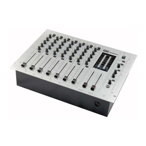
Front panel
1. POWER.LED
Lights up when the mixer's power is on.
2. MrC 1&2-SOCKET
You can connect microphones with XLR-plug and control the signals via the Mic Level-control.
3. ZONE.SELECT.BUTTONS
Route the channel signal to zone 1,2 & 3.
4. MIC LEVEL.CONTROL
With the MIC LEVEL-control, you can adjust the microphone volume.
5. MIC BASS.CONTROL
Used to increase or lower the LOWs of the input signal.
6. MIC MIDDLE.CONTROL
Used to increase or lower the MlDs of the input signal.
7. TREBLE.CONTROL
Used to increase or lower the Hls of the input signal.
8. MIC MUTE.BUTTON
This switch turns the corresponding signal of the Microphone channel on or mute
9. MIC PEAK LED
The Peak LED illuminates when Mic's signal is going into overload.
10. TALKOVER DB.CONTROL
Used to adjust the attenuation.
1 1. TALKOVER TIME.CONTROL
Used to adjust the response time.
12. TALKOVER.BUTTON
Press this button if you want to use your microphone. When the button is pressed, all signals but the microphone level
are attenuated by 15 dB.
13. CHANNEL.FADER
Used to adjust the input level of each channel.
14. CUE-BUTTON
Use the CUE-button in order to select the channel(s) to be monitored.
15. PHONO / LINE.SWITCH
Used to select the input to be sent to the individual channel.
16. CHANNEL PEAK LED
The Peak LED illuminates when channel's signal is going into overload.
1 7. ZON E.SELECT.BUTTONS
Route the channel signal to zone 1,2 & 3.
1 8. OUTPUT LEVEL.CONTROL
With the OUTPUT LEVEL-control, you can adjust the output level of the individual channel.
1 9. MASTER.BASS.CONTROL
Used to increase or lower the LOWs of the output signal.
20. MASTER MIDDLE.CONTROL
Used to increase or lower the MlDs of the output signal.
21. MASTER.TREBLE.CONTROL
Used to increase or lower the Hls of the output signal.
22. CHANNEL DISPLAY
The display shows the individual channel signal.
23. PHONE LEVEL.CONTROL
With the Level-control, you can adjust the phones volume without changing the output signal.
24. HEADPHONES.SOCKET
Use this socket to connect the headphones. Headphones from 8 Ohms to 600 Ohms can be used.
25. CUE MIXING.FADER
Connect your headphones to the HEADPHONES socket. With the CUE-buttons, you can select the desired channel.
When you set the CUE MIXINc-fader to PGM (CUE-buttons without function), you can cue the output signal of the
mixer. When you set the CUE MIXING-fader to the center position, you can cue both the channel-signal you selected
and the output-signal.
26. REC SELECT
For selecting the channel routed to the Master signal.
27. REC OUT
To connect your recording unit.
28. CUE MODE BUTTON (CUE SPL|T/CUE MIX BUTTON)
Cue Split-function (button pressed and): the Cue-signal is on the one side of the headphones and the output-signal on
the other side.
Cue Mix-function (button released): the adjustable mix of Cue-signal and output-signal is on both sides of the
headphones.
29. BOOTH.CONTROL
The mixer features a DJ BOOTH monitor system. Connect your monitor system with the BOOTH-sockets on the rear
panel.
30. LINE INPUT LEVEL.CONTROL
With the LEVEL-control, you can adjust the input level.
31. LINE INPUT.SOCKETS
Connect CD-player or Tape Deck with LINE input-socket.
32. REC NO MtC
Rear panel
1. POWER SWITCH
Press this button to start operating.
2. AC CONNECTION
Plug the power supply cable in here.
3. REC OUT
To connect your recording unit.
4. BALANCED MASTER OUT
Balanced output for the master signal.
5. MASTER OUT
Output sockets for connecting your power amplifier.
6. LINE INPUT.SOCKETS
Connect CD-players or Tape Decks connected with LINE input-sockets. Line level musical instruments with stereo
outputs such as Rhythm Machines or Samplers should also be connected with the LINE input-sockets.
7. PHONO INPUT.SOCKETS
Connect your turntable with the PHONO input-sockets.
8. REC WITH MIC/NO MIC
9. TRIM CONTROL
For pre-adjusting the input signal.
10. GND (Ground terminal)
Connect the ground lead of the turntable with this terminal. This helps to reduce humming and pop noises.
11. PHONO/LINE.SELECTOR
These switches select between the rear-panel Phono(RIAA) and Line inputs.
12. MtC 1&2€OCKET
You can connect microphones with XLR-plug and control the signals via the Mic Level-control.
13. Output Voltage Selector
The output voltage selector allows the unit to output signal either 0.75V or 1.5V
1 4. STEREO/MONO.SWITCH
Used to set the master output to mono or stereo. lf you connected a mono-signal via 1 RCA-socket, you can switch the
output signal to STEREO in order to have a stereo output signal.
15. BOOTH
Connect your monitor system with the BOOTH-sockets on the rear panel.
l0
TEGH N ICAL SPECI FICATIONS
ll
EM-7.2 EM-51 EM-7.3
Power supplv: 2x18VAC- 2x18VAC- 2x18VAC-
Power consumption: 18W 18W 25.2W
lnouts: 2 ohono. 10 line & 2 mic 2 phono, 10 line & 2 mic 2 phono, 10line & 2 mic
Outouts: 2Master, lBooth&1REC 3Master&1REC 3Master&1REC
Minimum input voltage:
Microphone: 1.5mV/ l Kohm 1.5mV/ l Kohm 1.5mV/ l Kohm
Phono: 2.6 mV / 51 Kohm 2.6 mV / 51 Kohm 2.6 mV / 51 Kohm
Line: 150 mV / 50 Kohm 150 mV i 50 Kohm 150 mV / 50 Kohm
Aux ln: 150 mV RMS 150 mV RMS 150 mV RMS
Outout voltaqe:
Master 10,75V11,5 V RMS. XLR 0,75V11,5 V RMS, XLR 0.75V11,5 V RMS, XLR
Master 2: 0,75V11,5 V RMS, XLR 0,75V11,5 V RMS, XLR 0,75V11,5 V RMS, XLR
Master 3: O,75V11,5 V RMS, XLR 0,75V11,5 V RMS, XLR
Booth: 0,75V11,5 V RMS
Record: 0,75 V RMS 0,75 V RMS 0,75 V RMS
Headphones: 8 Ohms or more 8 Ohms or more I Ohms or more
Outputs: 2 Master-Out, 1 Rec-Out & 1
Booth-Out via RCA 3Master-Out&1Rec-Out 3Master-Out&1Rec-Out
Master 1 Out: Unbalanced RCA pin jack &
balanced XLR-connectors Unbalanced RCA pin jack &
balanced XLR-connectors
Master 2 Out: Unbalanced RCA pin jack &
balanced XLR-connectors Unbalanced RCA pin jack &
balanced XLR-connectors
Master 3 Out: Unbalanced RCA pin jack &
balanced XLR-connectors Unbalanced RCA pin jack &
balanced XLR-connectors
Booth Out: Unbalanced RCA pin iack
Freouencv ranoe: 20 -20 000 Hz 20 -20 000 Hz 20 -20KHz
Distortion: <0,03 %<0,03 %<0,03 %
S/N-ratio: >65 dB >65 dB >65 dB
Talkover-attenuation :-15 dB -15 dB -15 dB
Tone control:
Treble: 10 KHz -12 dBl +12 dB 10 KHz -12 dBl +12 dB 10 KHz -12 dBl +12 dB
Middle: 1 KHz -12 dBl +12 dB 1 KHz -12 dBl +12 dB 1 KHz -12 dBl +12 dB
Bass: 100 Hz _12 dBt +12 dB '100 Hz -12 dBl +12 dB 100 Hz -12 dBl +12 dB
Dimensions(WxDxH): 483 x 135 x 90 mrn 483 x 135 x 90 mm 483 x 135 x 90 mm
Weiqhl 2.9Kq 2.9Kq 3.2Ks
Weiqht with power supply: 3.5Ks 3.5Kq 3.8Kg
EC(
GAUTION:
The apparatus shall not be exposed to dripping or splashing and that no objects filled with liquids, such as vases, shall
be placed on the apparatus. 54tN499.042709
t2

This manual suits for next models

2

Other DAPAudio Music Mixer manuals

DAPAudio Gig 8 User manual

DAPAudio

DAPAudio Gig 8 User manual

DAPAudio Sessionmix 6 User manual

DAPAudio

DAPAudio Sessionmix 6 User manual

DAPAudio GIG-1000CFX User manual

DAPAudio

DAPAudio GIG-1000CFX User manual

DAPAudio IMIX 5.3 User manual

DAPAudio

DAPAudio IMIX 5.3 User manual

DAPAudio LIVE 16 User manual

DAPAudio

DAPAudio LIVE 16 User manual

DAPAudio Gig 14 User manual

DAPAudio

DAPAudio Gig 14 User manual

DAPAudio Core Scratch User manual

DAPAudio

DAPAudio Core Scratch User manual

DAPAudio IM-53 User manual

DAPAudio

DAPAudio IM-53 User manual

DAPAudio Sessionmix 8 User manual

DAPAudio

DAPAudio Sessionmix 8 User manual

DAPAudio GIG-124C User manual

DAPAudio

DAPAudio GIG-124C User manual

DAPAudio GIG-12 User manual

DAPAudio

DAPAudio GIG-12 User manual

DAPAudio IMIX-7.3 User manual

DAPAudio

DAPAudio IMIX-7.3 User manual

DAPAudio Core Club User manual

DAPAudio

DAPAudio Core Club User manual

DAPAudio MMIX-4 User manual

DAPAudio

DAPAudio MMIX-4 User manual

DAPAudio PMM-401 User manual

DAPAudio

DAPAudio PMM-401 User manual

DAPAudio Platinum User manual

DAPAudio

DAPAudio Platinum User manual

DAPAudio Core Beat V2 User manual

DAPAudio

DAPAudio Core Beat V2 User manual

DAPAudio DS-CDJ-250 MKII User manual

DAPAudio

DAPAudio DS-CDJ-250 MKII User manual

DAPAudio Sessionmix 12 DSP User manual

DAPAudio

DAPAudio Sessionmix 12 DSP User manual

DAPAudio AMM-401 User manual

DAPAudio

DAPAudio AMM-401 User manual

DAPAudio Core Beat User manual

DAPAudio

DAPAudio Core Beat User manual
DAPAudio IMIX-7.1 User manual

DAPAudio

DAPAudio IMIX-7.1 User manual

DAPAudio IMIX-7.2 USB User manual

DAPAudio

DAPAudio IMIX-7.2 USB User manual

DAPAudio Oxygen User manual

DAPAudio

DAPAudio Oxygen User manual
Popular Music Mixer manuals by other brands

Yamaha PM3500 operating manual

Yamaha

Yamaha PM3500 operating manual

Louroe Electronics RN-2 Installation and operating instructions

Louroe Electronics

Louroe Electronics RN-2 Installation and operating instructions

Korg 168RC Service manual

Korg

Korg 168RC Service manual

Tapco Blend 6 owner's manual

Tapco

Tapco Blend 6 owner's manual

Peavey XR 560 operating guide

Peavey

Peavey XR 560 operating guide

Phonic AM55 user manual

Phonic

Phonic AM55 user manual

Crown COMMERCIAL AUDIO 160MA Operation manual

Crown

Crown COMMERCIAL AUDIO 160MA Operation manual

Eela Audio D3 Quick start manual

Eela Audio

Eela Audio D3 Quick start manual

YORKVILLE M1610 parts list

YORKVILLE

YORKVILLE M1610 parts list

Yamaha 01V96 VCM specification

Yamaha

Yamaha 01V96 VCM specification

Alesis MultiMix8FireWire Reference manual

Alesis

Alesis MultiMix8FireWire Reference manual

Stageline MMX-3USB instruction manual

Stageline

Stageline MMX-3USB instruction manual

Phonic POWERPOD 410 user manual

Phonic

Phonic POWERPOD 410 user manual

PRESONUS StudioLive RM32AI owner's manual

PRESONUS

PRESONUS StudioLive RM32AI owner's manual

Yamaha MG10 Technical specifications

Yamaha

Yamaha MG10 Technical specifications

Studiomaster DJX 925 manual

Studiomaster

Studiomaster DJX 925 manual

MAM RS3 Operation manual

MAM

MAM RS3 Operation manual

YORKVILLE PowerMAX PM16 Service manual

YORKVILLE

YORKVILLE PowerMAX PM16 Service manual

manuals.online logo
manuals.online logoBrands
  • About & Mission
  • Contact us
  • Privacy Policy
  • Terms and Conditions

Copyright 2025 Manuals.Online. All Rights Reserved.