Datex-Ohmeda Aestiva 7900 SmartVent User manual

7900 Ventilator Supplemental to the Datex-Ohmeda Excel SE
and Modulus SE Anesthesia Machine Service Manual.
Ventilator Software Revision 2.X

1
503-0151-000
3/27/97

1
503-0151-000
3/27/97
Ohmeda 7900 Anesthesia Ventilator
Supplement to Excel SE and Modulus SE Anesthesia Machine Service Manual
Ventilator Software Revision 2.X

1
503-0151-000
3/27/97

Table of Contents
1503-0151-000 3/27/97 i
1/ Introduction
1.1. What this manual includes . . . . . . . . . . . . . . . . . . . . . . . . . . . . . . . . . . . . . . . . . .1-2
1.2. Symbols . . . . . . . . . . . . . . . . . . . . . . . . . . . . . . . . . . . . . . . . . . . . . . . . . . . . . . .1-3
1.3. Standard Service Procedures . . . . . . . . . . . . . . . . . . . . . . . . . . . . . . . . . . . . . . .1-4
Operation and Service Manuals . . . . . . . . . . . . . . . . . . . . . . . . . . . . . . . .1-4
Ventilator Tests . . . . . . . . . . . . . . . . . . . . . . . . . . . . . . . . . . . . . . . . . . . . .1-4
1.4. 7900 Ventilator Configuration . . . . . . . . . . . . . . . . . . . . . . . . . . . . . . . . . . . . . . .1-5
Software Versions . . . . . . . . . . . . . . . . . . . . . . . . . . . . . . . . . . . . . . . . . . .1-5
2/ Theory of Operation
2.1. General . . . . . . . . . . . . . . . . . . . . . . . . . . . . . . . . . . . . . . . . . . . . . . . . . . . . . . .2-1
7900 Ventilator Features . . . . . . . . . . . . . . . . . . . . . . . . . . . . . . . . . . . . . .2-2
Safety Features . . . . . . . . . . . . . . . . . . . . . . . . . . . . . . . . . . . . . . . . . . . . .2-3
2.2. Mechanical . . . . . . . . . . . . . . . . . . . . . . . . . . . . . . . . . . . . . . . . . . . . . . . . . . . . . .2-3
2.3. Electrical . . . . . . . . . . . . . . . . . . . . . . . . . . . . . . . . . . . . . . . . . . . . . . . . . . . . . . .2-9
Power Supply Assembly . . . . . . . . . . . . . . . . . . . . . . . . . . . . . . . . . . . . .2-10
Power Supply . . . . . . . . . . . . . . . . . . . . . . . . . . . . . . . . . . . . . . .2-10
Synchrononus step-down regulator . . . . . . . . . . . . . . . . . . . . . . .2-13
External Interface . . . . . . . . . . . . . . . . . . . . . . . . . . . . . . . . . . . . . . . . . .2-14
Communication Interface (RS232C) . . . . . . . . . . . . . . . . . . . . . . . . . . . .2-14
External Interface Connector . . . . . . . . . . . . . . . . . . . . . . . . . . . . . . . . . .2-14
Sealed Lead Acid Battery . . . . . . . . . . . . . . . . . . . . . . . . . . . . . . . . . . . .2-14
Input . . . . . . . . . . . . . . . . . . . . . . . . . . . . . . . . . . . . . . . . . . . . . . . . . . . .2-14
Output . . . . . . . . . . . . . . . . . . . . . . . . . . . . . . . . . . . . . . . . . . . . . . . . . . .2-14
Microcontroller Assembly . . . . . . . . . . . . . . . . . . . . . . . . . . . . . . . . . . . .2-15
Functional Specifications . . . . . . . . . . . . . . . . . . . . . . . . . . . . . . .2-15
Program Memory . . . . . . . . . . . . . . . . . . . . . . . . . . . . . . . . . . . . . . . . . . .2-17
Flash EPROM . . . . . . . . . . . . . . . . . . . . . . . . . . . . . . . . . . . . . . .2-17
System RAM . . . . . . . . . . . . . . . . . . . . . . . . . . . . . . . . . . . . . . . .2-17
Non-Volatile Memory . . . . . . . . . . . . . . . . . . . . . . . . . . . . . . . . . .2-17
Safety Relevant Computing . . . . . . . . . . . . . . . . . . . . . . . . . . . . . . . . . . .2-17
Watchdog Systems . . . . . . . . . . . . . . . . . . . . . . . . . . . . . . . . . . . . . . . . .2-18
68040 Software Watchdog Timer . . . . . . . . . . . . . . . . . . . . . . . .2-18
Operating Mode Watchdog . . . . . . . . . . . . . . . . . . . . . . . . . . . . .2-18
Error Response Sequence . . . . . . . . . . . . . . . . . . . . . . . . . . . . .2-18
DATA Acquisition . . . . . . . . . . . . . . . . . . . . . . . . . . . . . . . . . . . . . . . . . .2-19
Analog to Digital Converter System . . . . . . . . . . . . . . . . . . . . . . .2-19
Multiplexer and Buffer Amplifier . . . . . . . . . . . . . . . . . . . . . . . . . .2-20
A/D Converter . . . . . . . . . . . . . . . . . . . . . . . . . . . . . . . . . . . . . . .2-20
Voltage Reference . . . . . . . . . . . . . . . . . . . . . . . . . . . . . . . . . . . .2-21
Flow Valve Control . . . . . . . . . . . . . . . . . . . . . . . . . . . . . . . . . . . .2-21
Gas Inlet Valve Drive Circuit . . . . . . . . . . . . . . . . . . . . . . . . . . . . . . . . . .2-22
Front Panel Display Interface . . . . . . . . . . . . . . . . . . . . . . . . . . . . . . . . .2-22
EL Display Controller . . . . . . . . . . . . . . . . . . . . . . . . . . . . . . . . . .2-22
Video Display Memory . . . . . . . . . . . . . . . . . . . . . . . . . . . . . . . . .2-22
Membrane Switch Inputs . . . . . . . . . . . . . . . . . . . . . . . . . . . . . . .2-22
LED Driver Outputs . . . . . . . . . . . . . . . . . . . . . . . . . . . . . . . . . . .2-22
Rotary Encoder Input . . . . . . . . . . . . . . . . . . . . . . . . . . . . . . . . . .2-22
Mechanical Ventilation Switch . . . . . . . . . . . . . . . . . . . . . . . . . . .2-23
Audio Alarm . . . . . . . . . . . . . . . . . . . . . . . . . . . . . . . . . . . . . . . . . . . . . . .2-23
Manifold Pressures . . . . . . . . . . . . . . . . . . . . . . . . . . . . . . . . . . . . . . . . .2-23
Front Panel Assembly . . . . . . . . . . . . . . . . . . . . . . . . . . . . . . . . . . . . . . .2-23
Sensor Interface Board (SIB) . . . . . . . . . . . . . . . . . . . . . . . . . . . . . . . . .2-24

Table of Contents
ii 1503-0151-000 3/27/97
Inspiratory and Expiratory Flow Measurement . . . . . . . . . . . . . .2-24
Patient Airway Pressure Measurement . . . . . . . . . . . . . . . . . . . .2-24
O2 Concentration Measurement . . . . . . . . . . . . . . . . . . . . . . . . .2-25
Switch Connections . . . . . . . . . . . . . . . . . . . . . . . . . . . . . . . . . . .2-25
3/ Post Service Checkout
Test the Ventilator. . . . . . . . . . . . . . . . . . . . . . . . . . . . . . . . . . . . . . . . . . . . . . . . . . . .3-1
Test the Anesthesia System. . . . . . . . . . . . . . . . . . . . . . . . . . . . . . . . . . . . . . . . . . . .3-1
Test all Options and Accessories. . . . . . . . . . . . . . . . . . . . . . . . . . . . . . . . . . . . . . . . .3-1
4/ Tests and Troubleshooting
4.1. Overview . . . . . . . . . . . . . . . . . . . . . . . . . . . . . . . . . . . . . . . . . . . . . . . . . . . . . . .4-1
Testing Requirements . . . . . . . . . . . . . . . . . . . . . . . . . . . . . . . . . . . . . . . .4-1
4.2. Service Mode Menu . . . . . . . . . . . . . . . . . . . . . . . . . . . . . . . . . . . . . . . . . . . . . . .4-3
4.3. Diagnostic Tests . . . . . . . . . . . . . . . . . . . . . . . . . . . . . . . . . . . . . . . . . . . . . . . . . 4-4
Test CPU . . . . . . . . . . . . . . . . . . . . . . . . . . . . . . . . . . . . . . . . . . . . . . . . . .4-4
Test External RAM . . . . . . . . . . . . . . . . . . . . . . . . . . . . . . . . . . . . . . . . . .4-5
Test Display RAM . . . . . . . . . . . . . . . . . . . . . . . . . . . . . . . . . . . . . . . . . . .4-5
Test Flash ROM . . . . . . . . . . . . . . . . . . . . . . . . . . . . . . . . . . . . . . . . . . . .4-6
Test EEPROM . . . . . . . . . . . . . . . . . . . . . . . . . . . . . . . . . . . . . . . . . . . . . .4-7
Test Panel Switches . . . . . . . . . . . . . . . . . . . . . . . . . . . . . . . . . . . . . . . . .4-8
Test Serial Ports . . . . . . . . . . . . . . . . . . . . . . . . . . . . . . . . . . . . . . . . . . .4-10
Test Flow Valve . . . . . . . . . . . . . . . . . . . . . . . . . . . . . . . . . . . . . . . . . . . .4-11
Test Gas Inlet Valve (GIV) . . . . . . . . . . . . . . . . . . . . . . . . . . . . . . . . . . .4-12
Gas Inlet Valve FAIL Instructions: . . . . . . . . . . . . . . . . . . . . . . . 4-12
Test Pressure Limit Switch . . . . . . . . . . . . . . . . . . . . . . . . . . . . . . . . . . .4-13
Pressure Limit Switch FAIL Instructions: . . . . . . . . . . . . . . . . . . .4-14
4.4. Diagnostic tools. . . . . . . . . . . . . . . . . . . . . . . . . . . . . . . . . . . . . . . . . . . . . . . . . .4-15
Display A/D channels . . . . . . . . . . . . . . . . . . . . . . . . . . . . . . . . . . . . . . .4-15
Display I/O signals . . . . . . . . . . . . . . . . . . . . . . . . . . . . . . . . . . . . . . . . . .4-16
Display Battery Charge Status . . . . . . . . . . . . . . . . . . . . . . . . . . . . . . . .4-17
System Error Log . . . . . . . . . . . . . . . . . . . . . . . . . . . . . . . . . . . . . . . . . .4-18
System Error Log Codes . . . . . . . . . . . . . . . . . . . . . . . . . . . . . . . . . . . . .4-19
Verify Flow . . . . . . . . . . . . . . . . . . . . . . . . . . . . . . . . . . . . . . . . . . . . . . . .4-23
4.5. Calibrations . . . . . . . . . . . . . . . . . . . . . . . . . . . . . . . . . . . . . . . . . . . . . . . . . . . .4-24
Calibrate O2 Sensor . . . . . . . . . . . . . . . . . . . . . . . . . . . . . . . . . . . . . . . .4-24
Calibrate Flow Sensors . . . . . . . . . . . . . . . . . . . . . . . . . . . . . . . . . . . . . .4-25
Calibrate Pressure Sensitivity . . . . . . . . . . . . . . . . . . . . . . . . . . . . . . . . .4-28
Calibrate Flow Valve . . . . . . . . . . . . . . . . . . . . . . . . . . . . . . . . . . . . . . . .4-30
Calibrate Bleed Resistor . . . . . . . . . . . . . . . . . . . . . . . . . . . . . . . . . . . . .4-31
Sensor(s) Cal Due . . . . . . . . . . . . . . . . . . . . . . . . . . . . . . . . . . . . . . . . . .4-34
4.6. User Settings . . . . . . . . . . . . . . . . . . . . . . . . . . . . . . . . . . . . . . . . . . . . . . . . . . .4-35
Select Altitude . . . . . . . . . . . . . . . . . . . . . . . . . . . . . . . . . . . . . . . . . . . . .4-35
Select Drive Gas . . . . . . . . . . . . . . . . . . . . . . . . . . . . . . . . . . . . . . . . . . .4-35
Adjust Brightness . . . . . . . . . . . . . . . . . . . . . . . . . . . . . . . . . . . . . . . . . .4-36
Select Heliox Mode . . . . . . . . . . . . . . . . . . . . . . . . . . . . . . . . . . . . . . . . .4-36
Exit Service Mode . . . . . . . . . . . . . . . . . . . . . . . . . . . . . . . . . . . . . . . . . .4-37
4.7. Troubleshooting Guides . . . . . . . . . . . . . . . . . . . . . . . . . . . . . . . . . . . . . . . . . . .4-38
Troubleshooting Mechanical/Electrical . . . . . . . . . . . . . . . . . . . . . . . . . .4-38
Troubleshooting by Alarm Messages . . . . . . . . . . . . . . . . . . . . . . . . . . .4-40

Table of Contents
1503-0151-000 3/27/97 iii
5/ Maintenance
5.1. Maintenance Schedule . . . . . . . . . . . . . . . . . . . . . . . . . . . . . . . . . . . . . . . . . . . .5-1
Maintenance . . . . . . . . . . . . . . . . . . . . . . . . . . . . . . . . . . . . . . . . . . . . . . .5-1
Yearly Maintenance Checks . . . . . . . . . . . . . . . . . . . . . . . . . . . . . . . . . . .5-1
Two Year Maintenance . . . . . . . . . . . . . . . . . . . . . . . . . . . . . . . . . . . . . . .5-1
5.2. Maintenance Procedures . . . . . . . . . . . . . . . . . . . . . . . . . . . . . . . . . . . . . . . . . . .5-2
Exhalation Valve Maintenance . . . . . . . . . . . . . . . . . . . . . . . . . . . . . . . . .5-2
Supply Gas Inlet Filter . . . . . . . . . . . . . . . . . . . . . . . . . . . . . . . . . . . . . . . .5-2
Free Breathing Valve Maintenance . . . . . . . . . . . . . . . . . . . . . . . . . . . . . .5-3
6/ Repair Procdures
6.1.General . . . . . . . . . . . . . . . . . . . . . . . . . . . . . . . . . . . . . . . . . . . . . . . . . . . . . . .6-1
Assemblies -- tools for removal and installation . . . . . . . . . . . . . . . . . . . .6-1
6.2. Removing the 7900 ventilator from the Ohmeda Excel/Modulus SE Gas Machine 6-2
Removing the 7900 ventilator from the integrated machine . . . . . . . . . . .6-2
Removing the 7900 ventilator from the non-integrated machine . . . . . . . .6-4
6.3. Setting up the Service Shelf . . . . . . . . . . . . . . . . . . . . . . . . . . . . . . . . . . . . . . . . .6-7
6.4. Removing the top cover . . . . . . . . . . . . . . . . . . . . . . . . . . . . . . . . . . . . . . . . . . . .6-9
6.5. Printed circuit board and power module removal . . . . . . . . . . . . . . . . . . . . . . . .6-11
Removing the Power Supply circuit board and the Microcontroller circuit
board . . . . . . . . . . . . . . . . . . . . . . . . . . . . . . . . . . . . . . . . . . . . . . . . . . . .6-11
Removing Power Supply circuit board . . . . . . . . . . . . . . . . . . . . . . . . . .6-11
Removing Microcontroller circuit board . . . . . . . . . . . . . . . . . . . . . . . . . .6-14
Firmware Replacement Procedure . . . . . . . . . . . . . . . . . . . . . . . . . . . . .6-16
Software Upload Procedure . . . . . . . . . . . . . . . . . . . . . . . . . . . . .6-17
Ohmeda Software Upgrade Tool . . . . . . . . . . . . . . . . . . . . . . . . .6-17
To Install Ohmeda Software Upgrade Tool . . . . . . . . . . . . . . . . .6-17
To Install 7900 Software Field Upgrade. . . . . . . . . . . . . . . . . . . .6-18
To Perform Software Upgrade . . . . . . . . . . . . . . . . . . . . . . . . . . .6-18
Microcontroller board . . . . . . . . . . . . . . . . . . . . . . . . . . . . . . . . . . . . . . . .6-18
Removing the front panel . . . . . . . . . . . . . . . . . . . . . . . . . . . . . . . . . . . .6-19
Replacing the display board . . . . . . . . . . . . . . . . . . . . . . . . . . . . . . . . . .6-19
Replacing the encoder switch . . . . . . . . . . . . . . . . . . . . . . . . . . . . . . . . .6-21
Removing the battery . . . . . . . . . . . . . . . . . . . . . . . . . . . . . . . . . . . . . . .6-22
Testing After Maintenance . . . . . . . . . . . . . . . . . . . . . . . . . . . . . . . . . . .6-23
6.6. Replacing the isolation transformer . . . . . . . . . . . . . . . . . . . . . . . . . . . . . . . . . .6-24
Removing the power module . . . . . . . . . . . . . . . . . . . . . . . . . . . . . . . . . 6-24
Prepare power module for removal . . . . . . . . . . . . . . . . . . . . . . . . . . . . .6-25
Isolation transformer removal . . . . . . . . . . . . . . . . . . . . . . . . . . . . . . . . .6-26
Alarm speaker removal . . . . . . . . . . . . . . . . . . . . . . . . . . . . . . . . . . . . . .6-27
Power cord inlet removal . . . . . . . . . . . . . . . . . . . . . . . . . . . . . . . . . . . . .6-28
6.7. Pneumatic subassembly removal . . . . . . . . . . . . . . . . . . . . . . . . . . . . . . . . . . .6-29
Removing the non-relieving regulator . . . . . . . . . . . . . . . . . . . . . . . . . . .6-29
Removing the flow control valve . . . . . . . . . . . . . . . . . . . . . . . . . . . . . . .6-30
Removing the solenoid and gas inlet valve assembly . . . . . . . . . . . . . . .6-32
Removing the GIV assembly . . . . . . . . . . . . . . . . . . . . . . . . . . . .6-32
Removing the solenoid switch . . . . . . . . . . . . . . . . . . . . . . . . . . .6-32
6.8. Gas Inlet Valve Repair . . . . . . . . . . . . . . . . . . . . . . . . . . . . . . . . . . . . . . . . . . . .6-33
Removing the Mechanical Over-pressure Bleed Off valve (MOBO)
assembly . . . . . . . . . . . . . . . . . . . . . . . . . . . . . . . . . . . . . . . . . . . . . . . . .6-35
MOBO removal (See figure 6-30) . . . . . . . . . . . . . . . . . . . . . . . . . . . . . .6-36
MOBO installation and low pressure operation check . . . . . . . . . . . . . .6-36

Table of Contents
iv 1503-0151-000 3/27/97
Mechanically cycle MOBO weights (See figure 6-30) . . . . . . . . . . . . . . .6-38
Removing the Drive gas check valve assembly . . . . . . . . . . . . . . . . . . .6-39
Removing the pressure sensing switch assembly . . . . . . . . . . . . . . . . . .6-40
6.9. SIB Removal from Excel/Modulus SE . . . . . . . . . . . . . . . . . . . . . . . . . . . . . . . .6-41
SIB (Sensor Interface Board) Assembly Removal . . . . . . . . . . . . . . . . . .6-42
Replacement Calibration Instructions (SIB) . . . . . . . . . . . . . . . . . . . . . .6-43
6.10. Patient Interface Harness Removal from Excel SE . . . . . . . . . . . . . . . . . . . . .6-43
6.11. Patient Interface Panel/Harness Assembly Removal From Modulus SE . . . . .6-44
6.12. SIB/Machine INterface Harness Removal . . . . . . . . . . . . . . . . . . . . . . . . . . . .6-46
6.13. Test unit after repair as follows . . . . . . . . . . . . . . . . . . . . . . . . . . . . . . . . . . . .6-46
7/ Illustrated Parts List
7.1. General . . . . . . . . . . . . . . . . . . . . . . . . . . . . . . . . . . . . . . . . . . . . . . . . . . . . . . .7-1
Special Instructions . . . . . . . . . . . . . . . . . . . . . . . . . . . . . . . . . . . . . . . . . .7-1
Stock Numbers for Replacement Parts . . . . . . . . . . . . . . . . . . . . . . . . . . .7-1
7.2. 7900 SERVICE KITS: . . . . . . . . . . . . . . . . . . . . . . . . . . . . . . . . . . . . . . . . . . . . .7-1
SIB Harnesses . . . . . . . . . . . . . . . . . . . . . . . . . . . . . . . . . . . . . . . . . . . .7-16
8/ Schematics
9/ Accessories, Miscellaneous Parts
7900 Accessory and Bellows Mounting Kits: . . . . . . . . . . . . . . . . . . . . . . . . . . . . . . .9-1
O&M Manuals: . . . . . . . . . . . . . . . . . . . . . . . . . . . . . . . . . . . . . . . . . . . . . . . . . . . . . .9-2

List of Illustrations
1503-0151-000 3/27/97 v
List of Illustrations
Section 2
Figure 2-1 7900 Ventilator - Excel SE and Modulus SE Anesthesia System
Interface. . . . . . . . . . . . . . . . . . . . . . . . . . . . . . . . . . . . . . . . . . . . . . . .2-1
Figure 2-2 7900 Ventilator Operational Block Diagram . . . . . . . . . . . . . . . . . . . .2-2
Figure 2-3 Supply gas inlet, filtered . . . . . . . . . . . . . . . . . . . . . . . . . . . . . . . . . . .2-3
Figure 2-4 Gas Inlet Valve . . . . . . . . . . . . . . . . . . . . . . . . . . . . . . . . . . . . . . . . . .2-3
Figure 2-5 Non-Relieving Pressure Regulator . . . . . . . . . . . . . . . . . . . . . . . . . . .2-4
Figure 2-6 Flow Control Valve . . . . . . . . . . . . . . . . . . . . . . . . . . . . . . . . . . . . . . .2-4
Figure 2-7 Exhalation Manifold . . . . . . . . . . . . . . . . . . . . . . . . . . . . . . . . . . . . . . .2-5
Figure 2-8 Drive Gas Check Valve . . . . . . . . . . . . . . . . . . . . . . . . . . . . . . . . . . . .2-6
Figure 2-9 MOBO (Mechanical Over pressure Bleed Off) . . . . . . . . . . . . . . . . . .2-7
Figure 2-10 Bleed Resistor, Pressure Switch and Free Breathing Valve . . . . . . . .2-8
Figure 2-11 Electronic functional block diagram . . . . . . . . . . . . . . . . . . . . . . . . . . .2-9
Section 4
Figure 4-1 Service mode main menu . . . . . . . . . . . . . . . . . . . . . . . . . . . . . . . . . .4-3
Displays Test CPU . . . . . . . . . . . . . . . . . . . . . . . . . . . . . . . . . . . . . . . . . . . . . . 4-4
Test External RAM . . . . . . . . . . . . . . . . . . . . . . . . . . . . . . . . . . . . . . .4-5
Test Display RAM . . . . . . . . . . . . . . . . . . . . . . . . . . . . . . . . . . . . . . . .4-5
Test Flash ROM . . . . . . . . . . . . . . . . . . . . . . . . . . . . . . . . . . . . . . . . .4-6
Test EEPROM . . . . . . . . . . . . . . . . . . . . . . . . . . . . . . . . . . . . . . . . . . .4-7
Test Front Panel . . . . . . . . . . . . . . . . . . . . . . . . . . . . . . . . . . . . . . . . .4-8
Test Serial Ports . . . . . . . . . . . . . . . . . . . . . . . . . . . . . . . . . . . . . . . .4-10
Test Flow Valve . . . . . . . . . . . . . . . . . . . . . . . . . . . . . . . . . . . . . . . .4-11
Test Gas Inlet Valve . . . . . . . . . . . . . . . . . . . . . . . . . . . . . . . . . . . . .4-12
Test Pressure Limit Switch . . . . . . . . . . . . . . . . . . . . . . . . . . . . . . . .4-13
Display A/D Channels . . . . . . . . . . . . . . . . . . . . . . . . . . . . . . . . . . . 4-15
Discrete I/O Signals . . . . . . . . . . . . . . . . . . . . . . . . . . . . . . . . . . . . . .4-16
Battery Charge Status . . . . . . . . . . . . . . . . . . . . . . . . . . . . . . . . . . . .4-17
System Error Log . . . . . . . . . . . . . . . . . . . . . . . . . . . . . . . . . . . . . . .4-18
Verify Flow Output and Flow Sensors . . . . . . . . . . . . . . . . . . . . . . . .4-23
Calibrate O2 Sensor . . . . . . . . . . . . . . . . . . . . . . . . . . . . . . . . . . . . .4-24
Calibrate Flow Sensors . . . . . . . . . . . . . . . . . . . . . . . . . . . . . . . . . . .4-25
Pressure Sensitivity Calibration . . . . . . . . . . . . . . . . . . . . . . . . . . . . .4-28
Flow Valve Calibration . . . . . . . . . . . . . . . . . . . . . . . . . . . . . . . . . . . .4-30
Bleed Resistor Calibration . . . . . . . . . . . . . . . . . . . . . . . . . . . . . . . . .4-31
Sensor(s) Calibration Due . . . . . . . . . . . . . . . . . . . . . . . . . . . . . . . . .4-34
Select Altitude . . . . . . . . . . . . . . . . . . . . . . . . . . . . . . . . . . . . . . . . . .4-35
Select Drive Gas . . . . . . . . . . . . . . . . . . . . . . . . . . . . . . . . . . . . . . . .4-35
Adjust Brightness . . . . . . . . . . . . . . . . . . . . . . . . . . . . . . . . . . . . . . .4-36
Select Heliox Mode . . . . . . . . . . . . . . . . . . . . . . . . . . . . . . . . . . . . . .4-36
Section 5
Figure 5-1 Supply gas filter, Filter assembly with bowl 1503-3319-000,
Filter element 1503-3320-000 . . . . . . . . . . . . . . . . . . . . . . . . . . . . . . .5-2
Figure 5-2 Free Breathing Valve deflection tube and seat removal . . . . . . . . . . .5-3
Figure 5-3 Free Breathing Valve flapper replacement . . . . . . . . . . . . . . . . . . . . .5-4

List of Illustrations
vi 1503-0151-000 3/27/97
Section 6
Figure 6-1 Excel 210 with mid-shelf and integrated 7900 ventilator . . . . . . . . . . .6-2
Figure 6-2 Removing the ventilator from an Excel/Modulus SE Anesthesia Gas
Machine . . . . . . . . . . . . . . . . . . . . . . . . . . . . . . . . . . . . . . . . . . . . . . . .6-3
Figure 6-3 Excel 210 without mid-shelf and non-integrated 7900 ventilator . . . . .6-4
Figure 6-4 Non-integrated 7900 ventilator and mounting tray insertion . . . . . . . .6-5
Figure 6-5 Ventilator mounting tray . . . . . . . . . . . . . . . . . . . . . . . . . . . . . . . . . . .6-6
Figure 6-6 Setting up the service shelf . . . . . . . . . . . . . . . . . . . . . . . . . . . . . . . . .6-7
Figure 6-7 Put the ventilator on the service shelf . . . . . . . . . . . . . . . . . . . . . . . . .6-8
Figure 6-8 Removing the top cover screws and cover . . . . . . . . . . . . . . . . . . . . .6-9
Figure 6-9 Sub assembly locations reference . . . . . . . . . . . . . . . . . . . . . . . . . .6-10
Figure 6-10 Disconnecting cables for circuit board removal . . . . . . . . . . . . . . . . .6-11
Figure 6-11 Removing the power supply board . . . . . . . . . . . . . . . . . . . . . . . . . .6-13
Figure 6-12 Microcontroller board connector and cable identification around
manifold pressure transducer . . . . . . . . . . . . . . . . . . . . . . . . . . . . . .6-14
Figure 6-13 Microcontroller board removal . . . . . . . . . . . . . . . . . . . . . . . . . . . . . .6-15
Figure 6-14 Front panel removal . . . . . . . . . . . . . . . . . . . . . . . . . . . . . . . . . . . . .6-19
Figure 6-15 Disconnect cable. . . . . . . . . . . . . . . . . . . . . . . . . . . . . . . . . . . . . . . .6-19
Figure 6-16 Remove display board . . . . . . . . . . . . . . . . . . . . . . . . . . . . . . . . . . . .6-20
Figure 6-17 Replacing the encoder . . . . . . . . . . . . . . . . . . . . . . . . . . . . . . . . . . .6-21
Figure 6-18 Battery removal . . . . . . . . . . . . . . . . . . . . . . . . . . . . . . . . . . . . . . . . .6-22
Figure 6-19 Power Module removal . . . . . . . . . . . . . . . . . . . . . . . . . . . . . . . . . . .6-24
Figure 6-20 Power cord removal . . . . . . . . . . . . . . . . . . . . . . . . . . . . . . . . . . . . .6-25
Figure 6-21 Isolation transformer removal . . . . . . . . . . . . . . . . . . . . . . . . . . . . . .6-26
Figure 6-22 Alarm speaker removal . . . . . . . . . . . . . . . . . . . . . . . . . . . . . . . . . . .6-27
Figure 6-23 Power cord inlet connector removal . . . . . . . . . . . . . . . . . . . . . . . . .6-28
Figure 6-24 Regulator removal . . . . . . . . . . . . . . . . . . . . . . . . . . . . . . . . . . . . . . .6-29
Figure 6-25 Disconnect the flow control valve cable . . . . . . . . . . . . . . . . . . . . . .6-30
Figure 6-26 Flow control valve removal . . . . . . . . . . . . . . . . . . . . . . . . . . . . . . . .6-31
Figure 6-27 Inlet valve and solenoid switch removal . . . . . . . . . . . . . . . . . . . . . .6-32
Figure 6-28 Gas inlet valve exploded view . . . . . . . . . . . . . . . . . . . . . . . . . . . . . .6-33
Figure 6-29 Detail shuttle and U-cup seals . . . . . . . . . . . . . . . . . . . . . . . . . . . . . .6-34
Figure 6-30 Mechanical Over-pressure Bleed Off valve (MOBO) removal . . . . . .6-35
Figure 6-31 MOBO alignment and installation . . . . . . . . . . . . . . . . . . . . . . . . . . .6-37
Figure 6-32 Main manifold bottom view, exhalation manifold removed . . . . . . . .6-38
Figure 6-33 Drive gas check valve removal . . . . . . . . . . . . . . . . . . . . . . . . . . . . .6-39
Figure 6-34 Pressure sensing switch removal . . . . . . . . . . . . . . . . . . . . . . . . . . .6-40
Figure 6-35 SIB cable and pneumatic hose identification . . . . . . . . . . . . . . . . . . .6-41
Figure 6-36 Patient Interface panel cable and pneumatic hose identification.
Replace as an assembly. Shown as an exploded view for tube/
cable routing clarification. . . . . . . . . . . . . . . . . . . . . . . . . . . . . . . . . .6-42

List of Illustrations
1503-0151-000 3/27/97 vii
Section 7
Figure 7-1 Top cover . . . . . . . . . . . . . . . . . . . . . . . . . . . . . . . . . . . . . . . . . . . . . .7-2
Figure 7-2 Top cover ground wire connections . . . . . . . . . . . . . . . . . . . . . . . . . .7-2
Figure 7-3 Isolation barrier gasket, 1503-3018-000 . . . . . . . . . . . . . . . . . . . . . . .7-3
Figure 7-4 Front panel assembly mounting and harnesses . . . . . . . . . . . . . . . . .7-3
Figure 7-5 Front panel key board and bezel . . . . . . . . . . . . . . . . . . . . . . . . . . . . .7-4
Figure 7-6 EL display panel mounting . . . . . . . . . . . . . . . . . . . . . . . . . . . . . . . . .7-4
Figure 7-7 Front panel display assembly harnesses . . . . . . . . . . . . . . . . . . . . . .7-5
Figure 7-8 Encoder, Rotary, 16 position with push button switch. . . . . . . . . . . . .7-5
Figure 7-9 Chassis bottom view . . . . . . . . . . . . . . . . . . . . . . . . . . . . . . . . . . . . .7-6
Figure 7-10 Power module mounting. . . . . . . . . . . . . . . . . . . . . . . . . . . . . . . . . . . .7-6
Figure 7-11 Power module components . . . . . . . . . . . . . . . . . . . . . . . . . . . . . . . . .7-7
Figure 7-12 Alarm speaker . . . . . . . . . . . . . . . . . . . . . . . . . . . . . . . . . . . . . . . . . . .7-7
Figure 7-13 Transformer assembly (exploded view) . . . . . . . . . . . . . . . . . . . . . . . .7-8
Figure 7-14 Battery . . . . . . . . . . . . . . . . . . . . . . . . . . . . . . . . . . . . . . . . . . . . . . . . .7-9
Figure 7-15 Pneumatic manifold mounting . . . . . . . . . . . . . . . . . . . . . . . . . . . . . . .7-9
Figure 7-16 Manifold components . . . . . . . . . . . . . . . . . . . . . . . . . . . . . . . . . . . .7-10
Figure 7-17 Pneumatic manifold O-rings. . . . . . . . . . . . . . . . . . . . . . . . . . . . . . . .7-10
Figure 7-18 Gas inlet valve . . . . . . . . . . . . . . . . . . . . . . . . . . . . . . . . . . . . . . . . . .7-11
Figure 7-19 MOBO (Mechanical Over-pressure Bleed Off) valve . . . . . . . . . . . . .7-12
Figure 7-20 Manifold components (continued) . . . . . . . . . . . . . . . . . . . . . . . . . . .7-13
Figure 7-21 Exhalation manifold latch assembly . . . . . . . . . . . . . . . . . . . . . . . . .7-13
Figure 7-22 Supply gas filter assembly . . . . . . . . . . . . . . . . . . . . . . . . . . . . . . . . .7-14
Figure 7-23 Free breathing valve. . . . . . . . . . . . . . . . . . . . . . . . . . . . . . . . . . . . . .7-14
Figure 7-24 Exhalation manifold valve . . . . . . . . . . . . . . . . . . . . . . . . . . . . . . . . .7-15
Figure 7-25 SIB (Sensor interface board) assembly, 1503-8009-000. . . . . . . . . .7-15
Figure 7-26 Patient interface board assembly. . . . . . . . . . . . . . . . . . . . . . . . . . . .7-16
Section 8
Figure 8-1 System connection block diagram . . . . . . . . . . . . . . . . . . . . . . . . . . . .8-2
Figure 8-2 SIB schematic diagram interface cable connections . . . . . . . . . . . . . .8-3
Figure 8-3 Patient interface cable - Machine side . . . . . . . . . . . . . . . . . . . . . . . .8-4
Figure 8-4 SIB interface, hose and cable routing . . . . . . . . . . . . . . . . . . . . . . . . .8-5
Figure 8-5 7900 SIB schematic diagram, page 1 of 2 . . . . . . . . . . . . . . . . . . . . .8-6
Figure 8-6 7900 SIB schematic diagram, page 2 of 2 . . . . . . . . . . . . . . . . . . . . .8-7
Figure 8-7 Microcontroller board schematic diagram, page 1 of 10 . . . . . . . . . . .8-8
Figure 8-8 Microcontroller board schematic diagram, page 2 of 10 . . . . . . . . . . .8-9
Figure 8-9 Microcontroller board schematic diagram, page 3 of 10 . . . . . . . . . .8-10
Figure 8-10 Microcontroller board schematic diagram, page 4 of 10 . . . . . . . . . .8-11
Figure 8-11 Microcontroller board schematic diagram, page 5 of 10 . . . . . . . . . .8-12
Figure 8-12 Microcontroller board schematic diagram, page 6 of 10 . . . . . . . . . .8-13
Figure 8-13 Microcontroller board schematic diagram, page 7 of 10 . . . . . . . . . .8-14
Figure 8-14 Microcontroller board schematic diagram, page 8 of 10 . . . . . . . . . .8-15
Figure 8-15 Microcontroller board schematic diagram, page 9 of 10 . . . . . . . . . .8-16
Figure 8-16 Microcontroller board schematic diagram, page 10 of 10 . . . . . . . . .8-17
Figure 8-17 Power supply board schematic diagram, page 1 of 5 . . . . . . . . . . . .8-18
Figure 8-18 Power supply board schematic diagram, page 2 of 5 . . . . . . . . . . . .8-19
Figure 8-19 Power supply board schematic diagram, page 3 of 5 . . . . . . . . . . . .8-20
Figure 8-20 Power supply board schematic diagram, page 4 of 5 . . . . . . . . . . . .8-21
Figure 8-21 Power supply board schematic diagram, page 5 of 5 . . . . . . . . . . . .8-22

Notes
viii 1503-0151-000 3/27/97

1/Introduction
1503-0151-000 5/26/0 1-1
Important
The information contained in this service manual pertains only to those models of
products which are marketed by Ohmeda as of the effective date of this manual or
the latest revision thereof. This service manual was prepared for exclusive use by
Ohmeda service personnel in light of their training and experience as well as the
availability to them of parts, proper tools and test equipment. Consequently, Ohm-
eda provides this service manual to its customers purely as a business conve-
nience and for the customer's general information only without warranty of the
results with respect to any application of such information. Furthermore, because
of the wide variety of circumstances under which maintenance and repair activities
can be performed and the unique nature of each individual's own experience, ca-
pacity, and qualifications, the fact that customer has received such information
from Ohmeda does not imply in anyway that Ohmeda deems said individual to be
qualified to perform any such maintenance or repair service. Moreover, it should
not be assumed that every acceptable test and safety procedure or method, pre-
caution, tool, equipment or device is referred to within, or that abnormal or unusual
circumstances, can not warrant or suggest different or additional procedures or re-
quirements.
This manual is subject to periodic review, update and revision. Customers are cau-
tioned to obtain and consult the latest revision before undertaking any service of
the equipment. Comments and suggestions on this manual are invited from our
customers. Send your comments and suggestions to the Manager of Technical
Publications, Ohmeda, Ohmeda Drive, Madison, Wisconsin 53707.
CAUTION:
ww
ww
Servicing of this product in accordance with this service manual should
never be undertaken in the absence of proper tools, test equipment and
the most recent revision to this service manual which is clearly and thor-
oughly understood.
Technical Competence
The procedures described in this service manual should be performed by trained
and authorized personnel only. Maintenance should be undertaken only by com-
petent individuals who have a general knowledge of and experience with devices
of this nature. No repairs should ever be undertaken or attempted by anyone not
having such qualifications.
Ohmedastrongly recommendsusingonlygenuine replacementpartsmadeor sold
by Ohmeda for all repair parts replacements.
Special Notice
• Some information in this manual can possibly point the reader to
electronic troubleshooting and component/repair replacement level
of service. This information, when supplied, is only supplied to add
clarity to service or trouble shooting statements. Ohmeda Service

1/ Introduction
1-2 1503-0151-000 5/26/0
Personnel are mandated by Company Policy to service electronic
equipment to a board replacement level only.
• Read completely through each step in every procedure before start-
ing the procedure; any exceptions can result in a failure to properly
and safely complete the attempted procedure.
• Unless otherwise specified, values in this manual are nominal.
• Sections in this manual begin on odd numbered or right-hand pag-
es. If there is no text on the preceding, backup even numbered
page, it is labeled "NOTES:" for your use if you wish.
• Figuresthatrequiremorethanonepagehavethetitleandmaintext
on the left (even numbered) page; Additional figure information is
on the facing (odd numbered) page.
Some terms used in this manual
Note:
A Note provides additional information to clarify a statement in text.
Important: AnImportant statement issimilar to anote, but providesa comment
of greater emphasis.
WARNING:
ww
ww
A Warning statement, with this symbol, warns the reader of the possibility
of injury to the patient or operator/service person.
CAUTION:
ww
ww
A Caution statement with this symbol, cautions the reader of the possi-
bility of damage to the equipment.
1.1.What this manual includes
This manual covers the Ohmeda 7900 Anesthesia Ventilator which is an integral
component in the Ohmeda Excel SE and Ohmeda Modulus®SE Anesthesia Sys-
tems.
Data on the control module troubleshooting, disassembly, repair, reassembly, test-
ing and calibration are included.
The Excel SE and Modulus®SE Anesthesia Gas Machines each have their own
service manuals.

1/Introduction
1503-0151-000 5/26/0 1-3
1.2. Symbols
The following common symbols are used in Ohmeda manuals and on products,
however, no one product nor manual has every symbol listed. Refer to this list con-
cerning various symbols found.
ø
On (power)
N
Movement in one direction
O
OFF (power)
ˆ
Movement in two directions
o
Stand-by
z
Lock
q
Stand-by or prepa-
ratory state for a
part of the equip-
ment
Z
Unlock
p
ON only for part of
the equipment
134oC
Autoclavable
œ
“OFF”only for part
of the equipment
Í
non-autoclavable
†
Direct Current
m
Type B equipment
∏
Alternating Current
µ
Type BF equipment
x
Protective earth
ground
H
Type CF equipment
yEarth ground wWarning or Caution, ISO 7000-0434
rFrame or chassis
ground wW Attention, consult accompanying docu-
ments, IEC 601-1
åAlarm silence but-
ton πDangerous voltage
YEquipotential ≈Input
tVariability ÙOutput
TVariability in steps REF. Stock Number
ÊThis way up SN Serial Number

1/ Introduction
1-4 1503-0151-000 5/26/0
+Plus, positive polar-
ity Systems with this mark agree with Euro-
pean Council Directive (93/42/EEC) for
medical devices when they are used as
specified in their Operation and Mainte-
nance Manuals. The xxxx is the certifica-
tion number of the Notified Body used by
Ohmeda's Quality Systems
ËMinus, negative
polarity Read top of float
PLamp, lighting, illu-
mination
XXXX

1/Introduction
1503-0151-000 5/26/0 1-5
1.3. Standard Service Procedures
Operation and Service Manuals
You must have, and be familiar with, the Operation and Maintenance manuals for
this product. Study the Anesthesia Systems Operation and Maintenance manuals
if you need further information about the operation of the system. You must deter-
mine where a problem is located before you can determine which service manual
to use. Refer to the various service manuals or accessory manuals if you require
more information.
Service calibration functions allow Ohmeda trained users and Ohmeda service per-
sonnelto perform ventilator setupfunctions, tests, calibration andmeasurements from
the front panel display or from commands sent to the proprietary serial port.
Ventilator Tests
Normal operational tests can be performed while the Ventilator is installed in, or at-
tached to, an Anesthesia System. Calibration, troubleshooting or repair may re-
quire removing the Ventilator from the Anesthesia Machine.
WARNING: ww
ww Section "4/Test and Troubleshooting" must be performed whenever you
remove a Ventilator cover, to verify that all critical parts of the Ventilator
are still operational and within specification.
WARNING: ww
ww After the Ventilator has been serviced, you must perform "Post-Service
Checkout" to verify the entire Anesthesia System is properly functioning
before the system can be returned to clinical use.
WARNING: ww
ww Do not perform testing or maintenance on this instrument while it is be-
ing used to ventilate a patient, possible injury may result.
1.4. 7900Ventilator Configuration
The 7900 Ventilator; (hereafter called Ventilator) is an integral part of the Modulus
SE and the Excel SE Anesthesia Systems. This Ventilator is not available for use
as a stand alone piece of equipment.
The Ventilator is composed of two basic units:
• the breathing circuit interface: ABA (Autoclavable Bellows Assem-
bly); Bellows and Bellows Housing,
• the Control Module; containing the control valves, processing cir-
cuits, controls, monitors and display screen.
Software Versions
Thismanualincludes test and calibration procedures forRevision2.Xsoftware. As
software is revised and updated, the revision level is displayed on the ventilator
start-up menu.

1/ Introduction
1-6 1503-0151-000 5/26/0
Notes:
2/Theory of Operation
1503-0151-000 3/27/97 2-1
ZZZ2.1. General
The 7900 Ventilator is a microprocessor based, electronically controlled, pneumat-
ically driven ventilator with a built in monitoring system for inspired oxygen, airway
pressure and exhaled volume. The 7900 is a "Closed Loop Control Ventilator."
Sensors in the breathing circuit are used to control and monitor patient ventilation
as well as measure inspired oxygen concentration. This allows for compensation
of compression losses, fresh gas contribution, valve and regulator drift and any
small leakage in the breathing absorber, bellows and system. User settings and
microprocessor calculations control breathing patterns. The 7900 has a user-se-
lectable Heliox mode to allow gas composition compensation when Heliox gas is
used.
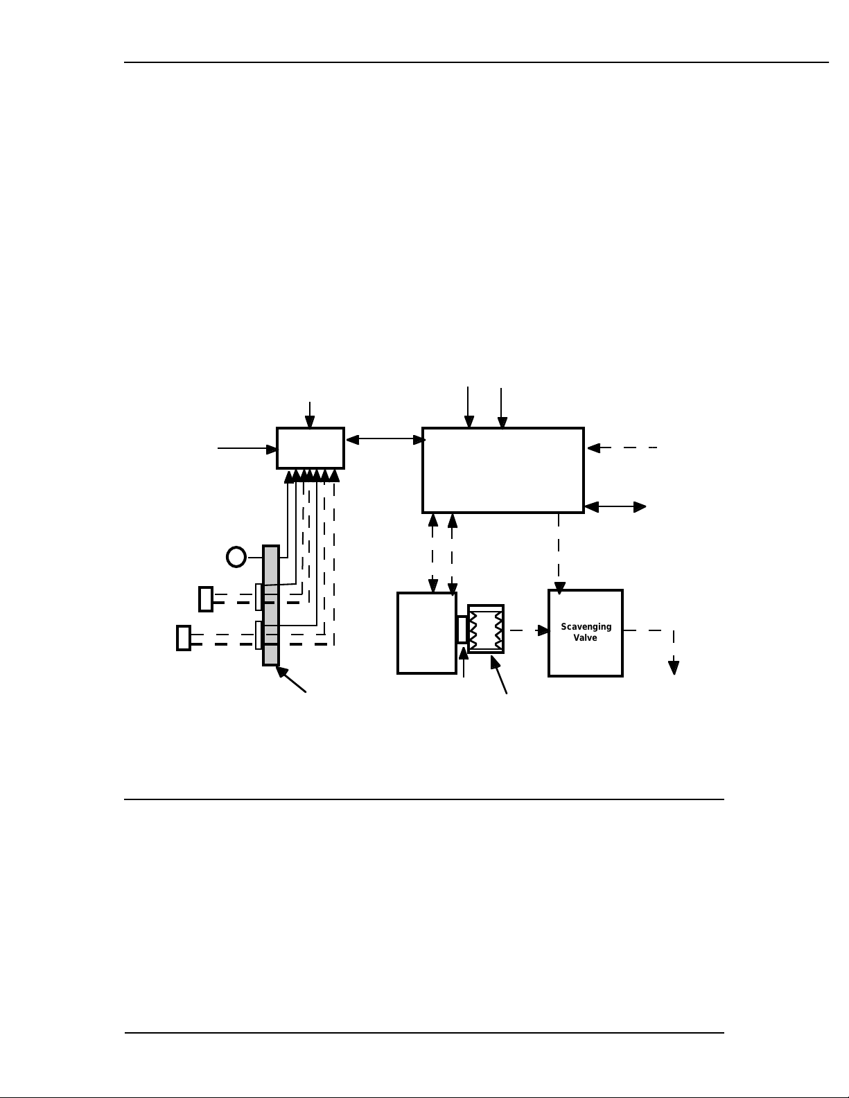
Figure 2-1
7900 Ventilator - Excel SE and Modulus SE Anesthesia System Interface.
User interface settings are stored in non-volatile memory. The user may change
settings with a simple and secure setting sequence. A bellows contains breathing
gasses to be delivered to the patient
Positive End Expiratory Pressure (PEEP) is regulated electronically. Positive pres-
sure is maintained in the breathing system so that any leakage occuring is com-
pensated for by the ventilator to maintain PEEP.
An RS-232 serial digital communications port connects to and communicates with
external devices.
SIB
Board
O2 Flush
O2 Pressure
SIB
C
able
Optional
C
ommunications
Cable
V
entilator
Control
Module
A
C Power
User Inputs
9 Soft keys,
1 knob
3
5 - 100 psi Suppy
Absorber
GMS
MAS
Mk5
A
GS
R
Gas
Scavenging
Valve
A
bsorber
M
anifold
S
IB
Interface
Panel
O
2
S
ensor
F
low
S
ensors
T
o Vacuum
E
xhaust Gas
System
Bellows
2/Theory of Operation
2-2 1503-0151-000 3/27/97
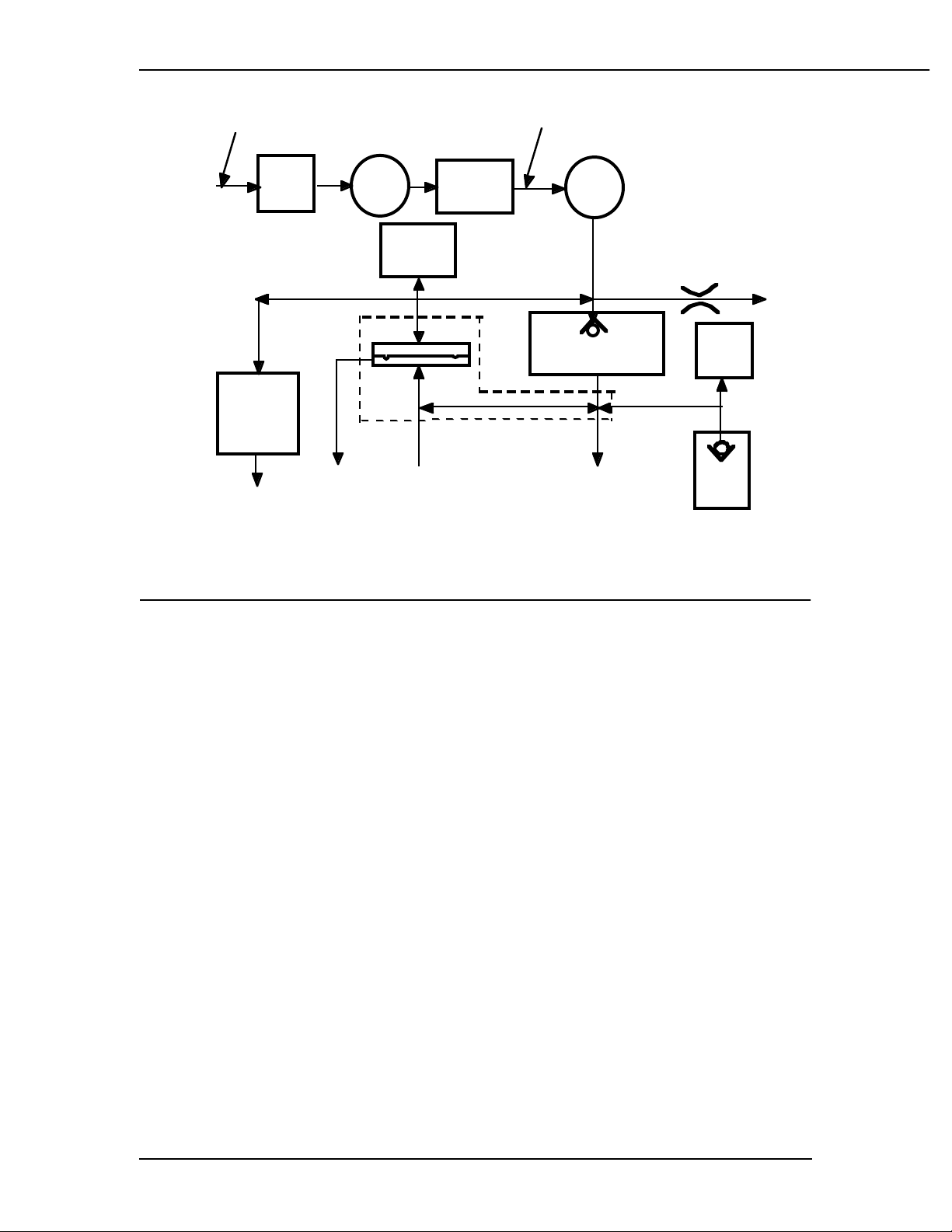
Figure 2-2
7900 Ventilator Operational Block Diagram
Some 7900 Ventilator Features
• No secondary regulator or exhalation solenoids
• An exhalation valve that modulates flow in the pressure mode rath-
er than being just on and off
• Pressure and volume mode selectable by the operator
• All pneumatic components are mounted on a single manifold.
• Eachcomponent is individually accessible fromabove or below the
manifold
• There are no threaded connections to the subassemblies
• Drive gas and bellows pressure relief valve gases are combined
and pass through the ventilator exhalation valve.
• Exhalation valve block is autoclavable
• Scavenging line runs from the ventilator to the Anesthesia Gas
Scavenging Receiver (AGSR) which scavenges both drive gas and
gas released by the bellows pressure relief valve.
• Operates in a "Closed-Loop" configuration during both volume and
pressure modes of operation
• Easier to service, fewer components and improved performance.
Mechanical
Overpressure
Bleed Off
(MOBO)
Pressure
Switch
Drive Gas Check Valve
(DGCV)
Free
Breathing
Valve
Supply
Gas
Hose Manifold
Pressure
Transducer
Flow
Valve
Pressure
Regulator
Inlet
Filter
Gas
Inlet
Valve
(GIV)
35 - 100 psi
Supply 25 psi
25 mm port17 mm port
Exhaust
to Scavenging
SystemExhaust to
Ambient
Bleed Exhaust
to Ambient
Exhalation Manifold
Other manuals for Aestiva 7900 SmartVent
1
Table of contents
Popular Fan manuals by other brands

Kichler Lighting
Kichler Lighting Canfield 300117WH instruction manual

O'Fresh
O'Fresh 077 instruction manual

Kendal Lighting
Kendal Lighting AC-19856 installation instructions

Bosch
Bosch DRR18BS25 User manual and installation instructions

VALBERG
VALBERG BITH 60 X 756C Instructions for use

PROGRESS LIGHTNING
PROGRESS LIGHTNING AirPro P2598 installation manual

STERLING FANS
STERLING FANS SE80TL quick start guide

Hema
Hema 80.01.0054 Instructions for use

Midea
Midea FS40-18BR owner's manual

Lindab
Lindab Plexus Series Installation instruction

Delta Electronics
Delta Electronics KFB1012HHS Dimensions and installation information

Atlas
Atlas Trueridge ALL- WEATHER installation instructions


