DAYTEK LC1508NT User manual


IMPORTANT SERVICE SAFETY INFORMATION
Operating the receiver outside of its cabinet or with its back removed involves a shock hazard. Work on these
models should only be performed by those who are thoroughly familiar with precautions necessary when working on
high voltage equipment.
Exercise care when servicing this chassis with power applied. if carelessly contacted, can cause serious shock or
result in damage to the chassis. Maintain interconnecting ground lead connections between chassis, escutcheon, picture
tube dag and tuner when operating chassis.
When it is necessary to make measurements or tests with AC power applied to the receiver chassis, an Isolation
Transformer must be used as a safety precaution and to prevent possible damage to transistors. The Isolation
Transformer should be connected between the TV line cord plug and the AC power outlet.
It is important to maintain specified values of all components and anywhere else in the received that could cause
a rise in operating supply voltages. No changes should be made to the original design of the receiver.
Components shown in the shaded areas on the schematic diagram and/or identified by in the replacement parts
list should be replaced only with exact factory recommended replacement parts. The use of unauthorized substitute
parts man creates may create shock, fire, or other hazards.
Before returning the receiver to the user, perform the following safety checks:
1. Inspect all lead dress to make certain that leads are not pinched or that hardware is not lodged between the chassis
and other metal parts in the receiver.
2. Replace all protective devices such as non-metallic control knobs, insulating fish papers, cabinet backs, adjustment
and compartment covers of shields, isolation resistor-capacitor networks, mechanical insulators etc.
3. To be sure that not shock hazard exists, a check for the presence of leakage current should be made at each exposed
metal part having a return path to the chassis (antenna, cabinet metal, screw heads knobs and/or shafts, escutcheon,
etc.) in the following manner.
Plug the AC line cord directly into a 110V/220V/240V, AC receptacle. (Do not use an Isolation Transformer
during these checks.) All checks must be repeated with the AC line cord plug connection reversed. (If necessary, a
non-polarized adapter plug must be used only for the purpose of completing these checks.)
PLEASE READ BEFORE ATTEMPTING SERVICE
1. Use an Isolation Transformer when performing any service on this chassis.
2. Never disconnect any leads while receiver is in operation.
3. Disconnect all power before attempting any repairs.
4. Do not short any position of the circuit while the power is on.
5. For safety reasons, replace components any with identical replacement parts (SEE PARTS LIST).
6. Before alignment, warm up the TV for at least 30 minutes.
7. When removing a PCB or related component, after unfastening or changing a wire, be sure to put the
wire back in its original position.
8. Inferior silicon grease can damage IC's and transistors. When replacing IC's and transistors, use only
specified silicon grease. Remove all old silicon when applying new silicon.
9. Before removing the anode cap, discharge eletricity because it contains high voltage.
A. SPECIFICATION
System :NTSC-M
Channel :Antenna 2-69
CATV1-125
IFFrenquencyVideo:45.75MHz
Sound:42.17MHz
Chroma:41.25MHz
Audio output power 10%THD 1WX 2
Antenna Impedance 75Ω(Unbalance)
Power Consumption 36W
Power Supply: AC~100-240V,50/60Hz (Adapter)
DC12V3A(TV)
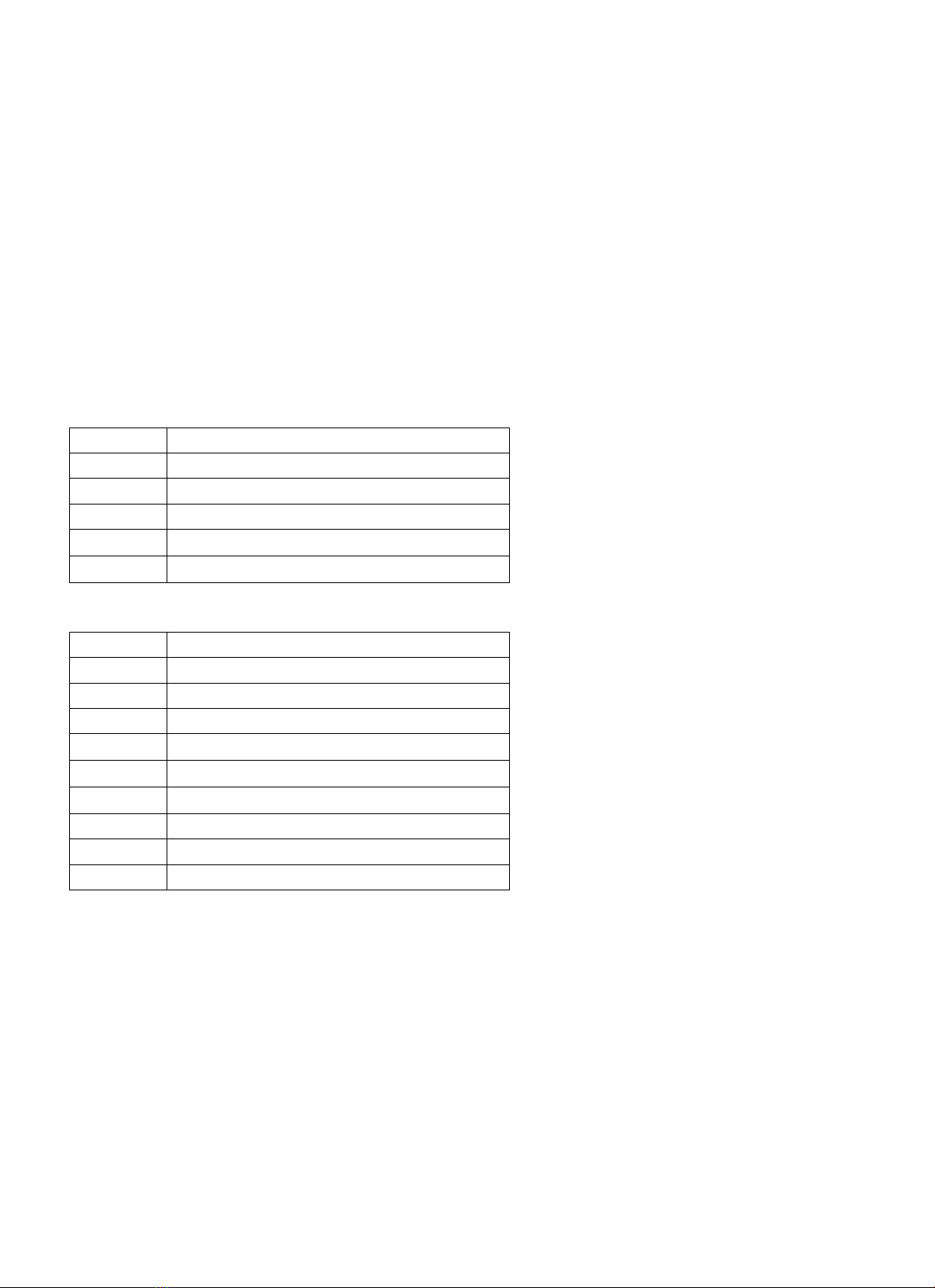
item Port list (KLC-1508US)
1RF cable
2Video and Audio
3 S-Video
4 Headphone audio output
5 DC 12V input
item Port list (KLC-1521US)
1RF cable
2 Y 、Pb /Cb、Pr /Cr
3Audio2(Y、Pb/Cb、Pr/Cr Audio input)
4VGA
5Audio3(PC Audio input)
6Video and Audio1
7 S-Video
8 Headphone audio output
9 DC 12V input
PDF 件以 "PDF 制作工厂" 试用版创建 http://www.fineprint.com

ADJUSTMENT MANUAL
. TEST NOTE
1. Please followthe pointed test steps and choosethe right test equipment to conduct
adjustment, otherwisegood effect of Unit could not be obtained. The unit shouldbe
warmed up for 30 minutes before adjustment and everyparameter should be adjusted
repeatedlytill the optimum value obtained, the pointed voltage value should be ensured
during test to get satisfied test result.
2. Test environment
1) Temperature :15°C-35°C
2) Relative Humidity: 45-75%
3) Air pressure :86-106KPa
3 Test equipments(The following equipment should be calibrated before testing)
1) Computer 1 set
2) Multi-meter (VICTOR VC9801) 1 set
3) Video Signal Generator (Chroma Model 2227/2327) 1 set
4) Color Analyzer (Chroma Model 7120 ) 1 set
5) DDC card (DYNACOLOR, INC D8330) 1 slice
6) TV Video Signal Generator (FLUKE PM54200)1 set
4Factorymode adjustment
4.1 Enter factorymode adjustment
Using the remote control, press Menu button once first ,then press PRE.CH(or named
RECALL) button five times,and you can see manufacture menu on the LCD panel.
4.2 factorymenu operation method
Press the channel +/- button to selection the sub menu of factory menu(including F、E、
UOCⅢ、RGBTemp、Temp), and pressthe vol+ to enterthe sub menu and setting the value.
4.3 exit the factorymenu
Press the MUTE button again and again orturn off the TV, it can exit the factorymenu.
4.4 AGC adjustment
In TVmode,Receive60dB split fieldsignal.Enter factorymode menu UOCⅢ”item,
press”CHAN▽”to select RF AGC”,then useVOL+/- to adjust the item until the voltage ofPin
1 ofN100 to be about 2.5V±0.2V,then noise wave ofthe picture point disappears.
PDF 件以 "PDF 制作工厂" 试用版创建 http://www.fineprint.com

4.5 White calibration adjustment
1Receiveblack or white signalunder AV or PC mode, adjusting brightness and contrast to set
the brightness to 15Nit in dark area and 90 Nit in bright area.
2Adjust white balance.Press“MENU”button once, then press PRE.CH”fivetimes to enter
factorymenu, select Temp”Menu,
Adjust Red 0-100
Green 0-100
Blue 0-100
3Adjusting chromaticitycoordinates of black and white to fit the requirement (X=0.285,
Y=0.293), or plug automatic calibration system to adjust white calibration automatically.
BLOCK DIAGRAM
N401
MAIN IC
TDA15001H
T102
M9352
T101
M3953
N100
Tuner
AGC
SIF
VIF
CVBS,S
-
Video
Audio L,R
KEYB1、B0
IR
PWRON
DDC/HWI2C
BKLON
VCC
-
5Ua
VCC
-
3.3VUSB
VCC+1.8a
VCC+1.8b
Audio
N201
TDA1517
Audio 2
L,R
3.3VSupply
2.5VSupply
VGA
Audio IN
port
Y
Pb
Pr
N303
PI5V330
UOC_R,G,B
YUVHs
YUVVs
M_Rst
M_CLK
M_SDA
M_CS
N501
MST518
Y_G
Pb_B
Pr_R
Port
VG
A
DDC/HWI2C
LCD
PANEL
N301
PI5V330
N302
24LC21
ToN401
SDA
SCL
VGA
-
DAT
VGA
-
CLK
+12V
Supply
Earphone
speaker
LED R,G
+12V
Supply
AU2IN_L,R
AU3IN_L,R
AMP_L
AMP_R
VGA_R,G,B
VGA_Hs,Vs
VCC
-
PAN
Y,Pb/Cb,Pr/Cr
(Onlyfor KLC
-
1521US)
Signal Block Diagram
PDF 件以 "PDF 制作工厂" 试用版创建 http://www.fineprint.com


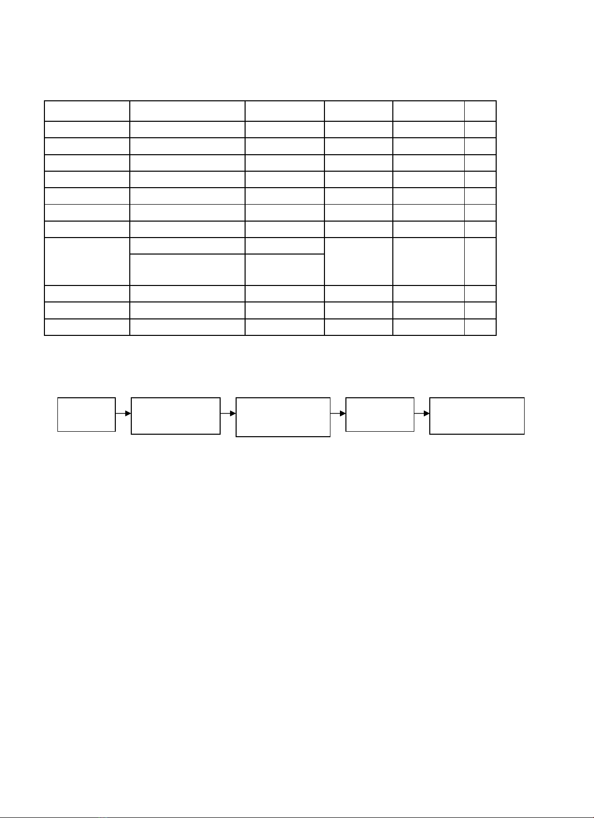
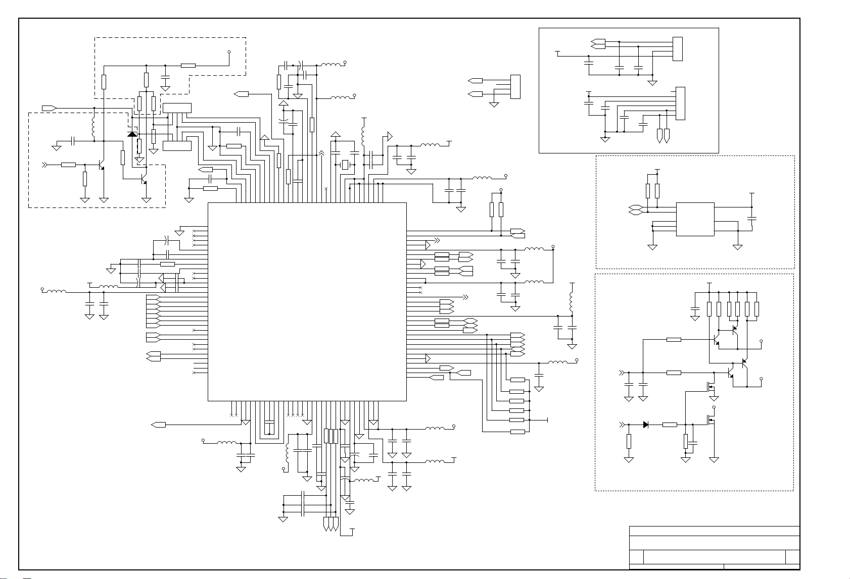
Trouble Shooting
Key IC list
Item Type Maker Package Circuit No.
Qty.
1TDA15001H1 Philips QFP128 N401 1
2 MST518 MSTAR PQFP160
N501 1
324LC32A MICROCHIP
SOIC-8 N402 1
424LC21AMICROCHIP
SOIC-8 N302 1
5MP1410ES-SOIC-8
MPS SOIC-8 N801,N802
2
6FDS9435A FAIRCHILD
SOIC-8 N803 1
8 TDA1517 PHILIPS SIL9MPF N200 1
FSAV330 FAIRCHILD
9
(onlyfor
KLC-1521US)
TS5V330 TI TSSOP-16
N301,N303
2
11 1117-3.3V 1117 serial SOT223 N804,N806
2
12 1117-2.5V 1117 serial SOT223 N805 1
14 Tuner AFT1/L301 Qingjia N100 1
Start order
1)Verify the state ofTV set.Please switchthe TV on ,thenverify the LED color. Redis
standby state and green is working state.
2)Checking Supply Power.If the color of LEDis yellow,the power supply for signal board 。
N801 supply 5V and N802 supply 3.3V(KLC-1508US,KLC-1521US),N804、N806 supply 3.3V
power(Test the PIN 2).N805 supply 2.5V(Test the PIN 2),D803 supply 8.3V,V401 and V402
supply 1.8V. All these are for main IC N401,N501.
3)After turning on the power, if blank screen appears (no back light lamp), just
press POWER button several times, if blankscreen still there.Check if the voltageof
every power supply is normal.
4)Check if the crystaloscillator X501(14.318180MHz) X401(24.576MHz) oscillate or not,
and oscillate frequency is right or not.
5)Back light control signal (BKLON) of XS801 has high level (about 2.5V)
or not, if not, check whether fault soldered or short circuit happened。
6) If back lightlampis on whilethere is no display,check N407and N501 sresetcircuit
and the output oftheoscillator to confirmthe CPU andSCALER are working or not.IfRGB
is abnormal,check N501;If RGB is working correctly and the other channel is
abnormal ,please check N501.
Turn on the
power
N401RESETand
IO port initialize
N501electrify,
reset, initialize
Turn onback
light lamp
Successful start
and LCD display
PDF 件以 "PDF 制作工厂" 试用版创建 http://www.fineprint.com


5
5
4
4
3
3
2
2
1
1
DD
CC
BB
A
A
VCC_3.3U is for UOC III 3.3V
VCC_8U is for UOC audio 8V
VCC_5Ua is for UOC and TUNER analog
VCC_CORE is for MST Vcore
VCC_OP is for MST Voutput
VCC_ADC is for MST Vadc
VCC_AMPLL is for MST Vmpll
VCC_ADPLL is for MST Vadpll
POWER
TO POWER
VCC_5Usb is for 5V STANDBY
R809 R805 R807
390K
5.0V
410K
VCC_PAN is for Pannel 5V or 3.3V
SET
2K15K
3.3V
30K 1.5K
C842 close to N805
NC
NC
NC
LC-TM1509S 1.0
<Title>
A3
5 5Wednesday, March 08, 2006
Title
Size Document Number Rev
Date: Sheet of
VCC_3.3
VCC_3.3Usb
VCC_12V
VCC_5V
VCC_5Ua
VCC_Usb
VCC_8U
VCC_OP
VCC_ADC
VCC_AMPLL
VCC_ADPLL
VCC_Usb
VCC_5V
VCC_LP
VCC_12V
VCC_PAN
VCC_5VVCC_COREVCC_Usb
VCC_Usb
VCC_Usb
VCC_12V
VCC_5U
V804
BC847
R822 NC/1K
L803 15uH
C841
10u/16V
+
C830
47u/16V
D803
8V
R810
3.3K
XS802
NC
1
2
3
R803
30K
R805
15K
N801 MP1410ES
1
2
3
4 5
6
7
8
BS
IN
SW
GND FB
COMP
EN
N/C
L813 FB
C859
10u/16V
V861
NC/BC847
R830 NC/0
F801
2A
+
C808
10u/16V
XP801
1
2
3
4
5
6
C847
10u/16V
D801
FM5820
R824 NC/1K
V862
NC/BC847
C825
180p
L804 FB
+
C819 470u/16V
R804
1.5K
C853
10u/16V
V802
NC/BC847
C8200.22/16V
R820
10K
C802
0.1u/25V
D802
FM5820
L805FB
L801 FB
N860 NC/9435A
1
2
3
4
8
7
6
5
D
D
D
G
S
S
S
S
C852
0.1u/25V
C814
3.3n/50V
R811 3.3K
R821A 1K
V805
BC847
L810 FB
C804
0.22/25V
C8210.22/25V
C813
10n
R812 22K
V803
BC847
C810
0.22/16V
N803 9435A
1
2
3
4
8
7
6
5
D
D
D
G
S
S
S
S
C860
NC/0.1
L820FB
R802
10K
R823A NC/1K
L807 FB
+
C809
470u/16V
L815
15uH
C824
0.1
L809 FB
R821 NC/1K
C855
10u/16V
C815 180p/50V
R860 NC/3.3K
+
C827
470u/16V
L811 FB
C843
10u/16V
R807
2K
+
C816
470u/16V
R826
10K
R801 390K
C836
0.22
C807
0.1
N802
MP1410ES
1
2
3
4 5
6
7
8
BS
IN
SW
GND FB
COMP
EN
N/C
C842
10u/16V
XS803
NC
1
2
3
4
1
2
3
4
+
C803
470u/25V
R808 10K
R815
510
R823 470/NC
C840
10u/16V
R861
NC/3.3K
N806
1
3 4
2
GND
IN VO
VO
R831
0/NC
C851
10u/16V
C857
10u/16V
R825
NC/10K
L812 FB
C817
10u/16V
C838
10u/16V
R806
10K
C835
0.1
N805
BA18BC0FP
1
3 4
2
GND
IN VO
VO
N804
BA18BC0FP
1
3 4
2
GND
IN VO
VO
R809
470K
C823
10n
L814 FB/1206
C826
3.3n
L808 FB
C828
10u/16V
BKLBT 2
PWRON 2,4
PWRON 2,4
BKLON 2
PDF !" "PDF #$%& "'()*+ http://www.fineprint.com
DAYTEK
5
5
4
4
3
3
2
2
1
1
DD
CC
BB
A
A
SPEAKER_R
SPEAKER_L
TUNER & AMP
Audio AMP
TUNER
NC
NC
NC
ONLY FOR
KLC-1521US
LC-TM1509S <RevCode>
<Title>
A3
4 5Wednesday, March 08, 2006
Title
Size Document Number Rev
Date: Sheet of
VCC_12V
VCC_12V
VCC_12V
VCC_5Ua
VCC_5Ua
VCC_5UA
VCC_5UA
VCC_5U
V202
BC847
C370
2.2
R212
470K
C313 1u/10V
R307
82
XS201A
NC
1
2
C201
0.1
V100
C388
+
C374
22u/16V
+
C375
22u/16V
XS305
HEADPHONE
4
5
3
2
7
8
1
R213
1K
R314
10K
C107
0.01
R206
10K
L100
47uH
R308 100
R373
10K
N100
1
2
3
4
5
6
7
8
9
10
11
12
13
14
15
AGC
TU
AS
SCL
SDA
NC
VCC
AFC
VT
GND
IF
12
13
14
15
R313
1K
R377
100
R376
100
R211
10K
R208
10K
R105
4.7K
L101 FB
R107
33
V318
BAV99
R214
10K
R209
NC/10K
R372
10K
2
34
1
XS302 S-VIDEO
4
3
2
1
5
6
7
R311
1K
XS200
D2006-2
1
2
C204
0.1/50V
C371
2.2
R100
10K
R207
220K
D200
1N4148
+
C222
470u/16V
R374
10K
R375
10K
R210
NC/10K
C310
0.1
+
C203
470u/16V
C106
10u/16V
C312
100p
C372
100p R104
1K
R201
2.2K
C104
0.01
R106
1.2K
+
C221
470u/16V
XS301
AUDIO IN
1
3
2
+
C210
4.7u/25V
+
C109
100u/16V
C377
100
R370
1K
L103
47uH
V319
BAV99
R203
2.2K
C309
100p
R102100
R108
470
C311 1u/10V
C103
0.01
R103
100
XS304 VGA_AUDIO_IN
5
4
2
3
7
8
1
C308 0.1
R371
1K
R202
2.2K
V203
BC857
D201
1N4148
C205
0.1
R309
82
C102
220u/16V
R109
100
XS201
D2006-2
1
2
C100
10u/16V
R200
2.2K
C101
0.01
L102
12uH
C314
100p
C105
0.01
V201
NC/BC847
C307
100p
C211
0.1
XS200A
NC
1
2
C373
100p
+
C207
47u/16V
R310 100
C376
100
R312
10K
C200
0.1
N200 TDA1517
1
2
3
4
5
6
7
8
9
-INV1
SGND
SVRR
OUT1
PGND
OUT2
Vp
M/SS
-INV2
R101100
R219
10
R204
10
SV1_Y 2
SV1_C 2
AMP_L 2AMP_R2
MUTE2
PWRON2,5
SDA_HW2,3
AGC2
IF 2
SCL_HW2,3
AU3IN_R 2
AU3IN_L 2
AU2IN_L 2
AU2IN_R 2
PDF !" "PDF #$%& "'()*+ http://www.fineprint.com
DAYTEK
5
5
4
4
3
3
2
2
1
1
DD
CC
BB
A
A
L->DDC
SCALER INPUTPORT
H->HW
FOR COLOR
AUTO_ADJUST
NC
NC
NC
NC
NC
ONLY FOR
KLC-1521US
ONLY FOR
KLC-1521US
UOC_R/G/B connect to
R329/R330/R331 directly
only for KLC-1508US
LC-TM1509S 1.0
<Title>
A3
3 5Wednesday, March 08, 2006
Title
Size Document Number Rev
Date: Sheet of
A_VSYNC
A_B
A_HSYNC
A_HSYNC A_G
A_R
A_VSYNC
U_G
M_B
M_G
U_R M_R
U_B
UOC/YPbPr
YUVHSYNC
DDC_PWR
PB/Cb
CLK_DDC_VGA
DAT_DDC_VGA
DAT_DDC_VGA
CLK_DDC_VGA
PR/CR
Y
YUVVSYNC
VCC_5D
VCC_5D
VCC_Usb
VCC_USB
VCC_USB
VCC_USB
VCC_5D
VCC_USB
VCC_Usb
VCC_5Ua
VCC_USB
VCC_USB
VCC_USB
VCC_5UA
VCC_USB
VCC_USB
V306
BAV99
C336
0.1
N303
PI5V330A
1
2
3 4
5
6
7
8
9
10
11
12
13
14
15
16
IN
S1A
S2A DA
S1B
S2B
DB
GND
DC
S2C
S1C
DD
S2D
S1D
/EN
VCC
C32210
R502
2K
R441
2.2K
C306 1u
V305
BAV99
R342 75
L302 BEAD
V315
BAV99
R332 220K
C304 1u
R327 75
L301 BEAD
R345 100
R503
NC
C340 10
C335
0.1
C32110
R355 1.2K
R330
100
R325
1K
R338
2K
C350 NC
C337
10u/16V
C305
100
L303 BEAD
V316
BAV99
V301
BAV70
1
2
3
C531 .047
V309
BAV99
C206
0.1
R356 1.2K
R380
100
XS505
CON2
1
2
V312
BAV99
R305
47K
L306 BEAD
R304
1K
R346 100
L304 BEAD
C533 .047
R329
100
R357 1.2K
L305 BEAD
R382 100
C352 10u
C301
100
C32310
V317
BAV99
N302
24LC21
1
2
3
45
6
7
8NC
NC
NC
GNDSDA
SCL
VCLK
VCC R354
100
N301
PI5V330A
1
2
34
5
6
7
8
9
10
11
12
13
14
15
16
IN
S1A
S2ADA
S1B
S2B
DB
GND
DC
S2C
S1C
DD
S2D
S1D
/EN
VCC
C537 1n
V308
BAV99
C351 220P
R3581.2K
C538 .047
R381
100
C342 10
V311
BAV99
C303
100
C532
0.001
R341 75
V307
BAV99
C378
0.1
R344 100
R427
10K
R301
82
V310
BAV99
R343 75
R3591.2K
R32875
R383 100
C535 .047
R504 NC
XS309
AV/YPbPr/YCbCr
9
2
1
13
4
11
7
8
3
5
12
10
6
R306
1K
C302 0.1
R3621.2K
R353
10K
XS308
DSUB-15
1
6
2
7
3
8
4
9
5
11
12
13
14
15
1016
17
C536 .047
C353 10u
R426
100
R351 2.2K
R335 1K
C534 .047
C34110
R303
47K
C333
0.1
C332
10u/16V
R302
100
R339
4.7K
C354 10u
XS666
1
2
3
4
1
2
3
4
R501
2K
R340
4.7K
R505 NC
R32675
R331
0
C334 NC
R337
10K
VGA_G 1
VGA_B 1
VGA_VSYNC 1
VGA_R 1
VGA_HSYNC 1
UOC_G2
Pb_B 1
Pr_R 1
UOC/YUV2
YUV_HSYNC 1
UOC_R2
Y_G 1
UOC_B2
YUVHSYNC
2
VIDEO1 2
AU1IN_L 2
AU1IN_R 2
DDC/HWI2C 2
SDA_HW 2,4
SCL_HW 2,4
YUV_VSYNC 1
YUVVSYNC
2
RX
TX
Y_SOG 1
VGA_SOG 1
PDF !" "PDF #$%& "'()*+ http://www.fineprint.com
DAYTEK
5
5
4
4
3
3
2
2
1
1
DD
CC
BB
A
A
UOC III
Face Down version
NVRAM
KEYB,IR
PWRON_RST (IO mode)
SCART0_IN
SCART1_IN
NC
NC
NC
NC
NC
NC
ONLY FOR LC-TM2018S
ONLY FOR LC-TM2018S
LC-TM1509S 1.0
<Title>
A3
2 5Wednesday, March 08, 2006
Title
Size Document Number Rev
Date: Sheet of
IR
DECDIG
UOC_RST
SYS
UOC_RST
DECDIG
SYS
VCC_+1.8a
VCC_3.3Usb
VCC_8U
VCC_5UA
VCC_+1.8b
VCC_3.3Usb
VCC_+1.8b
VCC_3.3Usb
VCC_5Ua
VCC_3.3Usb
VCC_Usb
VCC_+1.8b
VCC_+1.8a
VCC_+1.8b
VCC_+1.8b
VCC_3.3Usb
VCC_5Ua
VCC_5Ua
VCC_3.3Usb
VCC_5Ua
VCC_5Ua
VCC_3.3USB
VCC_3.3Usb
VCC_3.3Usb
VCC_3.3Usb
VCC_5V
VCC_5V
C496
1u
C439
NC/0.01
C489
0.01
R423
100
C480
0.22
C438
NC/0.01
R440100
C454 1
X401
24.576MHz
R128
NC/47
C433
22p
C488
10u/16V
+
C455 10u/16V
C437
NC/0.01
R472
3.3K
R110
1.2K
R483 4.7K
R462
4.7K
L421
FB
R430 390
L405 FB
C461
47P
R439 100
R127
NC/47
L401
NC/FB
C445
10u/16V
L414 FB
V404
PMBTA64
R42447K
R116
47K
C467
0.1
R490
15K
L422 FB
C459
10u/16V
C444
22p
R470 4.7K
C483
10u/16V
R438100
L411
FB
C448
10u/16V
R475 4.7K
R465 3.3K
T101
M3953M
12345
C478
0.1
V405
BSH103
C111
0.1
V402
PMBTA64
+
C425
220u/16V
T102
M9352M
12345
R117
100K
C435
NC/0.01
C491
0.01
L412 FB
R467
1K
V406
BSH103
C458
0.01
R4854.7
UOC III
Hercules
N401
UOC III
1
2
3
4
5
6
7
8
9
10
11
12
13
14
15
16
17
18
19
20
21
22
23
24
25
26
27
28
29
30
31
32
33
34
35
36
37
38
39
40
41
42
43
44
45
46
47
48
49
50
51
52
53
54
55
56
57
58
59
60
61
62
63
64
96
95
94
93
92
91
90
89
88
87
86
85
84
83
82
81
80
79
78
77
76
75
74
73
72
71
70
69
68
67
66
65
128
127
126
125
124
123
122
121
120
119
118
117
116
115
114
113
112
111
110
109
108
107
106
105
104
103
102
101
100
99
98
97
P1.5/TX
P1.4/RX
P1.2/INT2
VSSC3
VDDC3
P2.5/PWM4
P2.4/PWM3
VSSC1/P
P3.3/ADC3
P3.2/ADC2
DECV1V8
VDDC1(1.8)
P3.1/ADC1
P3.0/ADC0
P2.3/PWM2
P2.2/PWM1
P2.1/PWM0
P2.0/PMW
VDDP(3.3V)
P1.7/SDA
P1.6/SCL
P1.3/T1
P0.0
P0.1
P0.2
P0.3
P0.4
VSSC2
VDDC2
P1.1/T0
P1.O/INT1
INT0/P0.5
VDDadc(1.8)
VSSadc
VDDA2(3.3V)
VDDA(1.8V)
GNDA
NC
VREFAD_POS
VREFAD_NEG
VDDA1(3.3V.)
BO
GO
RO
BLKIN
BCLIN
VP3
GND3
B/PB-3
G/Y-3
R/PR-3
INSSW3
VOUT(SWO1)
UOUT(INSW-2)
YOUT
YSYNC
YIN(G/Y-2/CVBS/Y-X)
UIN
VIN(R/PR-2/C-X)
VDDcomb
VSScomb
HOUT
FBISO/CSY
SVM
SSIF/REFOUT
AUDIOIN5L
AUDIOIN5R
AUDOUTSL
AUDOUTSR
DECSDEM
AMOUT/QSSO/AUDEEM
GND2
PLLIF
SIFAGC/DVBAGC
DVBO//IFVO/FMRO
NC
VCC8V
NC
VP2
SVO/IFOUT/CVBSI
AUDIOIN4L
AUDIOIN4R
CVBS4/Y4
C4
AUDIOIN2L/SSIF
AUDIOIN2R
CVBS2/Y2
AUDIOIN3L
AUDIOIN3R
CVBS3/Y3
C2/C3
AUDOUTLSL
AUDOUTLSR
AUDOUTHPL
AUDOUTHPR
CVBSO/PIP
VSSP2
VSSC4
VDDC4
VDDA3(3.3V)
NC
NC
NC
NC
NC
XTALIN
XTALOUT
VSSA1
VGUARD/SWIO
DECDIG
VP1
PH2LF
PH1LF
GND1
SECPLL
DECBG
AVL/EWD
VDRB
VDRA
VIFIN1
VIFIN2
VSC
IREF
GNDIF
DVBIN1/SIFIN1
DVBIN2/SIFIN2
AGCOUT
EHTO
C112 153
L407 FB
L402
FB
C110
NC/0.1
C182 0.01
V401
BC847
C490
10u/16V
L404 FB
C495
10u/16V
C447
0.01
V110
BC847
C440
NC/0.01
R466 3.3K
C427
0.01
D110
BA792
XS306
CON6
1
2
3
4
5
6
C494
0.22
R459 100
C46810u/16V
C486
0.1
R468 1K
C466
0.01
V403
BC847
C469 0.01
C471
1n
R489
1K
R4874.7
L403 FB
R474 4.7K
C4760.1
V111
BC847
R425
1K
L110
560nH
C485
10u/16V
C4730.1
R114
100
R481
4.7K
+
C43010u/16V
R482
4.7K
C463
47P
L420 FB
C432
0.22
R126 0
L413 FB
C493
2.2u/16V
C446
0.01
C474
0.1
+
C475
100u/10V
C434
NC/0.01
C470
10u/16V
R473 4.7K
R4884.7
C431
0.22
C465
10u/16V
R421
12K
C462
47P
+
C472100u/10V
R460 100
R111
1.2K
C436
NC/0.01
D401
1N4148
C482
0.22
L410 FB
R463 4.7K
C452 1n
C456 0.01
R491
150K
+
C451
4.7u/16V
R4844.7K
L406
FB C487
0.22
C492
10u/16V
XS307
CN4
1
2
3
4
1
2
3
4
R112
10K
R471
3.3K
C426
1u
R4864.7
L423 FB
C453 0.1
C457 1u
C481
10u/16V
R464 4.7K
N402
24LC32
5
6 8
4
1
2
3
7
SDA
SCL VCC
GND
NC0
NC1
NC2
WP
C428
0.01
R125 0
C484
0.22
XS888
CN4
1
2
3
4
1
2
3
4
R461
4.7K
R113
1.2K
R115
39K
KEYB0
LEDR
YUVHSYNC
3
AU1IN_L3
BKLBT 5
SDA_HW 3,4
UOC_R3
M_SDA 1
SCL_HW 3,4
BKLON 5
M_CS 1
UOC_B3
PWRON 4,5
M_RST 1
UOC_G3
IR
SV1_Y4
AU1IN_R3
VIDEO13
AGC4
LEDG
IF4
KEYB1
M_CLK 1
KEYB1
KEYB0
SDA_HW3,4
SCL_HW3,4
UOC/YUV 3
DDC/HWI2C 3
AU3IN_L3
AU3IN_R3
AMP_L4
AMP_R4
MUTE 4
RX
TX
SV1_C4
YUVVSYNC
3
M_INT 1
LEDRLEDG
SDA_HW
SCL_HW
AU2IN_L3
AU2IN_R3
PDF !" "PDF #$%& "'()*+ http://www.fineprint.com
DAYTEK
1
1
A
A
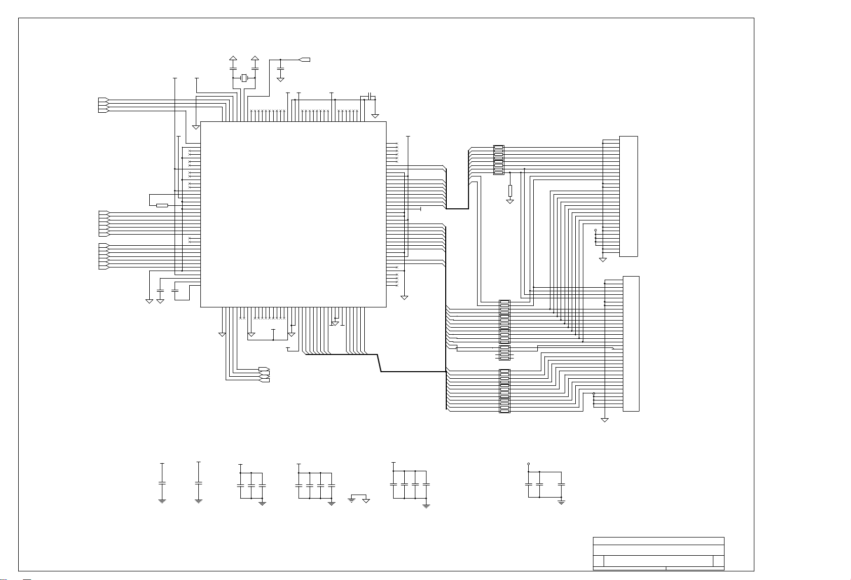
MST518_PQF160
TTL_EVEN_PIXEL
Note:R11 - R24 and R518 - R527 should
place close to N501
LVDS
LC-TM1509S
SCALER_TSU36AWVJ
Custom
1 5Wednesday, March 08, 2006
Title
Size Document Number Rev
Date: Sheet of
LVA1M
LVB0M
DBO6
LVB1M
LVB0P
DBO4
LVB2P
LVB1P
LVB2M
DBO5
LVA3P
LVA0P
DGE7
DGE3
LVA2P
DGE4
DBE1
DBE3
DGE3
DBE6
DGE6
LVA3M
DBE0
DBE5
DBE4
DBE7
LVA1P
DBE2
LVACKM
DGE5
DBO6
DRE4
DRE0
DVS
DBO3
DHS
DGE1
DRE7
DHS
DCLK
DBO7
DGE1
DBO2
DEN
DRE3
DRE3
DBO4
DVS
DRE7
DRE5
DRE1
DBO5
DGE0
DRE6
DGE0
DGE2
DGE2
DRE2
DRE1
DRE0
DRE4
DRE5
DBE1
DBE3
DBE4
DBE5
DBE6
DBE7
DBE2
DBE0
DGE7
DGE6
DGE5
DGE4
DRE6
DEN
DBO7
DCLK
DBO3
DBO2
DRE2
LVBCKP
LVBCKM
LVB3P
LVB3M
LVA0M
LVACKP
LVA2M
VCC_ADPLL VCC_AMPLL VCC_ADC VCC_CORE VCC_OP
VCC_OP
VCC_ADC
VCC_OP
VCC_OP
VCC_AMPLL
VCC_OP
VCC_ADPLL
VCC_CORE
VCC_OP
VCC_CORE
VCC_CORE
VCC_PAN
VCC_PAN
VCC_PAN
VCC_CORE
C501
22p
C511
0.1u
RP517
47R
RP514
47R
C513
0.1u
C518
0.1u
RP513
47R
C514
0.1u
N501
15
16
17
18
19
20
21
22
23
24
25
26
27
28
29
30
31
32
33
34
35
36
37
38
39
40
41
42
43
44
45
46
47
48
49
50
51
52
53
54
55
56
57
58
59
60
61
62
63
64
65
66
67
68
69
70
71
72
73
74
75
76
77
78
79
80
120
119
118
117
116
115
114
113
112
111
110
109
108
107
106
105
104
103
102
101
99
98
97
96
95
94
93
92
91
90
89
88
87
86
85
84
83
82
81
100
160
159
158
157
156
155
154
153
152
151
150
149
148
147
146
145
144
143
142
141
140
139
138
137
136
135
134
133
132
131
130
129
128
127
126
125
124
123
122
121
1
2
3
4
5
6
7
8
9
10
11
12
13
14
RB[0]
RB[1]
RB[2]
RB[3]
VDDC
GND
GND
VDDP
RB[4]
RB[5]
RB[6]
RB[7]
NC
NC
DDC_DAT
DDC_CLK
DDCROM_CLK
DDCROM_DAT
HWRESET
XIN
XOUT
AVDD_MPLL
GND
HSYNC0
VSYNC0
HSYNC1
VSYNC1
GND
R+
R-
GND
G+
G
AVDD
B+
B-
GND
CLK+
CLK-
AVDD
REXT
AVDD_PLL
GND
AVDD
GND
BIN1
BIN1M
SOGIN1
GIN1
GIN1M
RIN1
RIN1M
NC
NC
BIN0M
BIN0
GIN0M
GIN0
SOGIN0
RIN0M
RIN0
GND
AVDD
RMID
REFP
REFM
GA[5]
GA[4]
GA[3]
GA[2]
GA[1]
GA[0]
VDDC
GND
GND
VDDP
BA[7]
BA[6]
BA[5]
BA[4]
BA[3]
BA[2]
BA[1]
BA[0]
VDDC
GND
VDDP
VD7
VD6
VD5
VD4
VD3
VD2
VD1
VD0
VCLK
GND
VDDP
PWM1
PWM0
INT
SCL
SDA
CS
GND
GND
NC
NC
NC
NC
NC
NC
BB[5]/LVB0M
BB[4]/LVB0P
GND
VDDP
BB[3]/LVB1M
BB[2]/LVB1P
BB[1]/LVB2M
BB[0]/LVB2P
LDE/LVBCKM
OCLK/LVBCKP
LVSYNC/LVB3M
LHSYNC/LVB3P
VDDC
GND
GND
VDDP
RA[7]/LVA0M
RA[6]/LVA0P
RA[5]/LVA1M
RA[4]/LVA1P
RA[3]/LVA2M
RA[2]/LVA2P
RA[1]/LVACKM
RA[0]/LVACKP
GND
VDDP
GA[7]/LVA3M
GA[6]/LVA3P
NC
GND
NC
NC
NC
NC
GND
BYPASS
BB[6]
BB[7]
GB_0
GB_1
GB_2
GB_3
GND
VDDP
GB_4
GB_5
GB_6
GB_7
C528
0.1u
XS501
CON32
1
2
3
4
5
6
7
8
9
10
11
12
13
14
15
16
17
18
19
20
21
22
23
24
25
26
27
28
29
30
31
32
1
2
3
4
5
6
7
8
9
10
11
12
13
14
15
16
17
18
19
20
21
22
23
24
25
26
27
28
29
30
31
32
RP510
NC/47R
C517
0.1u
C519
0.1u
C500
1u
C503 0.1
R507 390
R510
0/NC
XS502 NC
CON36
1
2
3
4
5
6
7
8
9
10
11
12
13
14
15
16
17
18
19
20
21
22
23
24
25
26
27
28
29
30
31
32
33
34
35
36
1
2
3
4
5
6
7
8
9
10
11
12
13
14
15
16
17
18
19
20
21
22
23
24
25
26
27
28
29
30
31
32
33
34
35
36
C510
0.1u
C527
0.1u
RP518
47R
C506
0.1
RP515
47R
X501
14.318MHz
RP511
NC/47R
C520
0.1u
C516
0.1u
RP516
47R
C502
22p
C508
0.1u
C530
0.1u
C509
0.1u
RP512
NC/47R
C515
0.1u
C505
0.1
C512
0.1u
YUV_HSYNC3
M_CLK 2
YUV_VSYNC3
M_RST 2
M_SDA 2
M_INT 2
VGA_HSYNC3
M_CS 2
VGA_VSYNC3
GND3
GND3
Y_G
3
GND
3
Pr_R
3
Pb_B
3
Y_SOG
3
VGA_B3
GND3
GND3
GND3
VGA_G3
VGA_R3
VGA_SOG3
PDF !" "PDF #$%& "'()*+ http://www.fineprint.com
DAYTEK
This manual suits for next models
2
Table of contents


