DE RIGO refrigeration SAPPHIRE M1 User manual
SAPPHIRE
USE AND MAINTENANCE MANUAL
Read carefully and preserve together with the counter
Manual VZST11961
D-G3813
Revision 00
Revision date 04/ 10/ 2013
EN
2
De Rigo Refrigeration s.r.l.
3
De Rigo Refrigeration s.r.l.
TABLE OF CONTENTS
General Features.................................................. 4
Position of main components ....................... 4
Serial number plate....................................... 5
Important installation conditions ........................... 6
Warnings ............................................................. 8
Installation recommendations....................... 8
General recommendations ........................... 9
Precautions for use and minor maintenance ....... 10
Loading products for display ......................... 10
Replacing light bulb .................................... 11
Positioning display shelves ........................ 13
Electric components .......................................... 14
Lighting ...................................................... 14
Electric panels ........................................... 14
Technical information ......................................... 16
Technical documentation inserted in counters .... 16
Technical data .................................................... 17
Emergency situations .................................................... 18
We recommend reading the contents of this manual and keeping it together with the counter. The
manufacturer will not be held liable for property damage and/or personal harm due to failure to comply
with the instructions contained in this manual. It is therefore recommended that whoever uses this
counter carefully read the use and maintenance manual.
The refrigerated counters which the following use and maintenance instructions refer to comply with
Standard ISO 23953-2 - Refrigerated display cabinets - and apply the HACCP Foodstuff and relative
control system safety standards.
The products are manufactured in accordance with the following standards and their specific updates:
EN 60335-2-24 (1994) + A51(’95) + A52(’96) + A53(’97), EN 60335-1 (1988) + A2(’88) + A5(’89) + A6
(’89) + A51(’91) + A52(’92) + A53(’92) + A54(’92) + A55(’93) + A56(’95), IEC 60335-2-24 (1997) + A1
(’98), IEC 60335-1 (1991) + A1(’94)
Description of the product
Installation of the product
Maintenance and use of the product
Lighting and electric controllers which
can be configured on the product
Technical data of the product
Management of emergency situations
The gas is present in the appliance according to a minimum amount prescribed by
regulations on flammable gases, but necessarily involves greater precautions in han-
dling the appliance especially when working on the refrigerating system.
This appliance with R290 flammable refrigerant gas (Propane) will be identified with the following label
shown on the data plate and on several sensitive components.
4
De Rigo Refrigeration s.r.l.
SAPPHIRE
GENERAL FEATURES
The Sapphire is a refrigerated plug-in counter for the display and sale of meat, cold cuts, dairy products,
fruit and vegetables with ISO 23953-2 class 3 climate operating conditions.
The maximum depth of the counter when using 450 mm shelves is equal to 850 mm and is available in
1250, 1875 and 2500 mm lengths. It provides the use of swinging doors that ensure good energy sav-
ings.
The counter has a built-in hermetic condensing unit and is equipped with a compressor that comes into
operation as soon as the plug is connected to the power outlet.
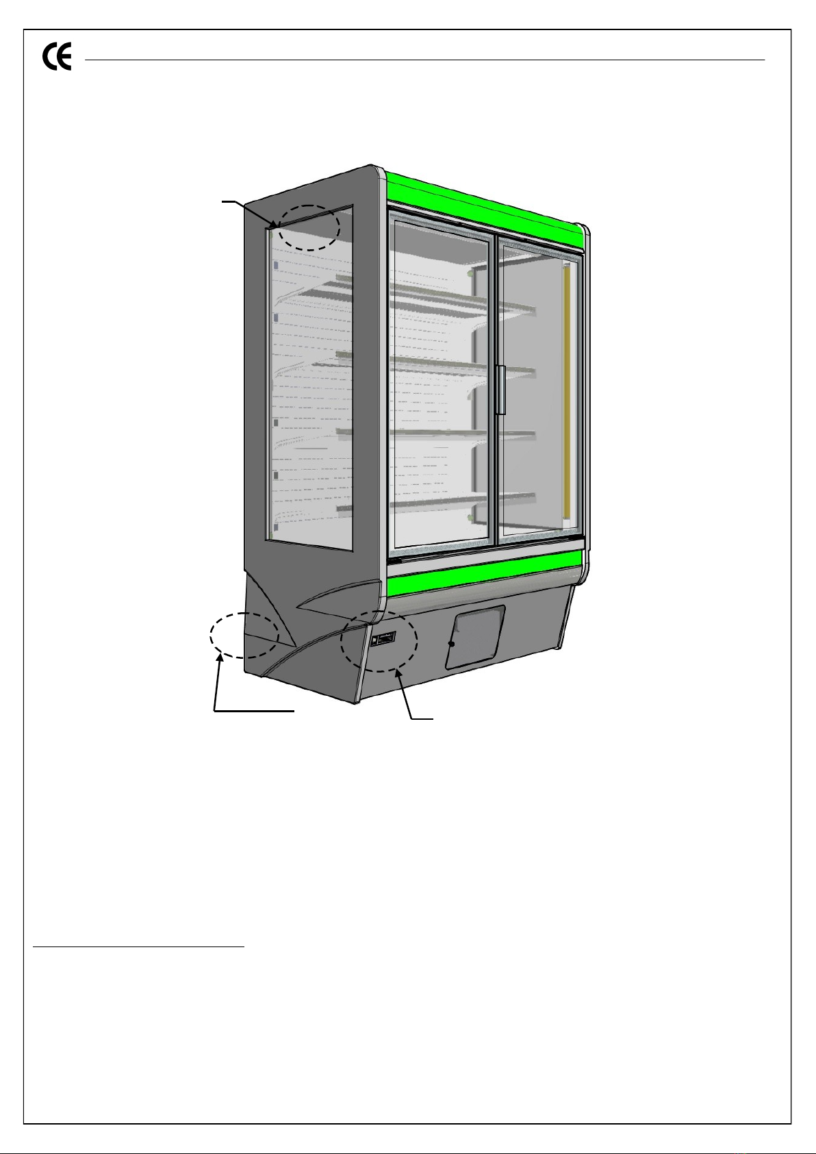
Position of main components
1. Electric panel
2. Serial number plate
3. Equipotential point
4. Access to the condenser for cleaning
4
3 behind 1
2
5
De Rigo Refrigeration s.r.l.
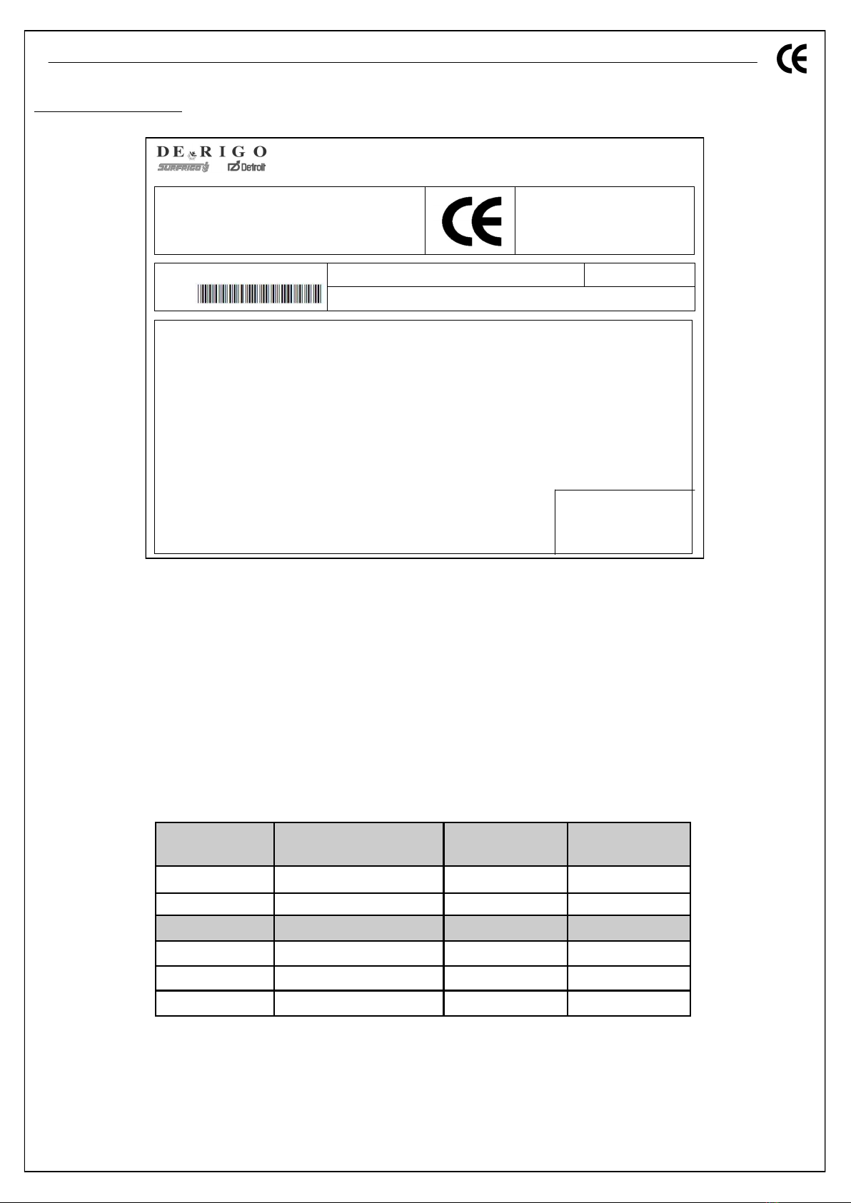
Serial number plate
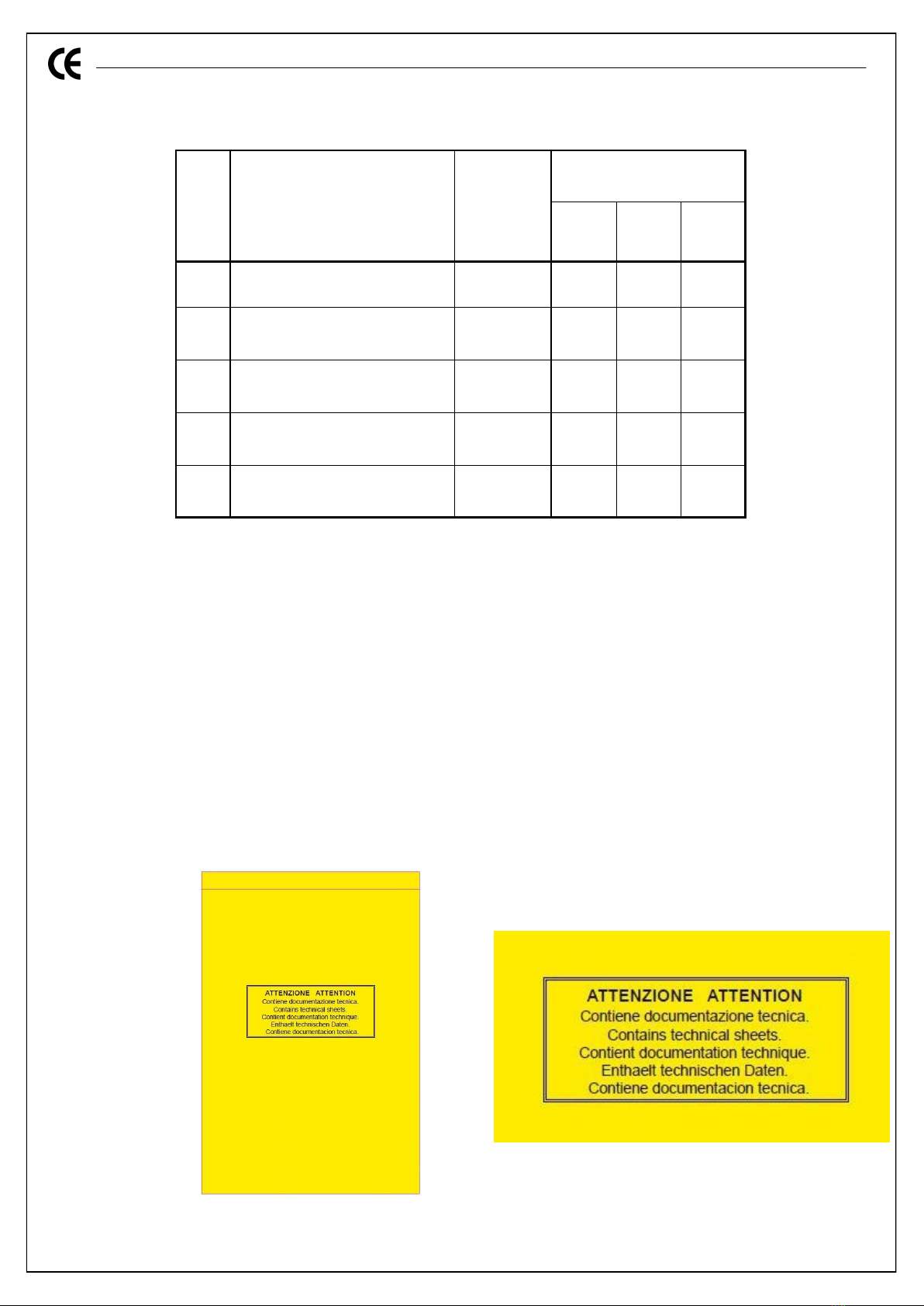
Environmental climate classes (ISO 23953-2)
Climate class Dry bulb temp. Relative humidity Dew point
1 16°C 80% 12°C
2 22°C 65% 15°C
3* 25°C 60% 17°C
4 30°C 55% 20°C
5 40°C 40% 24°C
6 27°C 70% 21°C
* With reference to environmental climate classes, it must be specified that when climate class 3 is
indicated, it means that climate class 3 or lower can be valid.
Model
Item
Via G. Buzzatti, 10
32036 Sedico –BL –Italy
Serial number
Series
Year
Voltage 1
Rated power 2Rated Current 8
MAX defrost power 3Anti-cond. res. power 9
MAX light bulb power 4
Climate class 5Temperature Class 10
Refrigerant fluid 6
Expanding Insulation
Fluid Compressor 7
1. Voltage 6. Refrigerant fluid/Refrig. fluid mass (Plug-in)
2. Rated power 7. Compressor model (if present)
3. Maximum defrost power 8. Standard absorbed current
4. Maximum light bulb power (if present) 9. Anti-condensation resistances power (if present)
5. Climate class (see table) 10. Temperature Class (ISO 23953-2)

6
De Rigo Refrigeration s.r.l.
IMPORTANT INSULATION CONDITIONS
Climate
The climate conditions of the environment where the counter is installed must be within the tempera-
ture range established by the counter class. To be within these parameters, it could be necessary to
install an air-conditioning system. The system should include an air humidity controller as excessive
humidity harms proper operation of the counter.
Dehumidifying the air with an air conditioner instead of with evaporators could be more economical as
the counters operate at lower temperatures and therefore absorb more electric energy at the same
cooling capacity efficiency.
Grouping several counters together in the same area could be advantageous operating-wise but could
be inconvenient for customers.
Air draughts
The counters must be positioned in such a way to limit or avoid air draughts which keep them from
operating properly. The counters must not be installed near doors or in areas exposed to strong air cur-
rents coming from ventilation or air conditioning vents, for example.
The design of the ventilation systems must take into account that there must be low air speed near
the counters, which in any case must never exceed 0.2 m/s.
Special attention must be paid to heating vents.
Thermal radiation and lighting
To limit the negative effects of radiant heat, make sure that the counters are not exposed to sunlight,
diffusers or air ducts, to uninsulated roofs or walls heated by sun or other heat sources. The penetra-
tion of radiant heat inside the counter increases operating costs and downgrades performance. Do not
point spotlights or other concentrated lighting devices towards the inside of the counters. External
fluorescent lighting is preferable to incandescent lighting and should be used.
Should incandescent lights be used, make sure that the lighting devices are appropriately ventilated by
large ventilation slots.
Surfaces at room temperature radiate enough heat to harm proper operation of the counter. This ef-
fect can be limited by installing heat-reflecting ceilings or placing the counters one in front of the
other.
Condensation
It is normal for absolute humidity to condensate on a cold surface if the air dew point is higher than
the temperature of the surface. Regardless of how a counter is insulated, condensation will be formed
if there is no ventilation around it. We therefore recommend leaving at least 60mm between the
counter and wall or any other object which can obstruct proper air circulation around the counter.
Transport and handling
The counter is shipped packed in a plastic sheet and fastened on two wooden boards which act as a
delivery support to facilitate handling. Keep the counter fully packed until it reaches the installation site
to prevent it from being damaged during transport. When the counter has been unpacked, do not dis-
pose of the packaging in common waste disposal centres, but contact specific waste collection facili-
ties for the recovery of materials and substances harmful for the environment.
The counter must be moved using a forklift truck, paying attention to the electrical devices and drains
underneath the counter.
Cleaning
The frequency at which display cabinets for vegetables, meat and other unpacked products must be
cleaned varies depending on the displayed product. Counters for preserving products such as meat,
dairy products and cold cuts must have the display surface cleaned at least once a week to prevent
the development and accumulation of bacteria.
The bottom of the tank must be washed frequently in cabinets subject to leakage of liquids or other
food products.
7
De Rigo Refrigeration s.r.l.
The frequency of cleaning however depends on how the counter is used and on hygienic require-
ments or other particular reasons. Blockage of the water drain can cause a failure which could possibly
damage other parts of the counter. Therefore qualified technical personnel should clean the drains pe-
riodically.
We recommend:
Wait for the counter temperature to come close to room temperature, empty the counter and clean it
without using abrasive products or solvents;
Daily cleaning with water and non-aggressive detergents of the outside zones surrounding the dis-
play area and the top parts of the shelves in contact with the product, paying special attention if meat
counters. Do not touch electric parts with a wet cloth;
Weekly, full cleaning of bottom shelves with water and non-aggressive detergents, lifting them with
the supplied hook and wearing the protective gloves foreseen by standards in force;
Full cleaning every three months of all parts of the counter, wearing the protective gloves foreseen
by standards in force;
Do not clean the appliance with water jets.
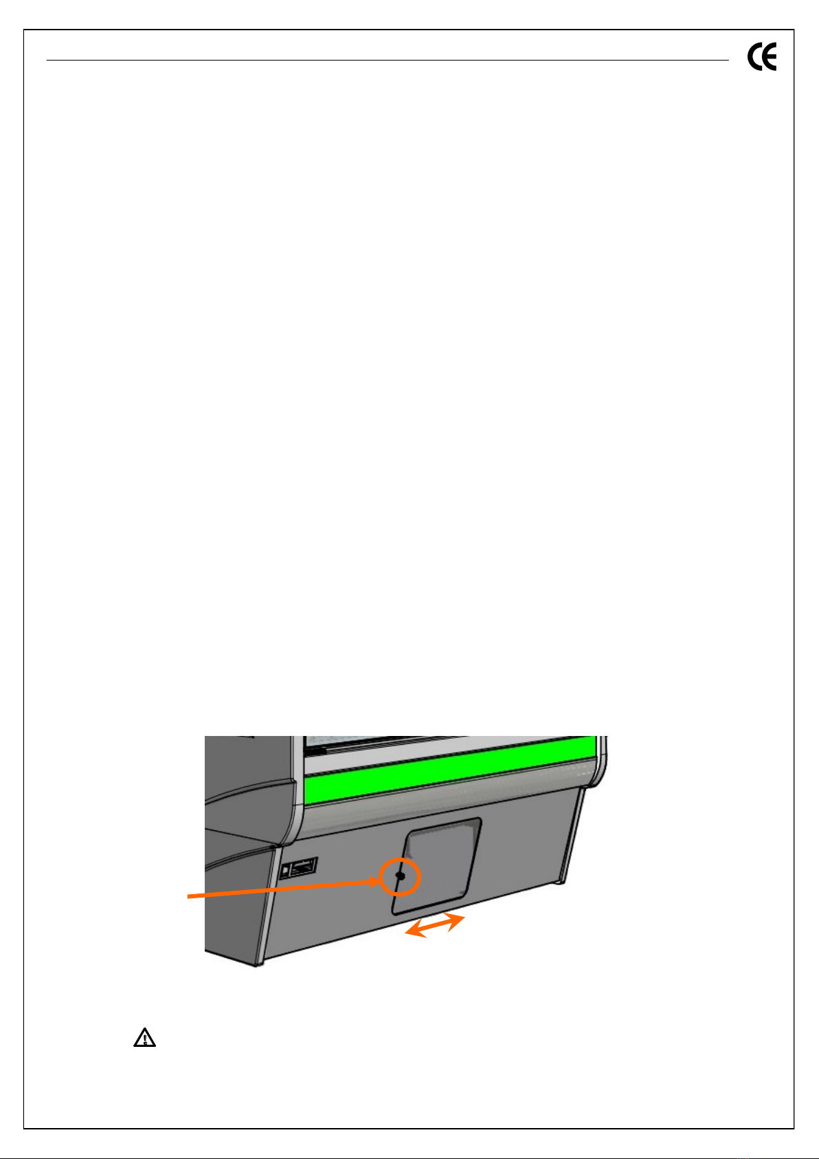
Cleaning the condenser
If present, the counter condensers gather dust and filth and must be cleaned regularly. In standard use
conditions, this operation must be done at least once a month using a hard bristle brush and a vacuum
cleaner. We recommend wearing gloves as the reduced thickness of the fins can cause cuts and abra-
sions. A dirty condenser reduces the counter's performance and increases energy consumption.
In detail: :
Periodically remove dust from in front of the frontal grate;
Switch-off the machine and disconnect the power supply cable before performing this operation;
Access the condenser by loosening the clamping screw of the frontal grate;
Slide the frontal protective grate to the right;
Clean the condenser with a jet of air or dry brush and eliminate, with vertical movements, the dust
and fluff deposited on the fins;
Slide the frontal grate to the left, fixing it with the previously removed screw and power the machine
again.
ATTENTION
During all maintenance and cleaning operations of the counter, use the specific personal protective
equipment, provided by the safety standards in force.
Clamping screw

8
De Rigo Refrigeration s.r.l.
WARNINGS
Installation recommendations
Qualified technical personnel must perform installation and maintenance of this appliance;
Correct positioning of the counter.
Check that the mains voltage corresponds to that provided on the identification plate.
This equipment may not be used in the open air and can not be exposed to rain.
Connect the appliance to an efficient earthing system.
Installation and the electrical connection must be performed in compliance with national and local
standards in force.
For the replacement of the cable and plug use only original factory spare parts.
Connect the power cable to a plug that is easily accessible even after the counter is positioned.
Isolate the power circuit upstream by means of an omnipolar circuit breaker switch with a minimum
contact opening of 3 mm.
ATTENTION: The arrangement and amount of products must not exceed the load limit. We also rec-
ommend making sure that the full load is not excessive for the structure of the counter. The following
are the approximate capacity values of the shelves. Respect these indications as much as possible.
N.B.: it is important that the full load of 350 Kg is not exceeded for a 1250 mm module.
> 60mm
Max capacity of bottom surface Max capacity of hanging shelf
100 Kg x Surface 625 90 Kg x Shelf 450

9
De Rigo Refrigeration s.r.l.
General recommendations
To be read before using the counter.
This manual forms an integral part of the product and must be stored with the equipment to facili-
tate rapid consultation.
The adjuster must not be used with other functions other than those described below, specifically it
can not be used as a safety device.
Before proceeding check the application limits.
Safety precautions.
Before connecting the counter ensure that the supply voltage is as required.
Do not expose the unit to water or humidity: use the counter only within the limits of operation pro-
vided for.
Attention: before carrying out any kind of maintenance remove electric connections from the
counter.
The electric panel must never be opened.
If malfunction or failure occurs, contact qualified staff for analysis and repair.

10
De Rigo Refrigeration s.r.l.
PRECAUTIONS FOR USE AND MINOR MAINTENANCE
Before starting any cleaning, maintenance or parts replacement, even if not electrical, make sure that
electric power is disconnected and/or open the omnipolar power isolator.
Any technical assistance and extraordinary maintenance must only be carried out by qualified technical
personnel.
ATTENTION: when the appliance is no longer working or usable, do not dispose of it in com-
mon waste disposal centres, but contact specific waste collection facilities for the recovery of
materials and substances harmful for the environment.
Loading products for display
Height of Load
Food products preserved within the load limit are appropriately refrigerated. Those preserved beyond
the load limit cannot be appropriately refrigerated and impair the circulation of air, thus jeopardising
operation of the counter and deterioration of all the food products. Also remember that products must
not cover the air inlet for the counter to operate properly.
A refrigerated display counter is not intended to chill perishable food products but rather to keep them
at the temperature at which they were introduced. Food products warmer than that specified for the
counter should not be placed in a refrigerated counter.
Do not leave refrigerated food products on pallets or similar structures inside the shop longer than that
strictly necessary for transport and loading.
Do not overload the counter: this is the most common error which can cause secondary defects, such
as the anomalous formation of frost thus blocking the evaporator and even causing the complete stop-
page of the counter. The even distribution of the goods without leaving empty spots guarantees the
best operation of the counter. It is good practice to rotate the stock when loading the counters with
new products. The older products must be the ones closest to the customers so they are sold first.
N.B.: Counter operation is guaranteed in the climate conditions indicated on the serial number plate
and according to standards ISO 23953-2 if loaded evenly and not beyond the conforming loading line
on each counter.
11
De Rigo Refrigeration s.r.l.
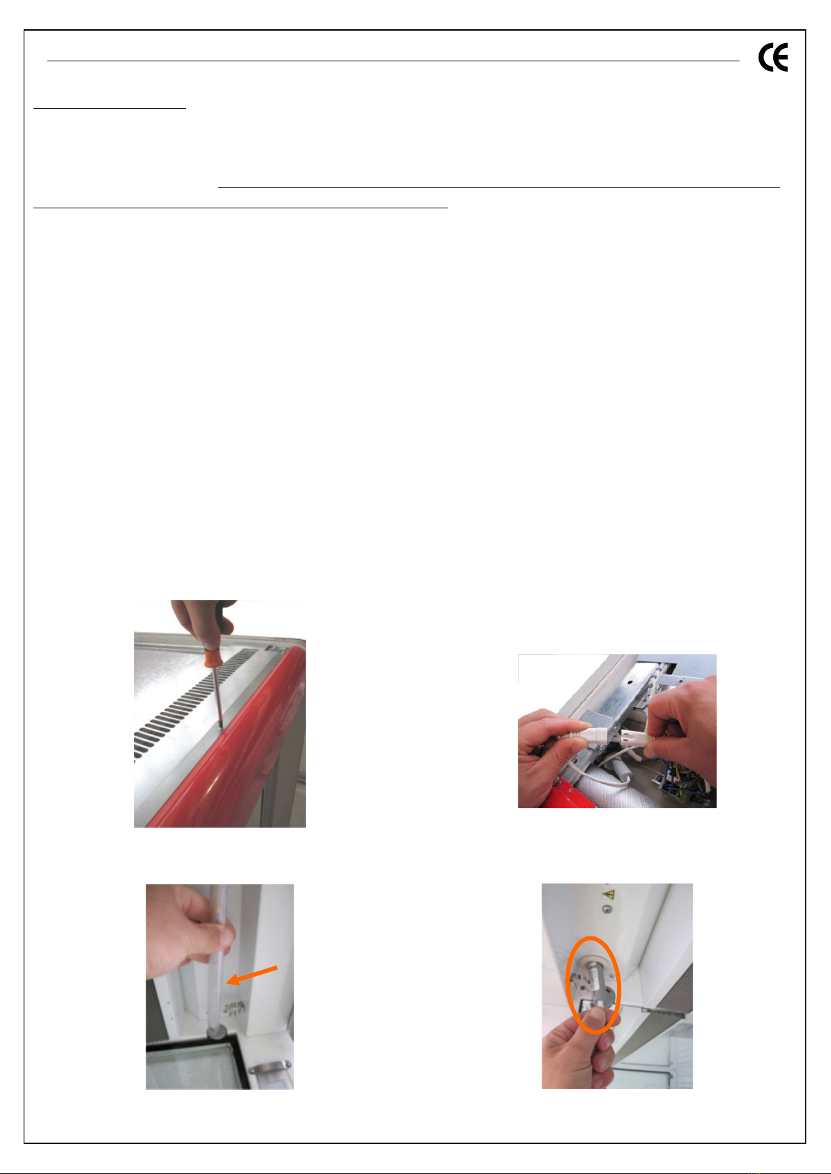
Replacing light bulbs
Replacing roof LED light bulb
Before starting any operation entailing light bulb replacement, make sure power is disconnected and/or
open the power isolator. Also remember that any technical assistance and extraordinary maintenance
must only be carried out by qualified technical personnel.
IMPORTANT: replace the light bulb with a part of the same type and power.
To replace the light bulb:
1. Disconnect power to the counter (disconnect the power supply cable);
2. Remove the screws fixing the covering sheet metal on the counter's roof Fig. 2a;
3. Disconnect the power plug of the light bulb to be replaced Fig. 2b;
4. Release the light bulb from the fastening springs by slightly pressing downwards on the counter
and extracting the power supply cable from the hole Fig. 2c;
5. Insert the power supply cable of the new light bulb in the hole, making sure not to remove the
protection. Restore the light bulb in its own seat Fig. 2d;
6. Connect the power supply cable of the just-installed new light bulb;
7. Fasten the covering sheet metal on the counter's roof;
8. Power the counter again (reconnect the power supply cable).
Fig. 2a
Fig. 2b
Fig. 2c Fig. 2d

12
De Rigo Refrigeration s.r.l.
Replacing light bulbs
Replacing roof LED light bulb
Before starting any operation entailing light bulb replacement, make sure power is disconnected and/or
open the power isolator. Also remember that any technical assistance and extraordinary maintenance
must only be carried out by qualified technical personnel.
IMPORTANT: replace the light bulb with a part of the same type and power.
To replace the light bulb:
1. Disconnect power to the counter (disconnect the power supply cable);
2. Remove the screws fixing the covering sheet metal on the counter's roof Fig. 2a;
3. Disconnect the power plug of the light bulb to be replaced Fig. 2b;
4. Release the light bulb from the fastening springs by slightly pressing downwards on the counter
and extracting the power supply cable from the hole Fig. 2c;
5. Insert the power supply cable of the new light bulb in the hole, making sure not to remove the
protection. Restore the light bulb in its own seat Fig. 2d;
6. Connect the power supply cable of the just-installed new light bulb;
7. Fasten the covering sheet metal on the counter's roof;
8. Power the counter again (reconnect the power supply cable).
Fig. 3a Fig. 3b
Fig. 3d
Fig. 3c

13
De Rigo Refrigeration s.r.l.
Positioning display shelves
Apply the price tag profile on the shelves proceeding as follows:
1. Insert the price tag spacers in the specific housings Fig. 5a;
2. Turn the price tag spacers 90° until they lock;
3. Insert the aluminium profile along the entire length of the shelf Fig. 5b;
4. Insert the price tag profile along the entire length of the previously positioned aluminium profile
Fig. 5c.
Apply the shelf supports and shelves only after having installed the price tag profile, keeping in mind
that the shelves can also be positioned horizontally (Fig. 6a) or with a –10° inclination (Fig. 6b).
Fig. 5a Fig. 5b Fig. 5c
A
Fig. 6a
B
Fig. 6b
A B

14
De Rigo Refrigeration s.r.l.
ELECTRIC COMPONENTS
Lighting
For that which regards counter lighting, remember to switch the lights off as soon as possible to save
energy.
Furthermore the counters are equipped with electronic reactors which, if operating conditions are not
appropriate, can trip switching off the lights connected to them. To restore correct functioning, just
switch the counter off and back on.
Electric panels
The following are the different types of electric controllers belonging to the panels with which the
counter can be configured. Also remember that the product will only have one of the available configu-
rations.
ATTENTION:
For further information on the chosen instrument, consult the specific manual of the de-
vice supplied together with the counter (see pag. 16). Also pay close attention to consult the technical
sheet of the controller actually installed on your counter.
15
De Rigo Refrigeration s.r.l.
Electric panels
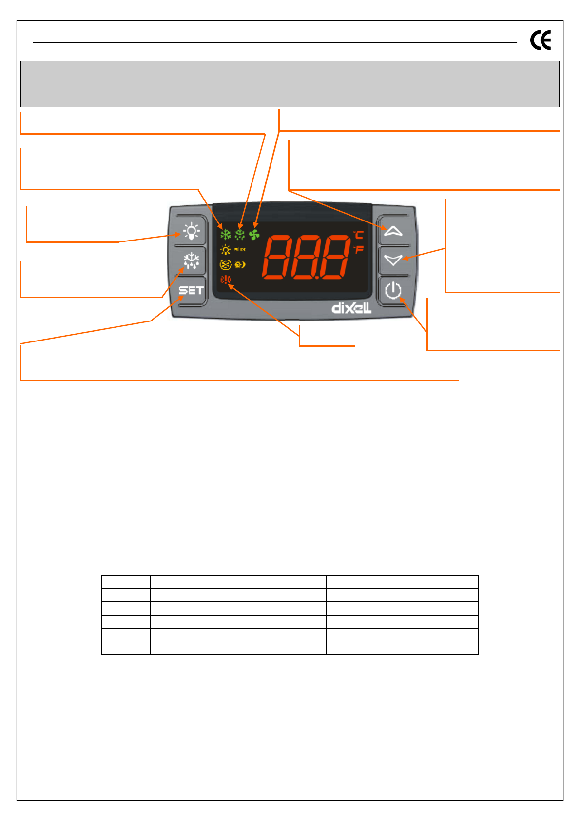
DIXELL XR40CX / XR50CX
Locking the keypad
Press èand à simultaneously for 2 seconds to lock the keypad; the flashing text “POF” appears; repeating the
procedure unlocks the keypad and displays the flashing text “PON”.
View the setpoint value
If you press "set" and release it, the value will be view-only, without any possibility of editing it. Pressing it again
and waiting 5 seconds, it returns to the probe temperature reading.
Edit the setpoint value
Press the "set" key for approximately 3s until the unit of measurement icons flash. Then release the key and set
the new value by pressing èand à. When finished, press the "set" key once to memorise the value.
Manual activation of defrost cycle
The defrost cycle can be activated manually by keeping the “defrost” key pressed for more than 3 seconds. If
defrosting starts, the LED g switches on fixed. If nothing happens after this time, it means the temperature
detected by the defrost end probe is higher than the value set in parameter dTE (see adjustment parameters
table).
Exiting alarm
Once detected, the alarm signal remains displayed until the alarm condition finishes.
How to reset alarms
Probe alarms P1 and P2 trigger approximately 10 seconds after the probe failure; they are reset automatically 10
seconds after the probe resumes proper operation. We recommend checking the connections before replacing
the probe.
Temperature alarms HA and LA are reset automatically as soon as the thermostat temperature returns to nor-
mal, when defrost starts or the door opens.
The external alarm EA is reset as soon as the digital input is deactivated.
Pressing the key for 3s toggles
the instrument from ON to OFF
and vice versa.
ON Defrost active, flashing dripping presence.
To see and modify the SET point; in programming, allows to select the parameters and confirm an operation. Pressed for
3s, when the MIN and MAX temperatures are viewed, allows to reset the record.
ON Alarm
Scrolls menu options, de-
creases values. Pressed for
3s activates the sections
menu. Pressing it briefly
allows you to enter the quick
access menu.
Keeping the key pressed for 3s acti-
vates manual defrost.
Scrolls menu options, increases values. Pressed for 3s activates the sec-
tions menu.
Pressing it briefly allows you to enter the quick access menu.
ON compressor and valve adjustment active,
flashing compressor anti-short cycle.
Switches the light on
or off
ON fan is active, flashing door open or delay after defrost.
Mes. Cause Status of outputs
P1 Probe 1 error Output according to CON e COF
P2 Probe 2 error End of timed defrost
HA High temperature alarm Not modifiable
LA Low temperature alarm Not modifiable
EA External Alarm Not modifiable
Local alarms
16
De Rigo Refrigeration s.r.l.
TECHNICAL INFORMATION: main adjustment parameters.
TECHNICAL DOCUMENTATION INSERTED IN COUNTER
Each counter has a yellow envelope placed inside near the serial number plate. This envelope contains
all the required technical documentation, such as:
- Use and maintenance manual;
- Declaration of conformity;
- Quality control sheet;
- Test inspection certificate;
- Counter wiring diagram;
- Reactor board diagram (only if foreseen);
- Manual of controller installed on electric panel (only if foreseen);
- Controller parameters map (only if present);
- Various documentation such as: motorised night blind instructions, electronic valve instructions,...
(only if present).
N.B.: At times, labels with additional instructions and/or recommendations are applied on some counter
surfaces.
Par. DESCRIPTION Adjustment
range
SAPPHIRE
Cl. H
(+1/+10°C) Cl. M2
(+5/+8°C) Cl. M1
(-1/+5°C)
SET Temperature control setting LS÷US 2.0 0.0 -2.0
HY Differential 0,1÷25,5 4.0 4.0 4.0
dtE End defrost temp. -50,0÷50,0 °C 8.0 8.0 8.0
idF Defrost cycles interval 1÷120 hours 12.0 12.0 12.0
MdF Maximum defrost duration 0÷255 min 50.0 50.0 50.0

17
De Rigo Refrigeration s.r.l.
TECHNICAL DATA
Climate class T 1250 1875 2500
Voltage V 220÷230
Frequency Hz 50
Operating temperature °C 0/+2
Max absorbed nominal power W 500 704 1046
Max absorbed nominal current A 3.65 5.39 7.50
Max absorbed defrost power W 34 76 114
Climate class ISO 23953-2 M1
SAPPHIRE M1
Climate class T 1250 1875 2500
Voltage V 220÷230
Frequency Hz 50
Operating temperature °C +3/+5
Max absorbed nominal power W 500 704 1046
Max absorbed nominal current A 3.65 5.39 7.50
Max absorbed defrost power W 34 76 114
Climate class ISO 23953-2 M2
SAPPHIRE M2
Climate class T 1250 1875 2500
Voltage V 220÷230
Frequency Hz 50
Operating temperature °C +6/+8
Max absorbed nominal power W 500 704 1046
Max absorbed nominal current A 3.65 5.39 7.50
Max absorbed defrost power W 34 76 114
Climate class ISO 23953-2 H
SAPPHIRE H
18
De Rigo Refrigeration s.r.l.
EMERGENCY SITUATIONS
1. The counter does not start or switches off.
Check whether there is an electrical blackout in progress;
Check that the main wall switch is on.
If the electrical interruption does not depend on the above-mentioned reasons, immediately contact
the closest service centre and fully empty the counter, placing the removed products in cold rooms or
in other equipment capable of preserving them.
2. The counter temperature is too low.
Check that the counter is not loaded beyond the recommended level and that the air vents are
not obstructed;
Start a forced defrost and clean the counter (following safety measures) to then resume standard
operation;
Make sure that the counter is not near heat sources and/or air draughts which could hinder
proper operation;
Should malfunctioning persist, immediately contact the closest service centre.
3. The counter makes too much noise.
Check that the screws and nuts are fastened all the way.
Using a level, check that the counter is level.
Should the noise persist, immediately contact the closest service centre.
4. Gas Leak or Fire.
The refrigerant circuit must not be damaged to prevent leaks into the environment. If the gas comes
into contact with the air, there is a risk of fire in the presence of a suitable trigger such as an open
flame or sparks caused by electrical equipment.
For this reason components have been adapted to prevent these risks and when they need to be re-
placed, original components which have been approved for the specific use must be requested.
If servicing due to a breakdown or malfunction, qualified personnel must always be contacted to as-
sess and perform the type of procedure required in compliance with statutory safety regulations for
this type of gas.
The equipment needed for the procedures must comply with the same requirements as the compo-
nents of the system, thus avoiding electrical equipment and flames in the presence of flammable
gases.
For specific procedures related to emptying and loading the system, proceed with equipment suitable
for
the type of gas (vacuum pump, leak detector, etc.) and in any case avoid the presence of flammables
in the premises and in particular contact with flames or sparks.
5. Other particular situations.
Metal parts must be handled with care to avoid possible and not unlikely abrasions and/or cuts as
well as possible crushing.
Removing the bottom surfaces exposes the evaporator and motor fans with the ensuing danger
that this could cause.


DE RIGO REFRIGERATION srl
Registered and Administrative Office
Via G. Buzzatti, 10
32036 Sedico –BL –Italy
Tel. +39 0437 5591 Fax +39 0437 559300
info@derigorefrigeration.com
Ronchi dei Legionari Plant
Via Redipuglia, 163
34077 Ronchi dei Legionari –GO –Italy
Tel. +39 0481 477411
Fax +39 0481 776330
The company reserves the right to make technical changes without prior warning.
This manual suits for next models
2
Table of contents


