De Soto Airflow User manual
*AIRFLOW DE SOTO
(CODE SE)
BODY SERVICE MA NU AL
• FOREWOR D •
Many new and revolutionary principles of design , which heretofore
have never been applied to the manufacture of automobile bodies , are
encompassed in the new Airflow body.
These improvements are such that they reduce body service to a
minimum by increasing the natural rigidity of the all-steel unit to a
point far beyond that considered possible in the past. ·At the same
time , should body repairs become necessary due to collision or other
abnormal causes, the ease with which such damage may be repaired
has been greatly increased .
As an example, whole body sections fractured beyond the point
where they may be economically repaired, may be cut out with a torch
and a complete new section welded in its place, not affecting any other
part of the body structure and restoring the all-steel unit to its original
state of incomparable rigidity . Small punctures in any part of the
body metal may likewise be repaired by merely cuttin g out the metal
around the fracture and welding a small piece of sheet steel in its place.
As a result of these fundamental advancements in constru ction , the
methods employed in servicing Airflow bodies will differ in a great
many respects from those with which the averag e body mecha nic is
familiar .
It is th e purpos e of this Body Service Man ual to cover in as much
detail as possible the servicing of each indiv idua l part of the Airflow
Body, starting with maintenance items such as lubr ication and tight -
ening, and progressing to major body repai rs invol ving the straighten-
ing and replacing of body braces and pillars.
The procedures described in this Body Service Manual for the serv -
icin g of Airflow bodies are not presented in elementary form and are
not int ended to constitute a textbook for t hose who have not had
previo us experience in this class of work. It will, however, prove to be
a valuabl e guide when servicing bodies of the Airflow type and, con-
sequently, should be carefully studie d by all those engaged in work of
this nature . •
DE SOTO MOTOR CORPORATION
Division of Chrysle r Corporation
DETROIT, MICHIGAN
PR ICE 50C N ET
PRINTED I N U. S. A .
OE SO T O MOT O R CORPORAT ION
DI V IS ION OF CHR Y SLE R CORPOR AT ION
2. 3
24 2·s 26
6
2 28 29 30 3·1
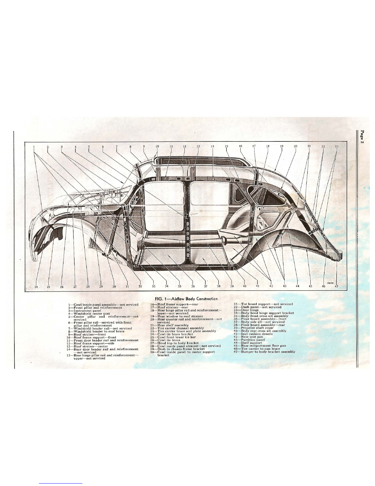
I- Cowl inside panel ass e mbly - not ser viced
2-Front pillar and reinfo rcement
3- Instrument panel
4-Windshield center post
5- Center pillar and reinforc e meat - not
serviced
6- Fr ont pillar rail - serviced with front
pillar and reinforcemen t
7-Windshield header rail-not serviced
8- W indsh ield header to roof brace
9- Roof strainer-front
10- Roof fram e support - front
I I-Front do or header rail and reinforcem e nt
12-Roof fram e support -side
13- Roof strain er-center
14___:.Re ar door header rail and reinforcement
-not serviced
15-Rear hinge pillar rail and reinforcemen t-
upper - not serviced
3·2
10 11 12 13 14
3·3 34 3·5 36 37 38
FIG. 1-Airflow Body Constructicn
16- Roof frame support - rea r
17-Roof strainer - rear
18-Rear hinge pillar rail and reinforcement-
lower - not serviced
19- Rear window to roof strainer
20-R ear quarter rail and reinforcement - net
serviced
21- Rear shelf assembly
22-Tire car rier channel assembly
23-Tire carrier brace and plate assembly
24- Cowl tie brace bracket
25- Cowl front lower ti e bar
26- Cowl tie brace
27-Hood top to body bracket
28-Cowl inside panel strainer - not serviced
29- D ash to chassis frame brack et
30 - Cowl inside pan el to motor support
bracket
15
39
17 18 20
· 40 41 42 43
31-Toe board support-not serviced
32- Dash panel-not ser vice d
33-Door hinge
34-Body hood hing e support bracket
3S~Body front cross sill assembly
36-Floor board assemb ly - front
37- Body side sill - not .serviced
38-Floor board assemb ly - rea r
39-Pr opeller shaf t cover
40-Body rear cross sill ass emtly
41- Seat cushion dowels
42- Rear seat pan
43-Partition panel
44-Shelf support
45-Rear cumpartment floor pan
46-Tire carrier to pan brace
47-Bumper to bo dy bracket ass embly
44
21
4·5 46 4·7
;;,u
~
N
AIRFLOW BODY SERVICE
MANUAL
CONSTRUCTION
The Airflow body is of all-steel unit construction,
fabricated from steel panels and pressed steel
rails, channels and braces welded and riveted into
one solid, rigid structure of incomparable strength
and durability. Beyond this one fundamental
similarity to other all-steel body designs the
construction of the Airflow body differs in practi-
cally every respect from anything heretofore
applied to automobile body design.
Were it possible to remove the outer shell, the
braces , channels and rails, some of which are
int egral with the outer panels, would appear as
illustrated in Fig. 1. As will be seen by referring
to this phan tom view, the Airflow body requires
no chassis fram e for rigidity but the body struc -
tur e is augmented by an additional lower body
frame, upon which the various parts of the chassis
are mounted, bolted with from 22 to 40 body bolts
to the lower contour of the body itself.
A rail extends from the extreme rear corners of
the body up each side of the sloping rear quarters
and along the inside of the roof panel to join box -
like steel body door hinge pillars above the corners
of the windshields. By placing an inverted pressed
steel channel or reinforcement in the corners of
th e sloping windshi eld stanchions a rigid brace is
provided which ties the top of the body door hinge
pillar to a solid steel flanged plate, constituting
the cowl inner panel.
This plate is welded in one solid piece from the
line of the base of the windshield, the full depth of
the engin e compartment, forward to the front
bumper bracket. Vertical and lateral members,
also of pressed steel, tie the entire assembly
together , with the lower box -like body rails into
a most rigid, dur ab le and serviceable unit.
It is quit e appa rent from the foregoing brief
description of th e construction of an Airflow
body that th e metho ds to be employed for servicing
it will differ in a gre at many respects from those
employed on other all -stee l bodies.
These bodi es are built to withstand tremendous
strains and stresse s without requiring any atten-
tion, therefore the necessity for service has been
reduced to a mini mum . Should servicing become
imperative due t o collision or other abnormal
causes, how ever, the Airflow body is so designed .
that it may be repaired an d restored to its original
state of rigidity and durability with comparatively
litt le lab or expens e. This feature has been ob -
tained as mentioned in the "Foreword " to this
manual by so constructing the body that whole
or partial body sections may be cut out with a
torch and a new section welded in as a unit, or
plates of sheet metal of approxim ately the same
thickness as the original panel may be cut out of
sheet steel, formed to follow the contour of the
body shell and welded into place after cutting
out the damaged piece .
INSPECTION
Any automobile body, regardless of its natural
rigidity, must be periodically inspected for settling.
This is particularly important during the first
thousand miles of service of a new car. The follow-
ing points should be carefully checked and adjusted
for maximum body service and quiet operation :
1. Check all body bolts to be sure they are tight.
2. Check floor-board screws and tighten if
necessary.
3. Inspect all door hinges, locks, window
regulators and remote controls and tighten.
4. Ch eck door lock striker plates and adjust.
5. Check all window glass for side play and
metal contact with garnish mouldings and
reveals. Eliminate side play by shimming
runs with card board and eliminate metal
contacts by moving glass roller or weather-
strip.
6. Road test car and enumerate points requiring
adjustment. Refer to proper section of this
Body Service Manual for suggestions on
method of making any nec essary corrections.
LUBRICATION
Door hinge pins should be lubricated with a
drop or two of light machine oil periodically, to
insure quiet and smooth operation and also to
prevent the hinge pins and hinges from galling at
the bearing surfaces, resulting in excessive clear-
ances at these points and causing objectionable
door ratt les which can only be completely elimin-
ated by replacement of parts . Excess oil on the
outside of the hinge should be removed im-
mediately, to prevent dust from collecting and
damaging the lacquer finish.
Door latches may be lubricated with a light
application of vaseline or similar lubricant. Soap
may be applied to all points of friction, with
marked success .
Do not apply oil or grease of any kind to rubber
weatherstrips, anti-rattl e buttons, etc . Castor oil
is not only an exceptional lubricant but also a
rubber preservative and should be employed at
all such points.

Page 4 A-, RF L O W BO D Y SERV I CE M A N U A L
FIG. 2-Accessibility to Side of Engine
1- Front wheelhouse panel clinch nuts
2-F ront wheelhouse panel
Window regulator, door ventilator regulator
and door latch shafts should be sparingly lubri -
cated as frequently as possible, or wh eneve r it
becomes necessary to remove the door trim panels
for any reason.
Leather-bound weathercord, around the door
fram es, may be lubricated to prcve~t possib~e
squeaks from developing by making a hght apph-
catiori of tan paste shoe polish to the leath er,
wiping off the excess polish with a clean cloth.
One application of this nature should suffice for
at least six months .
TIGHTENING
Annoying rattles, difficult to locate, might de-
velop around the floor-boards, door hinges and
body to assembly member bolts unless these are
periodically ti ghtened. .
It is advisable to give preferred attention to
these bolts arid scr ews during the first 1000 mil es
of operation of a new car, t ight ening th em as fre-
quently as possible during t he breaking -in peri od.
ALIGNMENT
The Airflow body being rigid m construction,
and its component parts having been weld ed
together in a stat e of alignment, is therefore in
correct alignment whe n manufactured, and will
remain so unless subject ed to a severe blow or
twistin g strain, such as might be experienced in
an accident. Any condition of misali gnment which
may develop will, in a majority of instanc es, be
only visual in the body, or appar ent on the road
by th e front an d rear wheels not following in the
sam e track. This can result from a brok en spring,
bent axle or spr ing hanger, and can be corrected
by straigh te ning or replacing th e affected part.
Misalignm ent of the body itself can be isolated
by comparin g diagonal dimensions tak en from the
int erio r of th e car body at different heights and
differe nt angles.
For example, the distance from a point on the
front of th e left body door hing e pillar to a point
on the right rear body hinge pilla r should be exactly
equal to the distance from the corresponding point
on the right front body hinge pillar to the cor-
responding point on the left rear body hinge pillar.
Similar measu rem ents ma y be ·taken from other
angles where the misalignment is suspected to
exist on some other plan e.
Once located, it is only neces sary to st raighten
the bent or sprung brac e or cross member. In
extreme -cases, it may be necessary to remov e the
affected-cross bracing , align the body , straighten
the brace and gas weld it back in place, or replace
the entire part. This will depend upon the nature
of the damage which must be repai red .
The Airflow body cannot be sprung or twisted
by placing shims under body bolts. Such practice
might result in seriously distorting the lower body
frame side members subjecting them to unwonted
strains and stresses.
ACCESSIBILITY
The Airflow body and chassis are designed to
afford the utmost in acc essibility from a service
standpoint.
As an example of the consideration given to
this most importan t service problem refer to Fig. 2
illustrating the manner in which the side of the
engine is exposed for adjustments or replacements.
To obtain ready access to the sides of the engine
it is only necessary to remove one front wheel, the
front wheelhouse panel studs fron.1.the clinch nuts
(1, Fi g. 2) and the wheelhouse panel (2).
By permitting the mechanic to work in the
position illustrated, th e necessity of removing
the manifo ld is obviated when grinding valves ,
et c., and either side of the engine may be clearly
exposed for making the most exacting inspections
and adjustments.
FIG. 3- BatteryInspection
1- Front seat cushion support 4- Ba tte ry cable terminal (negativ e)
2- Battery cover lid 5- B attery filler cap
3- Battery cover lid thu mb screw 6- Battery cover assem bly
A I R FL O W BO D Y S ERV I C E M-A t\( U A L Page 5
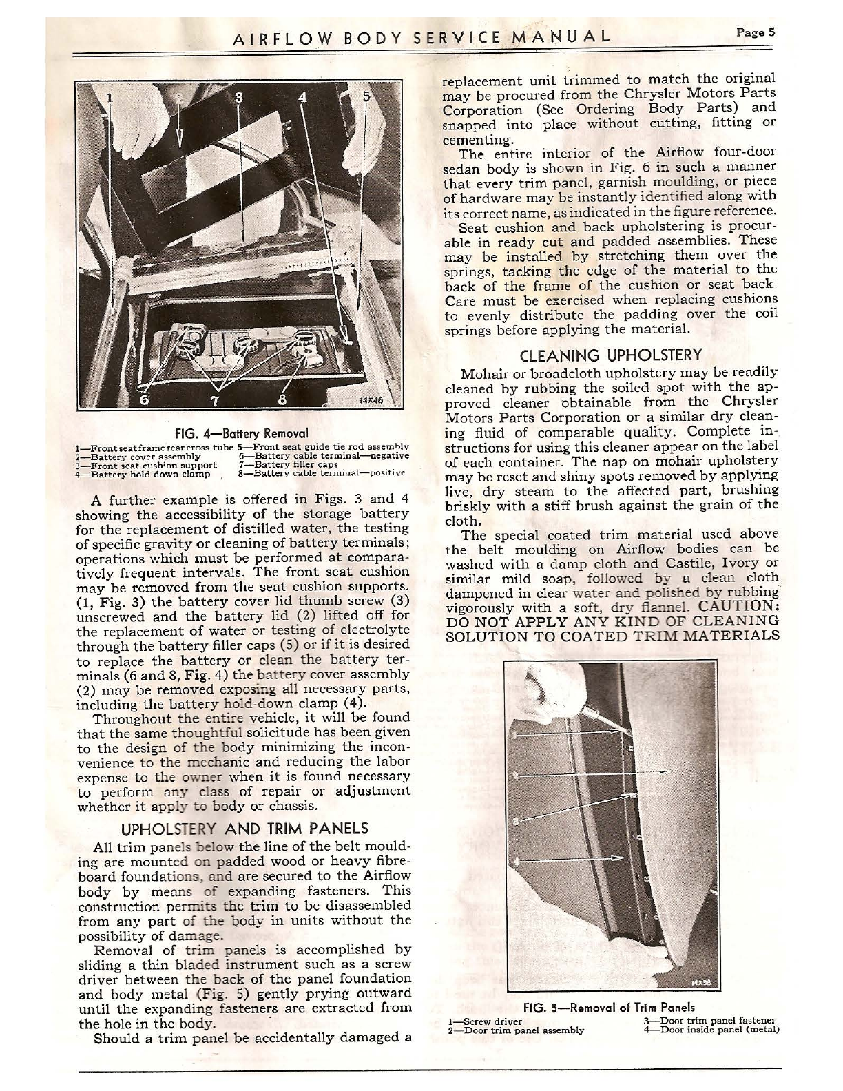
FIG.4-Battery Removal
1- Fronts eatframerearcross tube 5-Front seat guide tie rod assemhlv
2- Battery cover assembly 6-Battery cable terminal-negative
3-Front seat cushion support 7-Battery filler caps
4-Battery hold down clamp . 8-Battery cable terminal-positive
A further example is offered in Figs. 3 and 4
showing the accessibility of the storage battery
for the replacement of distilled water, the testing
of specific gravity or cleaning of battery terminals·
operations which must be performed at compara~
tively frequent intervals. The front seat cushion
may be removed from the seat cushion supports.
(1, Fig . 3) the battery cover lid thumb screw (3)
unscrewed and the battery lid (2) lifted off for
the replacement of water or testing of electrolyte
through the battery filler caps (5) or if it is desired
to replace the battery or clean the battery ter-
minals (6 and 8, Fig. 4) the ba tt ery cover assembly
(2) may be removed expos ing all necessary parts
including the battery hold-down clamp (4). '
Throughout the enti re vehicle, it will be found
that the same though t ful solicitude has been given
to the design of the body minimizing the incon-
venience to the mechanic and reducing the labor
expense to th e owner when it is found necessary
to perform an y cla ss of repair or adjustment
whether it ap ply to body or chassis.
UPHOLSTERYAND TRIM PANELS
All trim pane ls bel ow the line of the belt mould-
ing are mount ed on padded wood or heavy fibre -
board foundati ons , and are secured to the Airflow
body by mean s of expanding fasteners. This
construction per mits the trim to be disassembled
from any part of the body in units without the
possibility of da mag e.
Removal of t rim panels is accomplished by
sliding a thin blade d instrument such as a screw
driver between the back of the panel foundation
and body metal (Fig. 5) gently prying outward
until the expanding fasteners are extracted from
the hole in the body.
Should a trim panel be accidentally damaged a
replacement unit trimmed to match the original
may be procured from the Chrysler Motors Parts
Corporation (See ·Ordering Body Parts) and
snapped into place without cutting , fitting or
cementing.
The entire interior of the Airflow four-door
sedan body is shown in Fig. 6 in such a manner
that every trim panel, garnish moulding, or piece
of hardware may be instantly ident ified along with
its correct name, as indicated in the figure reference.
Seat cushion and back upholstering is procur-
able in ready cut and padded assemblies. These
may be installed by stretching them over the
springs, tacking the edge of the material to the
back of the frame of the cushion or seat back.
Care must be exercised when replacing cushions
to evenly distribute the padding over the coil
springs before applying the material.
CLEANING UPHOLSTERY
Mohair or broadcloth upholstery may be readily
cleaned by rubbing the soiled spot with the ap-
proved cleaner obtainable from the Chrysler
Motors Parts Corporation or a similar dry clean-
ing fluid of comparable quality. Complete in-
structions for using this cleaner appear on the label
of each container. The nap on mohair upholstery
~ay be reset and shiny spots removed by applying
hve, dry steam to the affected part, brushing
briskly with a stiff brush against the grain of the
cloth.
The special coated trim material used above
the belt moulding on Airflow bodies can be
washed with a damp cloth and Castile, Ivory or
similar mild soap, followed by a clean cloth
dampened in clear wate r and pol ished by rubbing
vigorously with a soft, dry flan nel. CAUTION:
DO NOT APPLY ANY KIND OF CLEANING
SOLUTION TO COATED TRI M MATERIALS
FIG.5-Removal of Trim Panels
1-Screw driver 3-Door trim panel fastener
2- Door trim panel assembly 4-Door inside panel (metal)

Pag-~ 6 A I RFL O W e:o~D Y SERV l~CE M A N U A L
I- Windshield regulator handle
2- W indshield garnish moulding
3-Front door hinge pillar trim paud
4-- Ventilating window adjusting handle
5- Windshi eld header trim panel
6- Fr ont door garnish moulding
?- Headlining front garnish moulding
8...---Front door opening garnish moulding
9- Center pillar garnish mou lding
· FIG. 6-Body Interior, Trim Panels and Hardware
14-Headlining center trim panel
IS-Rear door opening garnish moulding
16 -~ Uppcr quarter trim panel
28-Remote control handle
29-Front door trim panel
17-Upp er quarter garnish moulding
18- Door header dovetail-upper
30-Front seat cushion 9.ssembly
31-Center pillar lower trim panel
32-Front seat back assembly
19- H ead lining rear garnish moulding 33-Front door weathercord assembly
34- Front door lock striker
20-Rear seat back assembly 35- Front seat frame
21-Over rear window trim pan el 36-R ea r door lower wedge
22- Rear window garnish moul ding 37-R ear seat ba ck frame sector
38-Rea r seat cushion as sembly
39-Rea r side arm rest support assembly
40-Rear side arm rest cover assembly
I0- Do me light switch 23- Luggage compartment light
24-Rear window glass
I I- Center pillar trim pan el- upper
12-Door bod y header tr im panel
13- Headlining side garnish mou lding 25-Luggage compartment
26-Cowl trim panel
27-Glo ve compartment door
SIN CE COMPLETE DETERIORATION WILL
RESULT. USE ONLY CASTILE, IVORY OR
SIM ILAR SOAP.
The instructions for cleaning coated trim
materi als also apply to the cleaning of leather or
imitat ion leather. Under no circumstances must
a clean ing fluid be used on materials of this nature.
POLISHES,CLEANERSAND
SEALING COMPOUNDS
APP ROVED LIQUID POLISH has been de-
·.-eloped by factory engineers and may be used to
::-esto re the lustre without harming the finish. To
o:>:ain the best results this polish should be
a?pli ed about every two weeks. Use of this polish -
is recommended when frequent polishing can ·be
done. This must not be used on a surface which
has been previously waxed, unless the wax has
been removed with paste cleaner . Otherwise a
gummy surface will result.
APPROVED POLISHING WAX may be ap-
plied, after the surface has been thoroughly
cleaned, with Approved Paste Cleaner, to protect
the finish. This wax must not be applied over
chalked surfaces or over liquid polished surfaces.
Liquid polish or Saxon Glaze are recommended
because of the ease of application. However; for
those who desire a waxed surface, this ·wax is
recommended. Extreme care must be used to
apply <:>nlya very thin coating of wax . The thinner

AIRFLOW BODY SERVICE MANUAL Page 7
th e wax coat the better will be the finish . A thick
coating of wax, caused by heavy applications or
rep eated thin coats, should be avoided. Best re-
sults will be obtained by cleaning the surface with
paste cleaner before applying wax at any time.
APPROVED SAXON GLAZE which produces
a wax -like finish, is in liquid form and can be applied
to a new car in much less time than wax. It pro-
duces a very hard, mirror finish which lasts con -
siderably longer than wax. It is especially service -
able on the sea coast where salt air and fog prevail.
Saxon Glaze applied three times a year will check
color bleeding and will maintain that new car
appearance. In cases where the car has been
previ ously wax ed, it is necessary to thoroughly
clean the body , removing all old wax with ap -
proved paste cleaner before applying Saxon Glaze.
However , successive tre atments of th e Glaz e tak e
from one-t hird to one-fourth the tim e normally
required for a waxing operation.
APPROVED PASTE CLEANER should be
used only on surfaces that are extremely dull or
heavily chalked. This cleaner contains a stronger
abrasive than the liquid polish and Saxon Glaze,
therefore should be used sparingly. Care should
be exercised when applying paste cleaner over
stripes as they are applied over the lacquer finish
and will rub off with less rubbing than will the
main body finish. After cleaning the surfac e with
the paste cleaner, and wiping it clean with a
polishing cloth, polish with either Liquid Polish or
Saxon Glaze.
APPROVED FABRIC CLEANER has been
developed for the purpose of cleaning upholstery.
This cleaner may also be used for removing tar
and oil from the fenders and body without harm -
ing the finish of either. Fabric cleaner must not
be used for cleaning the coated headlining material
in the Airflow bodies.
AUTO TOP SEAL is a top dressing which
renews the life of the car top, and prevents
det erioration, from the effect s of sun, snow, sleet
and rapid changes in temp erature.
It is scientifically pre pared to dry slowly and
will remain pliab le and elastic over a long period.
11 12 13 l~
14
14X40
FIG. 7-Cross Seciion of Top Deck and Headlining
1- Roof scre en (an tenna )
2-Wadding
3- Roof rail
4-D eck material
5- Roof rail sup por t
6-Roof seal
7- R oo f panel
8- Trim panel garnish mouldin g screw
9-- Tri m panel garn ish m ou lding
10-- T rim pan el material
11-Ro of rail screw
12-Roof r ail screw lock washer
13-Roof rail anti-squeak
14- Trim panel foundati on
6 9 10
FIG. 8-Cross Section of Headlining Panel Installation
1- Roof screen (a ntenna)
2- W addi ng
3- D eck mat erial
4-Silen cer
5- Roof bow
6-F asten er
7-He ad lin in g found ation
8- H ea d lining mat erial
9- H ea d lin ing rivet
IO-Sil encer
It gives the top a smooth , brilliant finish and
thoroughly waterproofs and preserves as well as
beautifies th e top material.
APPROVED RUBBER .CEMENT. In the
performance of various body repair operations ~t
is nec essary to bond rubber or felt to meta l. This
is particularly true when installing weatherseals
around the cowl ventilators, windshield frames,
and door openings, replacing running board mats
or installing felt pads to pan els or floor mats .
Approved rubber cement has been selected by
the engineers, after painstaking research, as the
most satisfactory product available for all around
usage. it forms a permanent union between the
rubber or felt and steel faces which "sets" or dries
in a few seconds and is absolutely imp erv ious to
the actions of the elements.
Complete instructions for the application of
Approved Rubber Cement appear on the label of
each container which should be carefully read
before using.
GLASS CLEANER instantly and thoroughly
removes grease, grime, bugspatters, and road
stains from windshield, windows, headlamp and
tail lamp lenses . Polishes chromium. A necessity
for clear vision after rain, snow or sleet. Simply
spray on and wipe off with clean rag or newspaper':' .
These items are all distributed by CHRYSLER
MOTORS PARTS CORPORATION.
Division of Chrysler Corporation
TOP DECK
The top deck is so designed that it is stretched
tightly and sealed completely against water leak-
age without the use of sealing compounds, tacks
or screws and ma y be replaced in a fraction of the
customary time without the necessity of removing
the top deck frame or headlining.
Removal is accomplished by prying up the end
of the roof seal (6, Fig. 7) at the point in the center
of the rear quart er where the two ends meet, pull-
ing this moulded rubber strip out of the channel
formed by the roof pan el (7) and roof rail support
(5).
Installation of a new top deck is made in the
following manner:
?age 8 A 1.R F L O W B O D Y. SERV I C E .M A N U A L
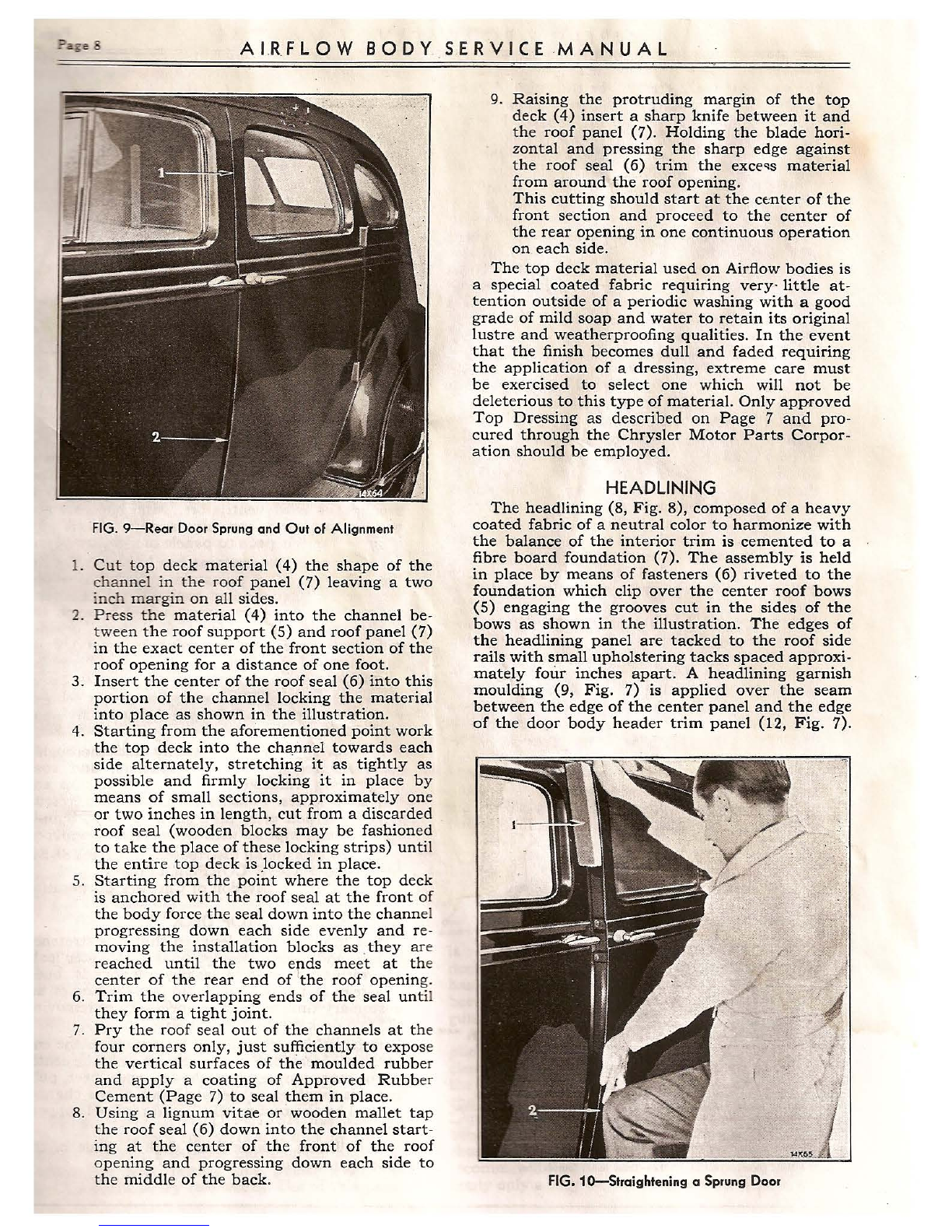
FIG. 9-Rear Door Sprung and Out of Alignment
1. Cut top deck material (4) the shape of the
channel in the roof panel (7) leaving a two
inch margin on all sides .
2. Pr ess the material (4) into the channel be-
twee n the roof support (S) and roof panel (7)
in the exact center of the front section of the
roof opening for a distance of one foot.
3. Insert the center of the roof seal (6) into this
portion of the channel locking the material
into place as shown in the illustration .
4. Starting from th e aforementioned point work
the top deck into the channel towards each
side alternately, stretching it as tightly as
possible and firmly locking it in place by
means of small sections, approximately one
or two inches in length, cut from a discarded
roof seal (wooden blocks may be fashioned
to take the place of these locking strips) unt il
the entire top deck is _locked in place.
5. Starting from the point where the top deck
is anchored with the roof seal at the front of
the body force the seal down into the chann el
progressing down each side evenly and re-
moving the installation blocks as .they are
reached until the two ends meet at th e
center of the rear end of the roof openin g.
6. Trim the overlapping ends of the seal unti l
they form a tight joint.
7. Pry the roof seal out of the channels at the
four corners only, just sufticiently to expos e
the vertical surfaces of the moulded rubber
and apply a coating of Approved Rubb er
Cement (Page 7) to seal them in place.
8. Using a lignum vitae or wooden mallet tap
the roof seal (6) down into the chann el start -
ing at the cent er of the front of the roof
opening and progressing down each side to
the middle of the back .
9. Raising the protruding margin of the top
deck (4) insert a sharp knife between it and
the roof panel (7). Holding the blade hori-
zontal and pressing the sharp edge against
the roof seal (6) trim the exce~s material
from around the roof opening .
This cutting should start at the ce:nter of the
front section and proceed to the center of
the rear opening in one continuous operation
on each side.
The top deck material used on Airflow bodies is
a special coated fabric requiring very- little at-
tention outside of a periodic washing with a good
grade of mild soap and water to retain its original
lustre and weatherproofing qualities . In the event
that the finish becomes dull and faded requiring
the application of a dressing , extreme care must
be exercised to select one which will not be
deleterious to this type of material. Only approved
Top Dressing as described on Page 7 and pro-
cured through the Chrysler Motor Parts Corpor -
ation should be employed.
HEADLINING
The headlining (8, Fig . 8), composed of a heavy
coated fabric of a neutral color to harmonize with
the balance of the interior trim is cemented to a
fibre board foundation (7). The assembly is held
in place by means of fasteners (6) riveted to the
foundation which clip over the center roof bows
(S) engaging the grooves cut in the sides of the
bows as shown in the illustration . The edges of
the headlining panel are tacked to the roof side
rails with small upholstering tacks spaced approxi-
mately four inches apart. A headlining garnish
moulding (9, Fig. 7) is applied over the seam
between the edge of the center panel and the edge
of the door body header trim panel (12 , Fig. 7).
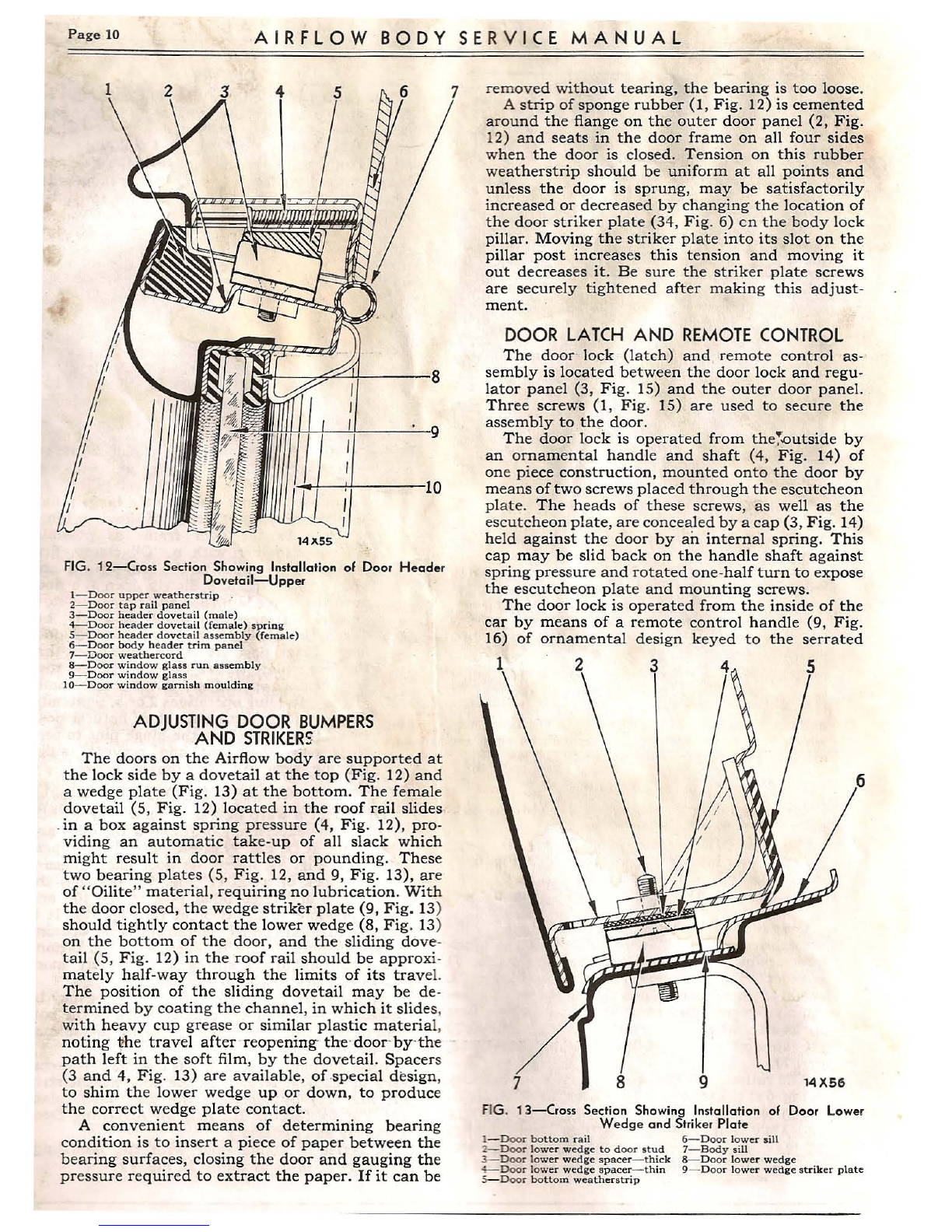
FIG.10-Straightening a Sprung Door

FIG. 11-Door Properly Straightened and Aligned
This moulding is held in place with wood screws
and washers (8, Fig. 7).
DO NOT APPLY CLEANING SOLUTIONS
OF ANY NATURE TO SPECIAL COATED
HEADLINING - SEE SPECIAL INSTRUC-
TIONS FOR CLEANING ON PAGE 5.
The headlining trim panel is supplied by the
Chrysler Motors Parts Corporation for replace-
ment purposes approximat ely one-half inch larger
in all dim ensions than the opening in the roof. It
is important that th ese panels be carefully marked
and cut to exactly fit the opening in the body into
which it is to be installed, inasmuch as they are
not interchangeable from one body to another.
UPPERBODYTRIMPANELS
All trim material above the line of the belt
moulding, consisting of th e following:
Windshi eld head er trim panel (5, Fig. 6)
Front door hinge pillar trim pan el (3, Fig. 6)
Door body header trim panel (12, Fig. 6)
Center pillar trim panel upp er (11, Fig . 6)
Upper qua rter trim pan el (16, Fig. 6)
Ov er rear window trim panel (21, Fig. 6)
are fabricated in the sam e manner as the head-
linin g, namely, a specia l coated fabric (10, Fig. 7)
is cemented to a fibre board foundation (14, Fig. 7).
All of th ese panels are held in place, for as-
sembly, by means of small tacks driven into trim
sticks after which the garnish mouldings (9, Fig. 7)
are applied with garn ish moulding screws (8,
Fig. 7).
Th e various mou lding s are indicated very clearly
in Fig. 6 at (7), (8), (9),(13), (15), (17), (19)and(22) .
DO NOT APPLY CLEANING SOLUTIONS
OF ANY NATURE TO SPECIAL COATED
TRIM MATERIAL - SEE SPECIAL IN -
STRUCTIONS FOR CLEANING ON PAGE 5.
DOORS
The correct ~ psition of a door is determ_ined _by
the alignment of the moulding on the body w~th
that on the door (Fig. 9 illustrates a door which
has become sprung throw ing the moulding out of
alignment) and by the uniformity of the clearance
between the door frame and door on all four sides
when closed. The door must not interfere with the
metal of the door frame at any point.
The doors on Airflow bodies are quite rigid
st ruc tures, but if they become _warped or spru~g,
may be straightened by applying th e following
methods:
CAUTION : Lower the glass as far as possible.
I. Lateral adjustments of the door .may be
.. made .by loosening the screws in the body
· pillar half of th e hinge plate and sliding them
"in" or "out" on their elongated holes.
2. The lock side of the door may be raised or
lowered by placing the end of a wrench ·or
suitable flat tool between the hinge leav es,
closing the door ~arefully until the ~ing e. is
sprung sufficient ly to move the door mto -1ts
desired position. This ·operation will also
adjust the door closer to the lock pillar. ·
3. To adjust the door closer to the hinge pillar,
bind the protruding leaves of the door hinge
as close to the door frame as possible ,
securely together with a " C" clamp, first
protecting the finish on the hing e plates and
body from scratches. Slowly open the door
until the hinge is sprung sufficiently to close
up any excessive gap whic h may exist be-
tween the back of the door and the door
hinge pillar post. It is recomm ended that
the hinge plate screws be loosened one turn
and the door opened and closed several times
after performing operations 2 or 3, tightening
them without disturbing their natural posi -
tion. 1.'!lis will permit the hinge pins to seek
their own alignment and prevent undue
binding, wear and objectionable noises.
WARPEDDOORS
To correct a warp in a door such as that indi-
cated by the excessive gap between the door and
door frame at (2, Fi g. 9) as compared to the open-
ing at (1, Fig. 9), lower th e door glass, place a
padded block of wood (1, Fig. 10) between the
door frame and latch pillar post at th e top an d
apply pressure to the door at (2, Fi g. 10). It is
possible to obtain perfect alignment of the opening
in this manner if care is taken when performing
this operation to not spring the door any more
than necessary to obtain a perf ect fit.
An excessive gap at the top of the door may be
corrected by plac ing the padded block at the bot-
tom of the door latch pillar app lying pr essure at
the top of the door.
After springing a door in this manner it is neces-
sary to readjust tension on the door weatherstrip
(1, Fig. 12) by reset ting the door latch plate
(34, Fig. 6). (See instructions for Adjusting Door
Bumpers and Strikers.)
A perfectly fitting door with the mouldings
correctly lined -up is shown in Fig. 11.
Page 10 AIRFLOW BODY SERVICE MANUAL
1
l--- -----"'--'-+------8
I
I
I
14Jl55
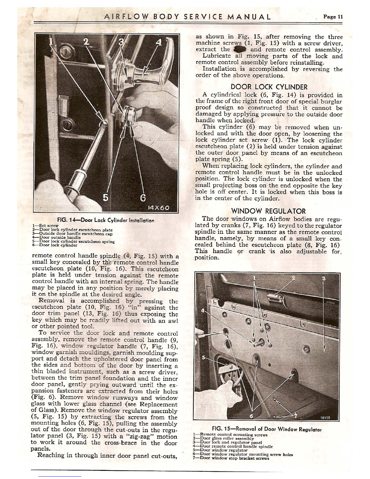
FIG. 12-Cros s Section Showing Installation of Door Header
Dovetail-Upper
1- D oor upper weathe rstrip .
2- Door tap rail panel
3-Doo r header dovetail (male)
4- Door header dovetail (female) spring
S- Door header dovetail assembly (female)
6-Door body header trim panel
7- Door weathercord
8-Door wind ow glass run assembly
9- Doo r window glass
IO- Door window garnish moulding
ADJUSTING DOOR BUMPERS
AND STRIKERS
The doors on th e Airflow body are supported at
the lock side by a dovetail at the top (Fig. 12) and
a wedge plate (Fig. 13) at the bottom. The female
dovetail (5, Fig. 12) located in the roof rail slides
.in a box against spring pr essure (4, Fig. 12), pro-
viding an automatic tak e-up of all slack which
might result in door rattl es or pounding. These
two bearing plates (5, Fig. 12, and 9, Fig. 13), ar e
of "Oilite " material, requiring no lubrication. With
th e door closed, the wedge striker plate (9, Fig. 13)
should tightly contact the lower wedge (8, Fig . 13)
on the bottom of the door, and the sliding dove -
tail (5, Fi g. 12) in the roof rail should be approxi-
mately half-way through the limits of its travel.
The position of the sliding dovetail may be de-
termined by coating the channel, in which it slide s,
with heavy cup grease or simi lar plastic materia l,
noting 1lhe travel after reopening the ·doo r by·the
path left in the soft film, by the dovetail. Spacer s
(3 and 4, Fig. 13) are available, of .special design,
to shim the lower wedge up or down, to produce
the correct wedge plate contact.
A conv enient means of determining bearing
condition is to ins ert a piece of paper between the
bearing surfaces, closing the door and gauging the
pressure required to extract the paper. If it can be
removed without tearing, the bearing is too loose .
A strip of sponge rubber (1, Fig. 12) is cemented
around the flange on the outer door panel (2, Fig.
12) and seats in the door frame on all four sides
whe n the door is closed. Tension on this rubber
weatherstrip should be uniform at all points and
unless the door is sprung, may be satisfactorily
increased or decreased by changing the location of
the door striker plate (34, Fig. 6) en the body lock
pillar. Moving the striker plate into its slot on the
pillar post increases this tension and moving it
out decreases it. Be sure the striker plate screws
are securely tighten ed after making this adjust-
ment.
DOOR LATCH AND REMOTECONTROL
The door · lock (latch) and . remote control as-
sembly is located between the door lock and regu-
lator panel (3, Fig. 15) and the out er door panel.
Three screws (1, Fig. 15) are used to secure the
assembly to the door .
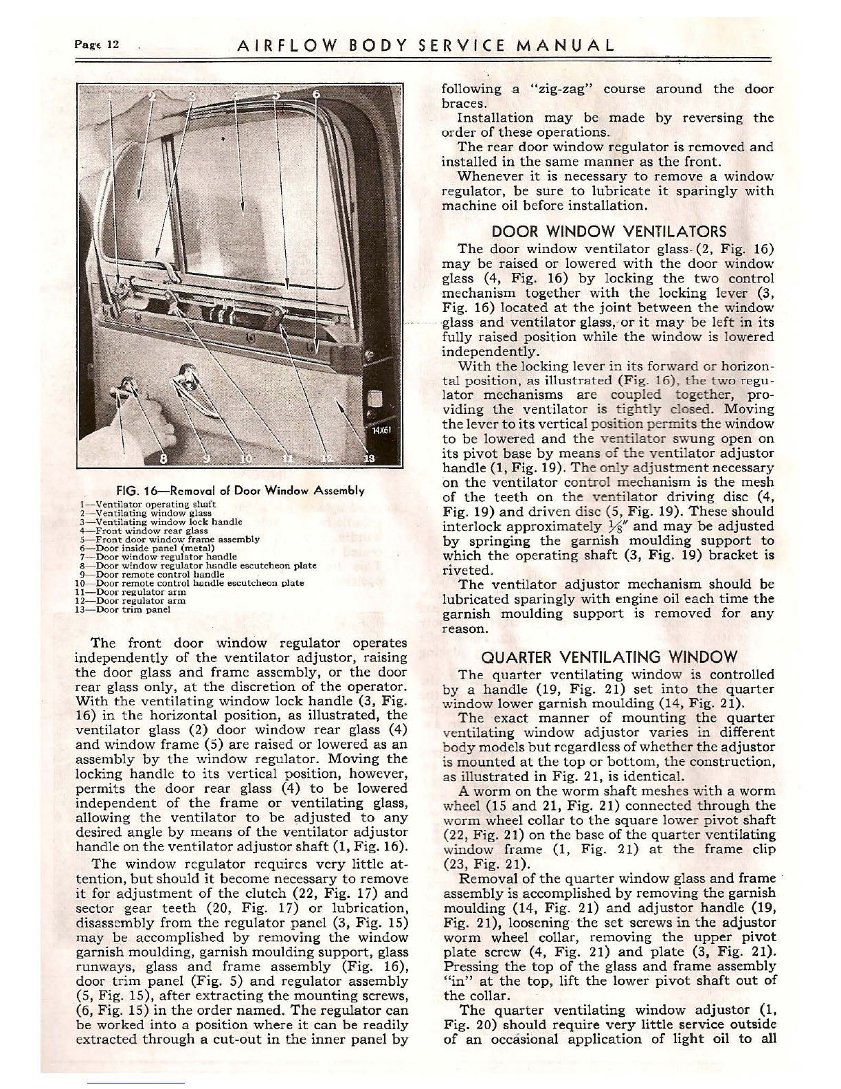
The door lock is operated from the;.outside by
an ornamental handle and shaft (4, Fig. 14) of
one piece construction, mounted onto the door by
means of two screws placed through the escutcheon
plate . The heads of these screws, as well as the
escutcheon plate, are concealed by a cap (3, Fig. 14)
held against the door by an internal spring. This
cap may be slid back on the handle shaft against
spring pres sure and rotated one-half turn to expose
the escutch eon plat e and mounting screws.
The door lock is operated from the inside of the
car by means of a remote control handle (9, Fig.
16) of ornamental design keyed to the serrated
1 3
6
7 8 9 14X56
FIG. 13-Cross Section Showing Installation of Door Lower
Wedge and Striker Plate
1- Doo r bottom rail 6- Door lower sill
2-D oor lower wedg e to door stud 7- Body sill
3--Door low er wedg e spacer - thick 8- Door lower wedge
4--Door lower wedge spacer - thin 9- Door lower wedge striker plate
~D oor bo ttom weatherstr ip
AIRFLOW BODY SERVICE MANUAL Page 11
FIG. 14-Door Lock Cylinder Installation
1-S et screw
2-Door lock cylinder escutcheon plate
3-0utside door handle escutcheon cap
4-Door outside handle
S--Door lock cylinder escutcheon spring
6-Door lock cylinder
remote control handle ~pindl c:;(4, Fi g. 15) with a
small key concealed by :tl,1.j: "remote control handle
escutcheon plate (10, Fig. 16). T his escutcheon
plate is held under tension against the remote
control handle with an intern al sprin g. The handle
may be placed in any position by merely placing
it on the spindle at the desired angle.
Removal is accomp lished by pressing the
escutcheon plate (10 , Fig. 16) "in" against the
door trim panel (13, Fig. 16) thus exposing the
key which may be readi ly lifted out with an awl
or other point ed too l.
To service the door lock and remote control
assembl y, remove the remote control handle (9,
Fig. 16), window regu lator handle (7, Fig. 16),
window garnish mou ldin gs, garnish moulding sup -
port and detach the uphol stered door panel from
th e sides and bottom of the door by inserting a
thin blad ed instrument, such as a screw driver,
between the trim panel foundation and the inner
door panel, gently prying outward until the ex-
pansion fastene rs are ext racted from their holes
(Fig. 6). Remove window runways and window
glass with lower glass channel (see Replacement
of Glass) . Remov e the win dow regulator assembly
(5, Fig. 15) by extra cting the screws from the
mounting holes (6, Fig. 15), pulling the assembly
out of the door through the cut-outs in the regu-
lator panel (3, Fig. 15) with a "zig-zag" motion
to work it around the cross-brace in the door
panels.
Reaching in through inner door panel cut-outs,
as shown in Fig. 15, after removing the three
machine screws (1, Fig. 15) with a screw driver,
extract the • and remote control assembly .
Lubricate all moving parts of the lock and
remote control assembly before reinstalling.
Installation is accomplished by reversing the
order of the above operations .
DOOR LOCK CYLINDER
A cylindrical lock (6, Fig. 14) is provided in
the frame of the right front door of special burglar
proof design so constructe9 that it cannot be
damag ed by applying pressure to the outside door
handle when locked.
This cylinder (6) may be removed when un-
locked and with the door open, by loosening the
lock cylinder set screw (1). The lock cylinder
escutcheon plate (2) is held under tension against
the outer door panel by means of an escutcheon
plate spring (5).
When replacing lock cylinders, the cylinder and
remote control handle must be in the unlocked
position. The lock cylinder is unlocked ·when the
small projecting boss on the end opposite the key
hole is off center . It is locked when this boss is
· in the center of the cylinder.
WINDOW REGULATOR
The door windows on Airflow bodies are regu-
lated by cranks (7, Fig. 16) keyed to the regulator
spindle in the same manner as the remote control
handle, namely, by m eans of a small key con-
cealed behind the escutcheon plate (8, Fig. 16)
This handle 9r crank 'is also adjustable for.
.position.
FIG. 15-Removal of Door Window Regulator
1-R em ote cont rol mount in g screws
2-Door glass roll er assemb ly
3-D oor lock and regu lat or panel
4- Door re mote control handl e spindle
5-Door window regu lat or
6-Door window regu lato r mounting screw holes
7-Door window atop bracket screws
PagE- 12 AIRFLOW BODY SERV I CE MANUAL
FIG. 16-Removal of Door Window Assembly
I- Ventilator operating shaft
2- Ventilating window glass
3- Ventilating windo w lock handle
4- Front window rear glass
5-Front door window frame assembly
6- Door inside panel (metal}
7-Door window regulator handle
8-Door window regulat or handle escutcheon plate
9- Door remote control handle
10-Door remote control handle escutcheon plate
11-Door regulator arm
12-Door regulator arm
13- Door trim panel
The front door window regulator operates
independently of the ventilator adjustor, raising
the door glass and frame assembly, or the door
rear glass only, at the discretion of the operator.
With the ventilating window lock handle (3, Fig.
16) in the horizontal position, as illustrated, the
ventilator glass (2) door window rear glass (4)
and window frame (5) are raised or lowered as an
assembly by the window regulator. Moving the
locking handle to its vertical position, however,
permits the door rear glass (4) to be lowered
independent of the frame or ventilating glass,
allowing the ventilator to be adjusted to any
desired angle by means of the ventilator adjustor
handle on the ventilator adjustor shaft (1, Fig. 16).
The window regulator requires very little at -
tention, but should it become necessary to remove
it for adjustment of the clutch (22, Fig . 17) and
sector gear teeth (20, Fig . 17) or lubrication,
disassembly from the regulator panel (3, Fig. 15)
may be accomplished by removing the window
garnish moulding , garnish moulding support, glass
runways, glass and frame assembly (Fig. 16),
door trim panel (Fig. 5) and regulator assembly
(5, Fig. 15), after extracting the mounting screws,
(6, Fig . 15) in the order named. The regulator can
be worked into a position where it can be readily
extracted through a cut-out in the inner panel by
following a "zig -zag" course around the door
braces.
Installation may be made by reversing the
order of these operations.
The rear door window regulator is removed and
installed in the same manner as the front.
Whenever it is necessary to remove a window
regulator, be sure to lubricate it sparingly with
machine oil before installation.
DOOR WINDOW VENTILATORS
The door window ventilator glass- (2, Fig. 16)
may be raised or lowered with the door window
glass (4, Fig. 16) by locking the t wo control
mechanism together with the locking lever (3,
Fig. 16) located at the joint between th e window
· glass ·and ventilator glass, or it may be left in its
fully raised position while the window is lowered
independently.
With the locking lever in its forward or horizon -
tal positio n, as illustrat ed (F ig. 16) , the two regu-
lat or mechanisms are coupled to gethe r, pro-
viding the ventilator is tightly closed . Moving
the lever to its vertica l position permit s th e window
to be lowered and the ventilator swung open on
its pivot base by me ans of the ventilat or adjustor
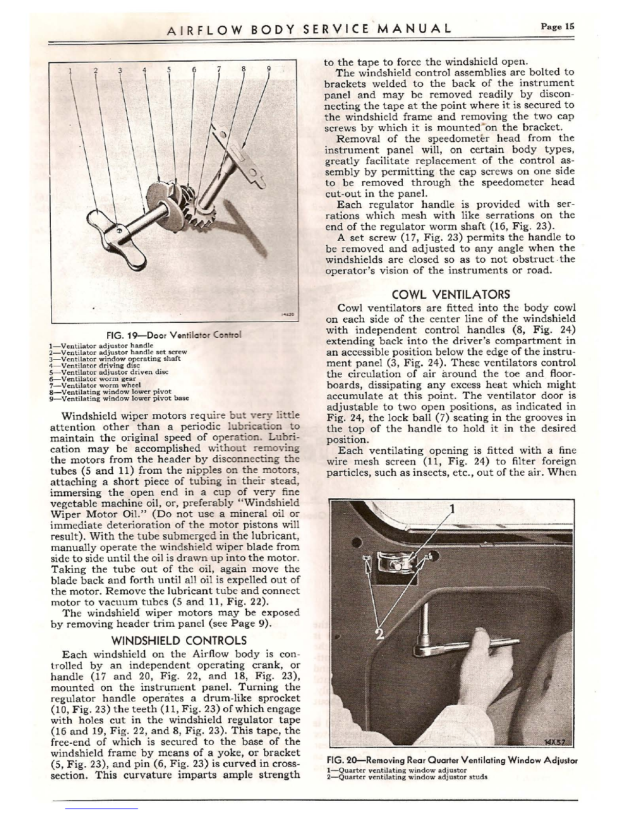
handle (1, Fig. 19). T he only adjust ment necessary
on the ventilator con trol mec hanism is the mesh
of the teeth on the venti lator driving disc (4,
Fig . 19) and driven dis c (5, Fig. 19). These should
interlock approxim ately ½" and may be adjusted
by springing th e garnish moulding support to
which the operat ing shaft (3, Fig . 19) bracket is
riveted .
The venti lator adjustor mechanism should be
lubricated sparingly with engine oil each time the
garnish moulding support is removed for any
reason.
QUARTERVENTILATINGWINDOW
Th e quarter ventilating windo w is controlled
by a handle (19, Fig. 21) set into the quarter
window lower garnish moulding (14, Fig. 21).
The exact manner of mounting the quarter
ve ntilating window adjustor varies in different
body models but regardless of whether the adjustor
is mounted at the top or bottom , the construction,
as illustrated in Fig . 21, is identica l.
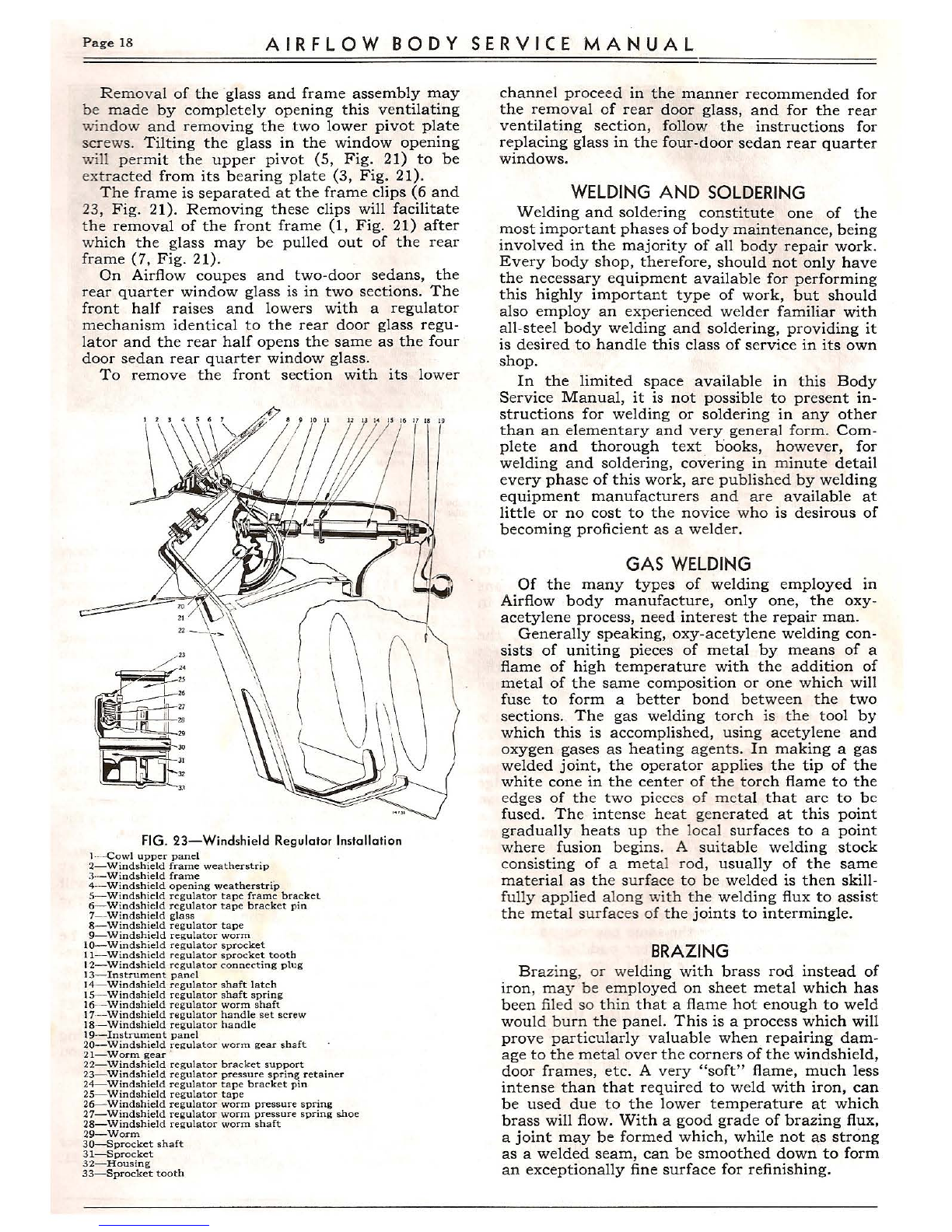
A worm on the worm shaft meshes wit h a worm
wheel (15 and 21, Fig. 21) connected through the
worm wheel collar to the square lower pivot shaft
(22, Fig. 21) on the base of the quarte r ventilating
window frame (1, Fig. 21) at the frame clip
(23, Fig. 21).
Removal of the quarter window glass and frame ·
assembly is accomplished by removing the garnish
moulding (14, Fig . 21) and adjustor handle (19,
Fig. 21), loosening the set ·screws in the adjustor
worm wheel collar, removing the upper pivot
plate screw (4, Fig. 21) and plate (3, Fig. 21).
Pressing the top of the glass and frame assembly
"in" at the top, lift the lower pivot shaft out of
the collar .
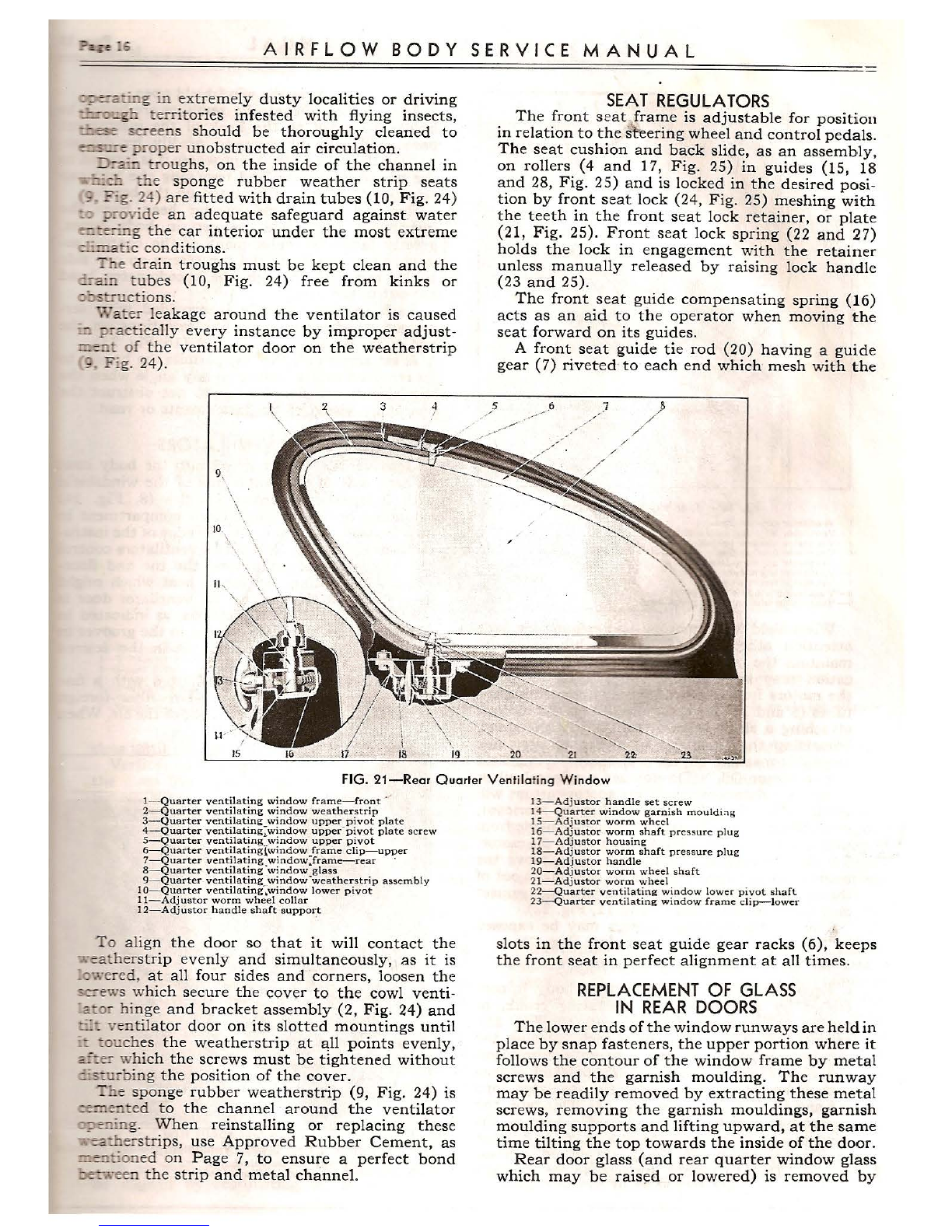
The quarter ventilating window adjustor (1,
Fig. 20) should require very little service outside
of an occasional application of light oil to all

A I RFL O w BO D y sERV I CE M A N uA L Page 13
10 11
12 13 14 16 18 14X31
19 20 21 22
FIG. 17-Front Door Window Regulator and Ventilating Operating Mechanism
I-Window fram e
2- Ventilating window loc king cam
3- Ventilating window fram e
4-V entilat ing window loc kin g ca m striker plate
5-Ventil at ing win dow weat h erstr ip
6- W ind ow supp ort
8-V ent ilator driven dis c
9- Ventil at or worm ret ainer plat e
10- Ventil ator driv ing disc
11-W ind ow fr ame cha nne l
12-Wind ow re gulat or a ssembly
13-Window lower glass channel and bracket assem bly
14-- W indow wea the rstrip
16-Wi ndow regula t or gears
17-Win dow regulator arm
18- Window supp ort
19-Ven til ating win do w latch bar
20--Wi ndow regul ator sector
21- W ind ow lower glas s channel bracket
22- Window regul ator clutch
7-Ven tilating window lower pivot assembly 15- Window re gul ator plate
bearing and gear tooth surfaces. Should it become
necessary to remove this assembly, however, it is
only necessary to remove the rear quarter lower
trim panel foundation, at the end of the rear seat
cushion, after loosening the arm rest suppor t
assembly, unscrewing the studs (2, Fig . 20) and
loosening the worm wheel shaft collar set scre ws.
To install, reverse the order of these operations .
WINDSHIELD
The windshields are mounted on tw o adjus tabl e
hinges, as illustrated in Fig. 22, on th e inside of
the windshield header bar .
Slots are pro vided in th e windsh ield hinge
brac ket s (1, Fig . 22) at the windshield bracket to
header screws (9, Fig. 22) and in the windshield
hinge- female (3, Fig. 22) at the windshield hinge
to bracket screws (8, Fig. 22), permitting the wind-
shield glass and frame assembly to be adjusted
to any position.
A sponge rubber weatherstrip is cemented into
th e windshield opening to prevent the entrance
of water or dust into the car interior.
Tension on this weatherstrip should be uniform
on all four sides and corners of the windshield
frame. Adjustment is accomplished by loosening
the screws which secure the hinges to the header
board, sliding the hinge plates on their elongated
Page 14 A I.R F L O W BO D Y SERV IC E M A N U A L
5 6 7
'.,.
8 9 11 12
I
1· (,.;,,
21 22
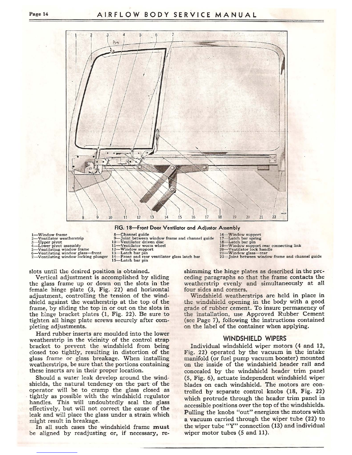
FIG. 18-Front Door Ventilator and Adjustor Assembly
1-Window frame 8-Chann el guide
2-Ventila tor weatherstrip
3-Upp er piv ot 9-Joint between window frame and cha nn el guide
10- Ventilator driven disc
16-- Window support
17- Latch bar sp ring
18-L atch bar pin
11- Ventilator worm wheel
12-Wind ow su pport
13- Latch bar pin
19-W indow support rear con nectinii link
20-Ventilator lock handle
21-Window glass- rear
4-Low er pivot assemb ly
5-Venti latin g window frame
6-Vent ila ting window glass- front
1-Ventilating window locki ng plunger 14- Front and rear ventilator glass lat ch bar
15-Latch bar pin 22-Joint between window frame and channel guide
slots until the desired position is obtained.
Vertical adjustment is accomplished by sliding
the glass frame up or down on the slots in the
femal e hing e plat e (3, Fig. 22) and horizontal
adjustment, controlling the tension of the wind-
shield against the weatherstrip at the top of the
frame, by sliding the top in or out on the slots in
the l:foge bracket plates (1, Fig. 22). Be sure to
tighten all hinge plate screws securely after com-
pleting adjustments.
Hard rubber inserts are moulded into the lower
weatherstrip in the vicinity of the control strap
bracket to prevent the windshield from being
closed too tightly, resulting in distortion of the
glass fram e or glass breakage. When installing
weatherstrips, be sure that the portions containing
these inserts are in their proper locati on.
Should a water leak develop around the wind-
shields, the na tural tend ency on the part of the
operator will be to cramp th e glass closed as
tightly as possible with the windshield regulator
hand les. This will undoubt edly seal the glass
effectively, but will not correct the cause of the
leak and will place the glass under a strain which
might result in breakage.
In all such cases the windshield frame must
be aligned by readjusting or, if necessary, re-
shimming the hinge plat es as described in the pre-
ceding paragraphs so that the frame contacts the
weatherstrip evenly and simultaneously at all
four sides and comers .
Windshie ld weather strips are held in place in
the windshie ld opening in the body with a good
grade of rubber cement. To insure permanency of
the installation , use Approved Rubber Cement
(see Page 7), following the instructions contained
on the label of the container when applying.
WINDSHIELDWIPERS
Individual windshield wiper motors (4 and 12,
Fig. 22) operated by the vacuum in the intake
manifold (or,fuel pump vacuum booster) mounted
on the inside of the windshield header rail and
concealed by the windshield header trim panel
(S, Fig. 6), actuate independent windshield wiper
blades on each windshield. The motors are con-
trolled by separate control knobs (18, Fi g. 22)
which protrude through the header trim panel in
accessible positions over the top of the windshields.
Pulling the knobs "out" energizes the motors with
a vacuum carried through th e wiper tube (22) to
the wiper tube "Y" connection (13) and individual
wiper motor tubes (5 and 11).
AIRFLOW BODY SERVICE MANUAL Page 15
FIG. 19-Door Ven tilcrtor Control
1-Ventiiator adjuster handle
2-Ventilator adjuster handle set scre w
3-Ventilator window operating shaft
4- Ventilator driving disc
5-Ventilator adjuster driven disc
6-Ventilator worm gear
7-Ventilator worm wheel
8-Ventilating window lower pivot
9-Ven t ilating window lower pivot base
Windshield wiper motors req uire but \·e:·y :ittl e
attention other than a periodic lubrication to
maintain the original speed of opera tion. Lub ri-
cation may be accomplished without removin g
the motors from the header by disconn ecting th e
tubes (S and 11) from the nipp les on th e moto rs,
attaching a short piece of tub ing in their st ead,
immersing the open end in a cup of very fine
vegetable machine oil, or, preferably " Windshie ld
Wiper Motor Oil." (Do not use a mineral oil or
immediate deterioration of th e motor pistons will
result). With the tube submerged in the lubricant,
manually operate the windshield wiper blade from
side to side until the oil is drawn up into the motor.
Taking the tube out of the oil, again move the
blade back and forth until all oil is expelled out of
the motor. Remove the lubricant tube and connect
motor to vacuum tubes (5 and 11, Fig. 22).
The windshield wiper motors may be exposed
by removing header trim panel (see Page 9).
WINDSHIELD CONTROLS
Each windshield on the Airflow body is con -
trolled by an independent operating crank, or
handle (17 and 20, Fig. 22, and 18, Fig. 23),
mounted on the instrument panel. Turning the
regulator handle operates a drum-like sprocket
(10, Fig. 23) the teeth (11, Fig. 23) of which engage
with holes cut in the windshield regulator tape
(16 and 19, Fig. 22, and 8, Fig. 23). This tape, the
free-end of which is secured to the base of the
windshi eld frame by means of a yoke, or bracket
(5, Fig . 23), and pin (6, Fig. 23) is curved in cross-
section. This curvature imparts ample strength
to the tape to force the windshield open.
The windshield control assemblies are bolted to
brackets welded to the back of the instrument
panel and may be removed readily by discon-
necting the tape at the point where it is secured to
the windshield frame and removing the two cap
screws by which it is mounte cr on the bracket .
Removal of the speedometer head from the
instrument panel will, on certain body types,
greatly facilitate replacement of the control as-
sembly by permitting the cap screws on one side
to be removed through the speedometer head
cut-out in the panel.
Each regulator handle is provided with ser-
rations which mesh with like serrations on the
end of the regulator worm shaft (16, Fig. 23).
A set screw (17, Fig. 23) permits the handle to
be removed and adjusted to any angle when the
windshields are closed so as to not obstruct .the
operator's vision of the instruments or road.
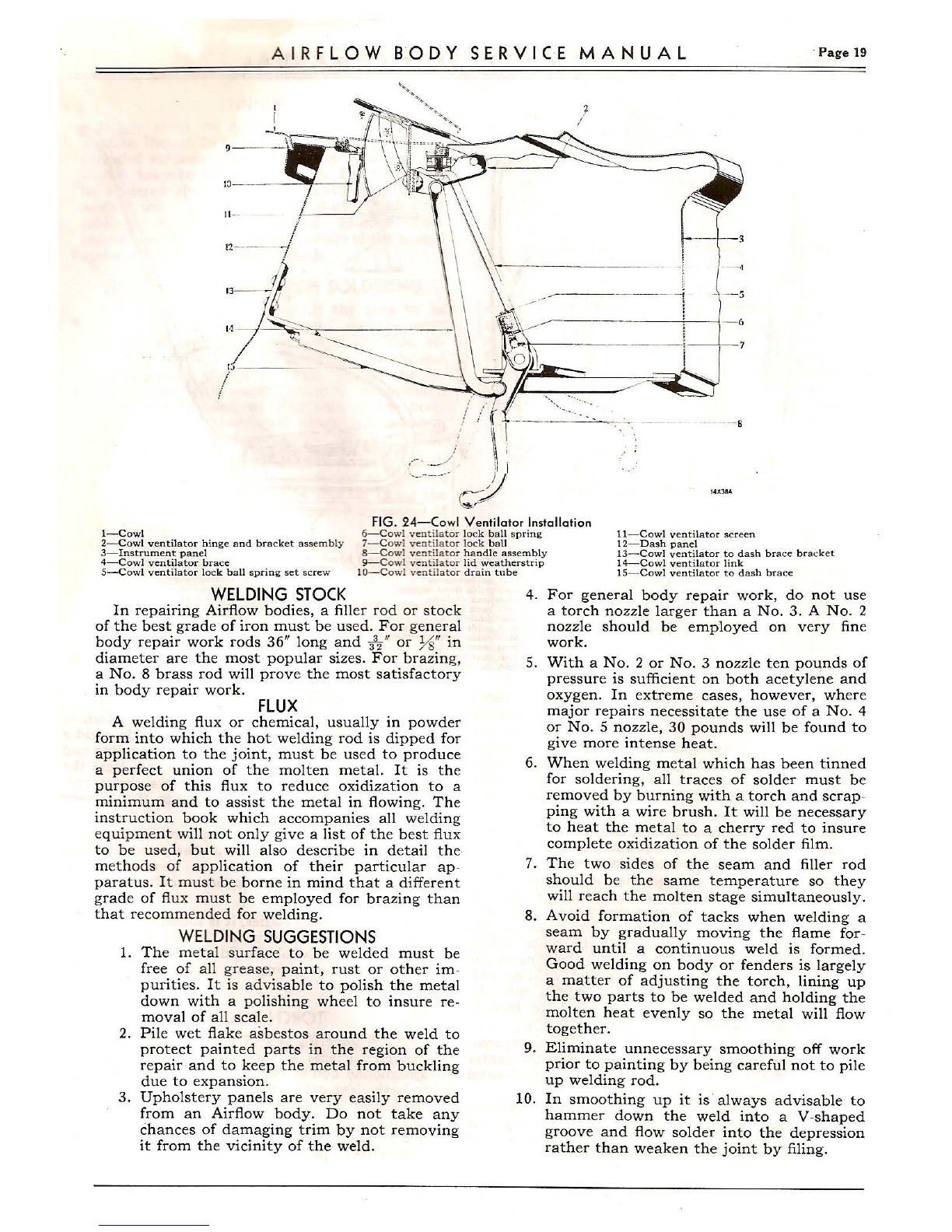
COWL VENTILATORS
Cowl ventilators are fitted into the body cowl
on each side of the center line of the windshield
with independent control handles (8, Fig. 24)
extending back into the driver's compartment in
an accessible position below the edge of the instru-
ment panel (3, Fig. 24). These ventilators control
the circulation of air around the toe and floor-
boards, dissipating any excess heat which might
accumulate at this point . The ventilator door is
adjustable to two open positions, as indicated in
Fig. 24, the lock ball (7) seating in the grooves in
the top of the handle to hold it in the desired
position.
Each ventilating opening is fitted with a fine
wire mesh screen (11, Fig. 24) to filter foreign
particles, such as insects, etc., out of the air. When
FIG. 20-Removing Rear Ouarter Ventilating Window Adjustor
1-Quarter ventil ating window adjuster
2-Quarter ventilating wind ow adjustor studs
AIRFLOW BODY SERVICE MANUAL
~~:i::::. g :nextremely dusty localities or driving
:..::..-;::,::.s=. !:errito ries infested with flying insects ,
::.::_=s:=-sc:-eens should be thoroughly cleaned to
=-~-=-=-=:;i:-oper unobstructed air circulation.
:J:-a::..:::tro ughs, on the inside of the channel in
=~the sponge rubber weather strip seats
; _? :g. 24) are fitted with drain tubes (10, Fig. 24)
:::; ~=-o·,"lde an adequate safeguard against water
~:e7:.:i g the car interior under the most extreme
-·=- ,,,tic conditions.
:' ne dr ain troughs must be kept clean and the
::...-a:.ntubes (10, Fig. 24) free from kinks or
;:;::i:s:::-uctio ns.
7/a ter leakage around the ventilator is caused
::: :;i:-acti cally every instance by improper adjust -
==.e::t of the ventilator door on the weatherstrip
; . F :g. 24).
9,'
\
10
\
\
2
'\ 3 4
SEATREGULATORS
The front seat frame is adjustable for position
in relation to the s~ ering wheel and control pedals.
The seat cushion and back slide, as an assembly ,
on rollers (4 and 17, Fig. 25) in guides (15, 18
and 28, Fig. 25) and is locked in the desired posi -
tion by front seat lock (24, Fig. 25) meshing with
the teeth in the front seat lock retainer, or plate
(21, Fig. 25). Front seat lock spring (22 and 27)
holds the lock in engagement with the retainer
unless manually released by raising lock handle
(23 and 25).
The front seat guide compensating spring (16)
acts as an aid to the operator when moving the
seat forward on its guides.
A front seat guide tie rod (20) having a guide
gear (7) riveted to each end which mesh with the
)
/
/ /
FIG. 21-Rear Quarter Ventilating Window
1- Quarter ventilating window frame-front
2-Quarter ventilating window weatherstrip
3-Quarter ventilating window upper pivot plate
4-Quarter ventilating :window upper-pivot plate screw
5-Quarter ventilating window upper pivot
6-Quarter ventilat ing{window frame clip-upper
7-Quarter ventilating windowJrame-rear ·
8-Quarter ventilating ·window glass
9-Quarter ventilating window ·weatherstrip assembly
I a-Quarter ventilat ing~window lower pivot
11-Adjustor worm wheel collar
12-Adjustor handle shaft suppor _t
To align the door so that it will contact the
.....-eath erstrip evenly and simultaneously, as it is
:o-;,,·ered , at all four sides and corners, loosen the
;;cew s which secure the cover to the cowl venti-
:c.:o:- hinge and bracket assembly (2, Fig. 24) and
:::'.': ventil ator door on its slotted mountings until
::: ::ouche s the weatherstrip at all points evenly,
_;__:°:e:- which the screws must be tightened without
::.:_s::ar bing the position of the cover.
T::ie sponge rubber weatherstrip (9, Fig. 24) is
~ ::::.e:::ited to the channel around the ventilator
=9e::.:.:1g. When reinstalling or replacing these
- ~:.:.,ers tri ps, use Approved Rubber Cement, as
==.:::::-.::o::1ed on Page 7, to ensure a perfect bond
.:i.~een th e strip and metal channel.
13-A dj ustor handle set screw
14-Quarter window garnish mouldi;-ig
15- Adjustor worm wheel
16-Adjustor worm shaft pressure pl u g
17-Adjustor housing
18- Adjustor worm shaft pressure plu g
19- Adjustor handle
20-Adjust or worm wheel shaft
21-Adjustor worm wheel
22-Quarter ventilating window lower pivot shaft
23-Quarter ventilating window frame clip-lower
slots in the front seat guide gear racks (6), keeps
the front seat in perfect alignment at all times .
REPLACEMENTOF GLASS
IN REARDOORS
The lower ends of the window runways are held in
place by snap fasteners, the upper portion where it
follows the contour of the window frame by metal
screws and the garnish moulding. The runway
may be readily removed by extracting these metal
screws, removing the garnish mouldings, garnish
moulding supports and lifting upward, at the same
time tilting the top towards the inside of the door.
Rear door glass (and rear quarter window glass
which may be rais~d or lowered) is removed by

A I R FiL O W B O D Y SE RV I C E M A N U A L Page 17
FIG. 22-Complete Windshield Installation, with Trim Panels Removed
1-Windshield hinge bracke t
2-Windshield hinge male outer
3- Windsh ield hinge female
4-Windshield wiper
5-Windshield wiper tube
6- Windshield glass
7-Windshicld side channel
8-Wi ndsh ield hinge to bracket screw 16- Windshield regulator tape
17- Windshield regulator handle
18-Windshield wiper control knob
19-Windshield regulator tape
20-Windshield regulator handle
21-Windshield wiper bracket
22-Windshield wiper tube
J 9-Windsh icld bracket to header screw
IO-Win dshi eld hi nge pin
11- Win d sh icld w ipe r tube
12-Win d shi eld wi per
13- Win d sh ield wipe r tub e "Y" coupling
14-W ind shield wipe r tube "Y" coupling nipple
15-W ind shicl d glass
first removing the garnish mo ulding , garnish
moulding support and window run ways after
which the glass should be slowly raise d by means
of the regulator handle (7, Fig. 16) and tilted in
at the top, as indicated in Fig. 16.
When the window is completely raised , the
regulator arms (11 and 12, Fig. 16) will meet, as
shown by the dotted lines in the center of the
lower channel, permitting the glass and frame
assembly to be lifted out of the door.
Installation of the glass in the lower channel is
accomplished by supporting the channel (6, Fig. 26
on wooden blocks (7, Fig. 26), laying a sufficient
number of layers of anti-squeak (5, Fig. 26) along
the top of the glass channel. Lay the lower edge
of the glass along the groove in its proper position
and applying a wooden block (3, Fig. 26) with a
padded groove (1, Fig. 26) along the upper edge,
tap lightl y with a lignum vitae or wooden mallet
(2, Fig. 26).
The glass should be tight enough so that the
lower channel cannot be removed by hand. It is
important tha t the groove in the block (3, Fig . 26)
be of approxima tely the same contour as the top
of the glass, and that sufficient padding be used to
absorb the shock of the mallet blows.
It is also possible to drive the glass into the
channel by laying the block (3, Fig. 26) on the
bench with the groove up, putting the top of the
glass into the padded slot and driving the channel
onto the glass with a ~allet. Car e must be exer-
cised, however, in doing so to keep from damaging
the channel with the force of the blows.
REPLACEMENT OF GLASS
IN FRONT DOORS
The door glass assembly, including the ven-
tilator, should be removed from the door in the
same manner as the glass assembly for rear doors
after placing the ventilator locking lever (20,
Fig. 18) in a horizontal position. The ventilator
glass, (6,) is removed from the complete double
glass assembly, as follows:
1. Move locking lever to vertical position and
rotate ventilator glass to the wide open
position by turning the driven disc (10).
2. Remove two screws which attach the lower
pivot (9, Fig. 19), and spring the outside
glass frame slightly so as to release the glass
frame from the pivot plate.
3. Slide the glass frame off the glass, using care to
not break the frame at the corner~. Springing
the vertical portion of the frame aids in this
operation and relieve strain at the corners.
The large glass (21, Fig. 18) is removed from the
comp lete double glass assembly, as follows:
1. Move the locking lever to vertical position.
2.~ ull the upper an d lo-Ner channels apart at
t:he, joints , 9 and 22, Fig. 18). The glass will
follow the lower cha nnel and slide out of the
upper section, as shown tn Fig. 17.
The rubbe r weather st rip (2, Fig. 18) may be
removed, after the ventila t or glass has been re-
moved, by pressing the lower pivot shaft (4, Fig .
18) out of the gear (11, Fig. 1~). Use of a suitable
gear puller on this opera t ion will avoid damage
to th e parts. The weathers trip may then be pulled
out of the window frame channe l. When installing
this weatherstrip, soapy wat er serves as a good
lubricant for the rubber and fa cilitates assembly.
'I,
REPLACEMENTOF GLASSIN
REARQUARTERWINDOWS
The rear quarter window glass in four-door
sedans operates on a pivot, as illustrated in Fig. 21.
Page 18 AIRFLOW BODY SERVICE MANUAL
Remova l of the ·glass and frame assembly may
be made by completely opening this ventilating
windo w and removing the two lower pivot plate
screws. Tilting the glass in the window opening
will permit the upper pivot (5, Fig . 21) to be
extracted from its bearing plate (3, Fig . 21) .
The frame is separated at the frame clips (6 and
23, Fig. 21). Removing these clips will facilitate
the removal of the front frame (1, Fig. 21) after
which the glass may be pulled out of the rear
frame (7, Fig. 21).
On Airflow coupes and two-door sedans, the
rear quarter window glass is in two sections. The
front half raises and lowers with a regulator
mechanism identical to the rear door glass regu-
lator and the rear half opens the same as the four
door sedan rear quarter window glass.
To remove the front section with its lower
FIG. 23-Windshield Regulator Installation
1-- -Cowl upper panel
2-W:indshield frame weatherstrip
3-- Windshield frame
4-Windshield opening weatherstrip
5-Windshield regulator tape frame bracket
6-Windshield regulat or tape bracket pin
7--Windshield glass
8- Windshield regulator t ape
9-Windshield regulator worm
10- Windshield regulator sprocket
I I-Windshield regulator sprocket tooth
12-Windshield regulator connecting plug
13-lnstrument panel
14-Windshield regulator shaft latch
15--Windshield regulator shaft spring
16- Windshield regulator worm shaft
17-- Windshield rogulator hand le set screw
18-Windshield regulator handle
19- Instrument panel
20- Windshiel d regulator worm gear shaft
21- Worm gear ·
22-Windshield regulator bracket support
23-Windshie ld regulator pressure spr ing retainer
24-Windshield regulator tape bracket pin
25-Windshield regulator tape
26-Windshield regulator worm pressure spring
27- Windshield regulator worm pressure spring shoe
28-Windshield regulator worm shaft
29-Worm
30---Sprocket shaft
31- Sprocket
32-Housing
33-Sprocket tooth
channel proceed in the manner recommended for
the removal of rear door glass, and for the rear
ventilating section, follow the instructions for
replacing glass in the four-door sedan rear quarter
windows.
WELDINGAND SOLDERING
Welding and soldering constitute one of the
most important phases of body maintenance, being
involved in the majority of all body repair work.
Every body shop, therefore, should not only have
the necessary equipment available for performing
this highly important type of work, but should
also employ an experienced welder familiar with
all-steel body welding and soldering, providing it
is desired to handle this class of service in its own
shop .
In the limited space available in this Body
Service Manual, it is not possible to present in-
structions for welding or soldering in any other
than an elementary and very general form. Com-
plete and thorough text books, however, for
welding and soldering, covering in minute detail
every phase of this work, are published by welding
equipment manufacturers and are available at
little or no cost to the novice who is desirous of
becoming proficient as a welder.
GAS WELDING
Of the many types of welding employed in
Airflow body manufacture, only one, the oxy-
acetylene process, need interest the repair man.
Generally speaking, oxy -acetylene welding con-
sists of uniting pieces of metal by means of a
flame of high temperature with the addition of
metal of the same composition or one which will
fuse to form a better bond between the two
sections. The gas welding torch is the tool by
which this is accomplished, using acetylene and
oxygen gases as heating agents. In making a gas
welded joint, the operator applies the tip of the
white cone in the center of the torch flame to the
edges of the two pieces of metal that arc to be
fused . The intense heat generated at this point
gradually heats up th e local surfaces to a point
where fusion begins. A suitable welding stock
consisting of a meta l rod, usually of the same
material as the surfac e to be welded is then skill-
fully applied along with the welding flux to assist
the metal surfac es of the joints to intermingle.
BRAZING
Braz ing, or welding with brass rod instead of
iron, ma y be employed on sheet metal which has
been filed so thin that a flame hot enough to weld
would burn the panel. This is a process which will
prove particularly valuable when repairing dam-
age to the metal over the corners of the windshield,
door frames, etc. A very "soft" flame, much less
intense than that required to weld with iron, can
be used due to the lower temperature at which
brass will flow. With a good grade of brazing flux,
a joint may be formed which, while not as strong
as a welded seam, can be smoothed down to form
an exceptionally fine surface for refinishing.
A IR FLOW 8 0 DY SERVI CE MANUAL · Page 19
II -
'-···- -··
-3
~--------J J=:
~ - ---- 1----!I :
-- -- ~.- - - ---·-. ··- - ---s
1-Cowl FIG. 24-Cowl Ventilator Installation
6-C owl ventilator lock ball spring 11- Cowl ventilator scr een
12- Dash panel7-C owl venti lato r lock ball2-Cowl ventilator hinge and bra cket assemb ly
3- lnstrument panel
4-Cowl ventilator brac e
5-Cowl ventilator lock ball spring set screw
8-Cowl ventilat or handle assembl y
9-C owl ventilator lid weatherstrip
IO-C owl ventil ato r d rain tube
13- Cowl vent ilat or t o dash bra ce bra cket
14- Cowl ventilator link
15-Cowl ventilat or to d ash brace
WELDINGSTOCK
In repairing Airflow bodies, a filler rod or stock
of the best grade of iron must be used. For general
body repair work rods 36" long and 3\" or ½" in
diameter are the most popular sizes. For brazing,
a No. 8 brass rod will prove the most satisfacto ry
in body repair work. FLUX
A welding flux or chemical, usually in powder
form into which the hot welding rod is dipp ed for
application to th e joint, must be used to produce
a perfect union of the molten metal. It is the
purpose of this flux to reduce oxidization to a
minimum and to assist th e metal in flowing. The
instruction book which accompanies all welding
equipm ent will not only give a list of the best flux
to be used, but will also describe in detail the
method s of application of their particular ap -
paratus. It must be borne in mind that a different
grade of flux must be employ ed for brazing than
that recomm ended for welding.
WELDINGSUGGESTIONS
1. The meta l surface to be welded must be
free of all greas e, paint, rust or other im -
purities . It is advisable to polish the metal
down with a polish ing wheel to insure re-
moval of all scale.
2. Pile wet flake asbe stos around the weld to
protect paint ed parts in the region of th e
repair and to keep the meta l from bucklin g
due to expansion.
3. Upholstery panels are very easily removed
from an Airflow body. Do not tak e any
chances of damaging trim by not removing
it from the vicinity of the weld.
4. For general body repair work, do not use
a torch nozzle larger than a No. 3. A No. 2
nozzle should be employed on very fine
work.
5. With a No. 2 or No. 3 nozzle ten pounds of
pressure is sufficient on both acetylene and
oxygen. In extreme cases, however, where
major repairs necessitate the use of a No. 4
or No. 5 nozzle, 30 pounds will be found to
give more intense heat.
6. When welding metal which has been tinned
for soldering, all traces of solder must be
removed by burning with a torch and scrap -
ping with a wire brush. It will be necessary
to heat the metal to a cherry red to insure
complete oxidization of the solder film.
7. The two sides of the seam and filler rod
shou ld be the same temperature so they
will reach the molten stage simultaneously.
8. Avoid formation of tacks when welding a
seam by gradually moving the flame for -
ward until a continuous weld is formed .
Good welding on body or fenders is largely
a matter of adjusting the torch, lining up
the two parts to be welded and holding the
molten heat evenly so the metal will flow
together .
9. Eliminat e unnecessary smoothing off work
prior to painting by being careful not to pile
up welding rod.
10. In smoothing up it is always advisable to
hammer down the weld into a V-shaped
groove and flow solder into the depression
rather than weaken the joint by filing.

Pa.ge 20 AIRFLOW BODY SERVICE MANUAL
2 :3 4 G 7 8 13
I \ I /
Z? /
I \
I
I
I
/
FIG. 25- FrontSeat Frame and Adjustment Mechan ism
I-Front seat cushion sup port assembly
2- F ront seat frame
3- Front seat support rear
4--Fro nt seat gu ide roller assembly
11-Fron t seat guide-low er
12- Front sea t guide front support
13- Fro nt seat back cushion
21- ? = =t Joe.kin g reta iner
22- F==: seat lock spring
23- ? :=: 5eat lock handle
2-<- ? =. : seat lock
5 -Front seat guide te e rod assembl y
6 - Front seat guide gear rack assem bly
7- Fro nt seat gui de gear
· 14-Fr ont seat back frame
15- Front seat guide-u p per
16-Front seat guide compensating spring
17- Front seat guide roller assembly
18- Front seat lower guide
25-- i' :-o::t seat lock ha ndle
:5---F =t seat guide lock shaft
:i-F:-o::;: seat guid e lock spring
:~ F =t seat lower guide
7,1---F".oar board
8- Front seat gu ide - uppe r
9- Front seat cushion suppor t
JO- Front seat guide roller 19-Front seat gear rack
20-Front seat tie ro d assembly
11. Pillar posts or braces may become so badly
bent that straightening wou ld be impossible
without weakening the structure . In any
such case it is adv isable to cut the damaged
portion of the post out with a hack saw or
torch and weld a new piece into place fabri-
cated from metal of approximately the same
thickness.
12. If it is necessa ry to straighten the body at a
point where the metal has becom e thin, cut
out the weakened section and weld into
place a she et steel plate of appro ximatel y
the same thickness. In fitting the plate to
the openin g, allow a clearanc e on all sides
equal to the gauge or thickn ess of the
metal. Secure the plate in place before
welding around the edges by tacking at the
four corners with torch and welding rod.
A section of rod may be welded onto the
center of the sheet by whi ch to hold it
while making these tacks.
13. To break a spot weld, driil a hole approxi -
mately / 6 11 in diameter throu gh the center
of the weld, prying the two pieces of metal
apart with a cold chisel.
To reunite these panels, drill addi tio nal
holes along the point of th e union , gas
welding the edges of eac h aperture and
fillin g them with welding stock .
HEATING AND SHRINKING
To re mo\-e a ding or low spot from a panel where
it is impossib le to get at it from the inside, weld a
piece of welding wire to the center of the ding and
form a handle in the free end of the rod. Heat the
area on and around the low spot to a ch erry red ,
pulling the ding or low spot out to the contour
of the body .
To hea t shrink a pan el, heat a small area in
the cent er of the buckl e to a cherry re d. Ho lding
a dolly block underneath t he heated portion,
hammer lightly with a wooden mallet until the
metal is cool.
In welding stee l bodies , it is foun d that the con-
traction of the metal is far greater than the ex-
pansion. This detail should be considered when
lay ing out or planning any repairs requiring th e
use of a torch.
TORCH SOLDERING
Torch soldering is a process by means of which
uneven surfaces or deep, sharp indentations in
automobile bodies may be filled with solder so as
to have clean cut contours. The solder is heated to
the proper temperatur e by means of a gas or blow
torch, applied to the depression in the body pan el
and the heated metal paddl ed to an even surface
with wooden paddl es or blocks .
Table of contents


