DEL RollEasy Operation and maintenance manual

RollEasy
SAFETY SLATTED AUTOMATIC COVER
INSTALLATION NOTICE Installation / Use / Maintenance / Safety Advice
SWIMMING POOL DEVELOPMENT AND INNOVATION
Notice Roll-Easy GB Non-Norm 2009 11:MP 07/01/2010 14:37 Page 1
www.delbrece.com.ua
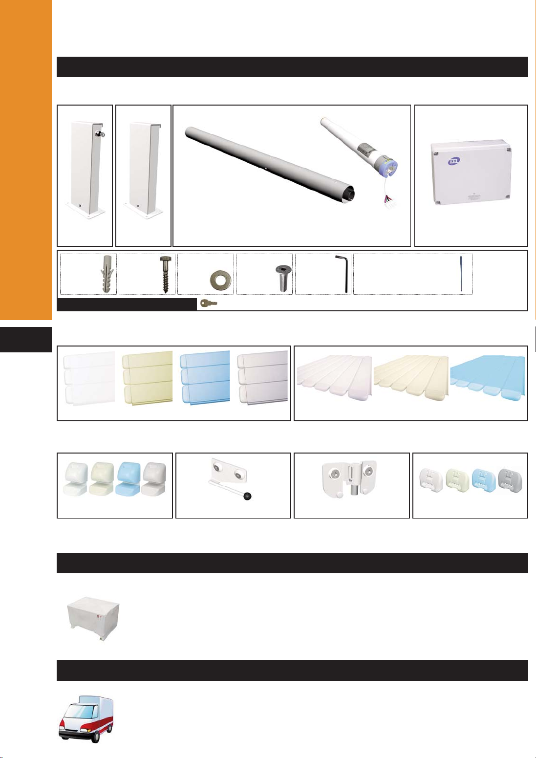
PARTS INCLUDED IN THE DELIVERY
TRANSPORT
PACKING LIST
Description
THIS NOTICE MUST BE GIVEN TO THE POOL OWNER
PLEASE READ CAREFULLY AND KEEP IN A SAFE PLACE
Roll-Easy (2 boxes - Supports + Tube)
Slats (model, colour and number of boxes according to your order)
OPTION - Safety locking kit “according to your order” (1 box)
example - for a 5 x 10 m pool with Ø3 m step unit
Supports : 1 box of 0.50 x 0.45 x 0.35 m --- 20 Kg
Tube : 1 box of 0.20 x 5.30 m --- 25 Kg
Slats : 5 box of 0.25 x 0.20 x 5.00 m --- 250 Kg
Locking kit : 1 box of 0.30 x 0.20 x 0.20 m or 0.75 x 0.25 x 0.15 m --- 5 KG
Total weight : 300 Kg
In any event the consignment must be checked by the recipient upon receipt of the
delivery. Any damage or shortage should be reported to the supplier within 24 hours.
Motor
support
x1
Electric control panel
Spare parts bag
Free side
support
x1 x1 x1
Anodised aluminium tube Ø130 mm 4 mm thick
+ Tubular motor 120 Nm (in the tube)
x8
Screw
M10x60
x8
Sleeve
Ø12
x2
Screw
M5x20
x8
Washer
M10
x1
Key
(for automatic stops)
x1
Allen key
n°4
2 keys
Quick-Lock
3 fitting models : surface mounted - Insert mounted - Hanging mounted
Strap locking kit Lock-it Push-lock
69 mm slats 54 mm slats
2
Notice Roll-Easy GB Non-Norm 2009 11:MP 07/01/2010 14:37 Page 2
www.delbrece.com.ua

INFORMATION
For pools up to 5 x 11 m + Ø3 m step unit
The motor is located in the tube and must be installed
on the support equipped with the key switch.
The electrical supply comes
from the electric control
panel in the plant room.
Automatic stops are adjusted directly on the motor.
A torque limiter device protects the system in
case of any excessive resistance to the covers
operation.
The cover is made of watertight PVC slats that
float on the water.
Information
NECESSARY TOOLS - (INSTALLATION - 2 PERSONS)
THE ABOVE GROUND COVER
Ø8 - 12 - 20
n°13
n°17
OPTION
Safety locking kits
Gap between the
wall and the cover
Motor conform to
electrical standards
Key switch with
maintained contact
during locking
PVC slats
Tube
Nb
turn/mn
Torque
Dimension in cm
Serial nb
Voltage
Engine
power
Amps
21
48
35,2
12
IP45 3
Notice Roll-Easy GB Non-Norm 2009 11:MP 07/01/2010 14:37 Page 3
www.delbrece.com.ua

TUBE MOUNTING
MOTOR INSTALLATION
Installation
5 mm 5 mm
Tube adjustment
A too little adjustment does not allow dilatation in
case of temperature variation.
Screw
TFHC
M5x20
Insert the motor and move it around until it fits
inside the motor bearing
Automatic stops are
located upwards
Take the door of the motor side support off
4
Allen key n°4
Free side
Motor side
Tube
Notice Roll-Easy GB Non-Norm 2009 11:MP 07/01/2010 14:37 Page 4
www.delbrece.com.ua
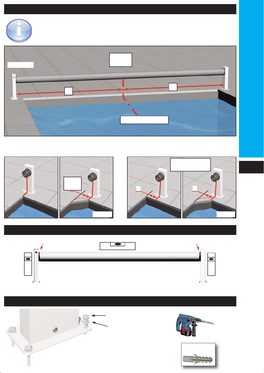
TUBE INSTALLATION
LEVEL ADJUSTMENT
SETTLEMENT
With strap locking kits, Lock-it and Push-lock With Quick-lock
AA
Min A = 15 cm
Max A = 60 cm
Max
60 cm
cornerscorners
Adjust according to the pool corners and safety locking kits.
Locate the motor side support as per your order
Middle of the pool
AB
A = B
Motor side
Installation
5 mm 5 mm
Screw M10x60
Washer M10 Ø12
Sleeve Ø12
5
Notice Roll-Easy GB Non-Norm 2009 11:MP 07/01/2010 14:37 Page 5
www.delbrece.com.ua

ELECTRICAL DRAWING
Installation
4
+
-
5
6
3
2
Plug
Electrical supply 230 V
Torque limiter
device
Electric control
panel
Key switch
1 - Automatic stop supply
2 - Automatic stop supply
3 - Motor supply -
4 - Motor supply +
5 - Mains supply +
6 - Mains supply -
6
1
The electric control panel must be installed in a dry plant room.
The installation must comply with current electrical standards.
Ask your electrician or the electricity board for advice.
All our control panels are powered with single phase 230V (50Hz).
The input power required is 0.15 Kw.
Fit a circuit breaker equipped with a 30 mA RCD to protect the installation.
2 x 4 mm² - Up to 16 m long.
2 x 6 mm² - From 16 to 25 m long.
2 x 10 mm² - From 25 to 50 m long.
Notice Roll-Easy GB Non-Norm 2009 11:MP 07/01/2010 14:37 Page 6
www.delbrece.com.ua

COVER INSTALLATION
SKI INSTALLATION
Installation
Allen key
n°4
Cut out
Box stickered «début de volet»
Box stickered «escalier»
Install the slats on the water and
clip them together.
Take care with the direction of
the cover over the pool.
Skis are
always
mounted on
the last slat. They
stop the cover
«diving» when closing
over the pool.
+
Last slat
Box stickered
«fin de volet»
“CLAC”
Fit the slats along
the whole length.
Repeat wiggling/handling of the slats may be needed.
HOW TO TAKE OFF A SLAT AND END CAPS ?
69 mm slats
with a small screw driver
54 mm slats
7
female
male
12
35 cm
If necessary, cut the coping stones
to stop the slats rubbing during
opening and closing of the cover.
Box stickered «fin de volet»
Notice Roll-Easy GB Non-Norm 2009 11:MP 07/01/2010 14:37 Page 7
www.delbrece.com.ua
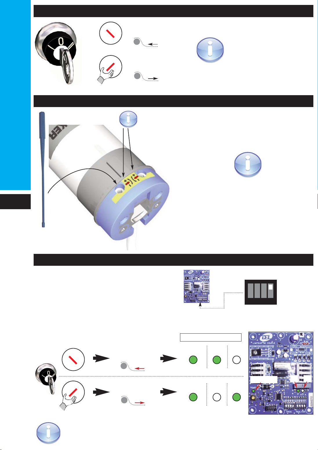
TORQUE LIMITER DEVICE CONTROL CHECKING
AUTOMATIC STOP ADJUSTMENT
Installation
Key
Red arrows indicate the direction of the cover.
maintained contact
Turn the key in the + direction to increase
the movement in the direction of the arrow.
Turn the key in the - direction to decrease
the movement in the direction of the arrow.
If the key switch is incorrectly wired refer to page 6.
I
0
II
I
0
II
Cover
opening
Cover
closing
- Close the electronic card
- Check :
1234
closed
O
O
Temoin
Temoin
F
F
O
Temoin F
LEDS
(Switch PROG)
ELECTRIC CONTROL CHECKING
If the electric control is
installed incorrectly, reverse
cables 1 and 2 outside the
motor (See page 6).
I
0
II
I
0
II
Cover opening
Cover closing
maintained contact
8
Notice Roll-Easy GB Non-Norm 2009 11:MP 07/01/2010 14:37 Page 8
www.delbrece.com.ua

Installation
9
ADJUSTEMENT OF THE SENSITIVITY (SWITCH PROG)
CARD ADJUSTMENT (SWITCH REGLAGE)
CONTROL TIME ADJUSTMENT (SWITCH REGLAGE)
1234
l<= 3 m
1234
l<= 4 m
1234
l<= 5 m
1234
l<= 6 m
1234
l<= 7 m
1234
l<= 8 m
1234
l<= 9 m
1234
l<= 10 m
l= pool width
L= pool length step unit included
1234
Roll-Easy
1234 1234
L<= 12 m L> 12 m
30 seconds 60 seconds
maximum sensitivity minimum sensitivity
Key switch with maintained contact during + 3 seconds
=
the next opening of the cover will be protected by the
automatic stops
Key switch with maintained contact during - 3 seconds
=
the next opening of the cover will not be protected by the
automatic stops
ACTIVATION (SWITCH PROG)
TESTER
IMPORTANT
1234
Open
in the event of an unexplained
activation, reduce the sensitivity
level by selecting the setting for
the next width up.
A- Block the cover by hand or with safety kits and open the cover.
closing
closing
=> The motor is automatically stopped
(If necessary adjust the sensitivity of the switch activation)
+than 3 sec
-than 3 sec
If you do not activate the torque limiter device, serious damages might
happen on the motor, the electric control box, the slats, and the
guarantee might not be applicable.
Activated
card
Opening, control in progress
Opening whithout control
Closing
Protection ON
OF
Witness
I
0
II
I
0
II
Notice Roll-Easy GB Non-Norm 2009 11:MP 07/01/2010 14:37 Page 9
www.delbrece.com.ua
Installation
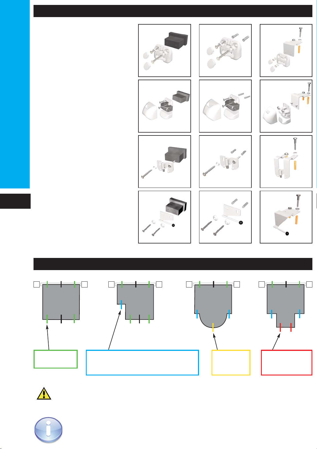
OPTIONAL SAFETY LOCKING KITS
LOCKING KIT POSITIONING
Quick Lock and Lock it cannot be installed on cut sides and rounded shapes,
except for the Roman end step unit.
Without step
unit With Roman
step unit
kit at the
end of the
step unit
2 kits at 50 cm
from the edge
kit at 50 cm
from the edge
1 kit centred if < 1 m
1 kit at 50 cm from the edge if < 2 m
2 kits if > 2 m
* X must not exceed 2 m
x* x x x
xxxx xxxx
x
With side step
unit With straight
or diagonal
step unit
Push-lock
Quick-lock
Lock-it
Strap locking
kit
Insert mounted Surface mounted
Surface mounted
Surface mounted
Surface mounted Hanging mounted
Hanging mounted
Hanging mounted
Hanging mounted
Insert mounted
Insert mounted
Insert mounted
10
Notice Roll-Easy GB Non-Norm 2009 11:MP 07/01/2010 14:37 Page 10
www.delbrece.com.ua

A water top level is mandatory
5 cm
min
5 cm
min
For concrete and panel pools
Screw VBA TF Z pozi
inox A4 Ø6 x 60
Screw cap
Screw cap
Washer Ø16
Wall unit
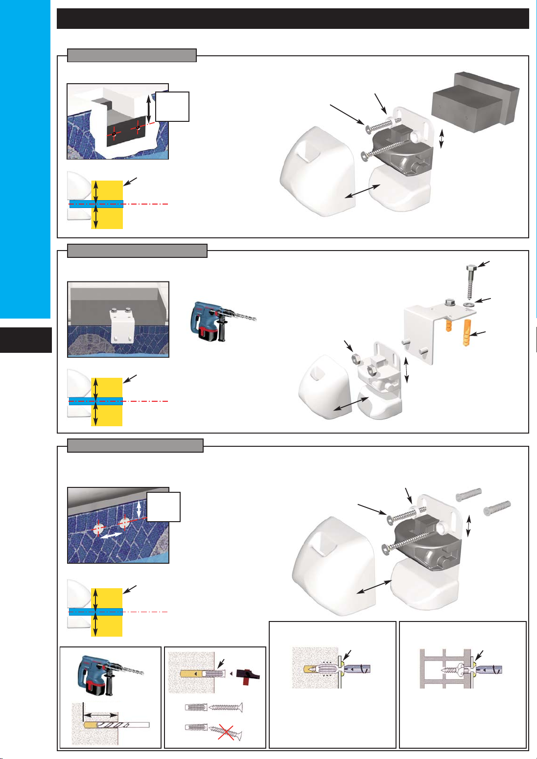
PUSH-LOCK INSTALLATION
Installation
For concrete pools
recommended
5 cm
Acceptable limit of
level variation
water level
5 cm
recommended
5 cm
Acceptable limit of
level variation
water level
5 cm
recommended
5 cm
Acceptable limit of
level variation
water level
5 cm
Hanging support Washer
Ø10
Screw
Inox A4
M10 x 60
Sleeve
nylon Ø12
Bolt A4 M10
Ø12
Ø8
5 cm
Sleeve 8 x 40
Screw VBA TF Z pozi
inox A4 Ø6 x 60
Washer Ø16
60 mm “minimum”
Sleeve
Washer
Do not tighten the
screws after the
resistance point, you
could damage the
installation.
Concrete
Once the resistance
point has been
reached, turn the
screw 3 times to finish
the installation.
Washer
Concrete blocks
Screw cap
For concrete pools and pools with a wall thicker than 8mm.
11
Surface mounted model
Hanging mounted model
Insert mounted model
Notice Roll-Easy GB Non-Norm 2009 11:MP 07/01/2010 14:37 Page 11
www.delbrece.com.ua
Installation
QUICK-LOCK INSTALLATION
A water top level is mandatory.
5 cm
min
5 cm
min
For concrete and panel pools
Screw VBA TF Z pozi
inox A4 Ø6 x 60
Washer Ø16
Wall unit
Adjustment
For concrete pools
recommended
5 cm
Acceptable limit of
level variation
water level
5 cm
recommended
5 cm
Acceptable limit of
level variation
water level
5 cm
recommended
5 cm
Acceptable limit of
level variation
water level
5 cm
Hanging support Washer
Ø10
Screw
A4
M10 x 60
Sleeve
nylon Ø12
Bolt A4 M10
Adjustment
Ø12
Ø8
For concrete pools and pools with a wall thicker than 8mm.
Sleeve 8 x 40
Adjustment
Screw VBA TF Z pozi
inox A4 Ø6 x 60
Washer Ø16
60 mm “minimum”
Sleeve
Washer
Do not tighten the
screws after the
resistance point, you
could damage the
installation.
Concrete
Once the resistance
point has been
reached, turn the
screws 3 times to
finish the installation.
Washer
Concrete blocks
12
Surface mounted model
Hanging mounted model
Insert mounted version
5 cm
Notice Roll-Easy GB Non-Norm 2009 11:MP 07/01/2010 14:37 Page 12
www.delbrece.com.ua

A water top level is mandatory.
5 cm
min
5 cm
min
For concrete and panel pools
Screw VBA TF Z pozi
inox A4 Ø6 x 60
Washer Ø16
Wall unit
LOCK-IT INSTALLATION
Installation
For concrete pools
recommended
5 cm
8 cm Acceptable limit of
level variation
water level
5 cm
Washer
Ø10
Screw
A4
M10 x 60
Sleeve
Ø12
Ø12
Ø8
For concrete pools and pools with a wall thicker than 8mm.
Sleeve 8 x 40
Screw VBA TF Z pozi
inox A4 Ø6 x 60
Washer Ø16
60 mm “minimum”
Sleeve
recommended
5 cm
8 cm Acceptable limit of
level variation
water level
5 cm
recommended
5 cm
8 cm Acceptable limit of
level variation
water level
5 cm
Washer
Do not tighten the
screws after the
resistance point, you
could damage the
installation.
Concrete
Once the resistance
point has been
reached, turn the
screws 3 times to
finish the installation.
Washer
Concrete blocks
13
Surface mounted model
Hanging mounted model
Insert mounted model
5 cm
Notice Roll-Easy GB Non-Norm 2009 11:MP 07/01/2010 14:37 Page 13
www.delbrece.com.ua
Installation
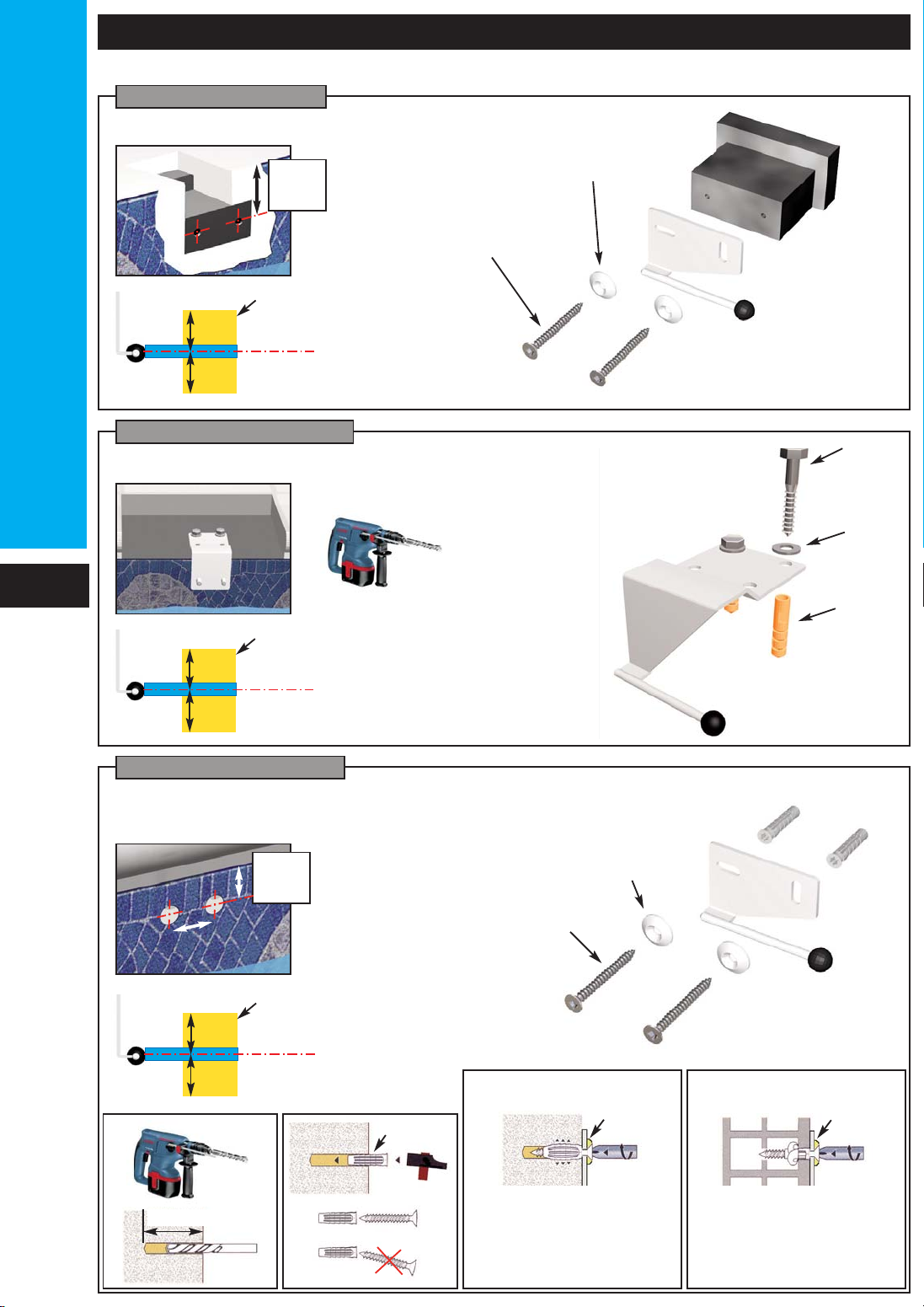
STRAP INSTALLATION
A water top level is mandatory.
5 cm
min
5 cm
min
For concrete and panel pools
Screw VBA TF Z
pozi inox A4 Ø6 x 60
Washer Ø16
Wall unit
For concrete pools
Washer
Ø10
Screw
Inox A4
M10 x 60
Sleeve
nylon Ø12
Ø12
Ø8
For concrete pools and pools with a wall thicker than 8mm.
Surface mounted model
Hanging mounted model
Insert mounted model
Sleeve 8 x 40
Screw VBA TF Z pozi
inox A4 Ø6 x 60
Washer Ø16
60 mm “minimum”
Sleeve
Washer
Do not tighten the
screws after the
resistance point, you
could damage the
installation.
Concrete
Once the resistance
point has been
reached, turn the
screws 3 times to
finish the installation.
Washer
Concrete blocks
recommended
5 cm
Acceptable limit of
level variation
water level
5 cm
recommended
5 cm
Acceptable limit of
level variation
water level
5 cm
recommended
5 cm
Acceptable limit of
level variation
water level
5 cm
14
5 cm
Notice Roll-Easy GB Non-Norm 2009 11:MP 07/01/2010 14:37 Page 14
www.delbrece.com.ua

INSTALLATION OF THE STRAP ANCHOR
INSTALLATION OF THE STRAP
Installation
Middle of the bracket
between 25
and 40 cm
Anchor for concrete deck
Anchor for wood deck
Ø20
Depth: 5 cm
Ø20
Depth : 4,5 cm
The anchor head
must be higher than
the pool deck surface
Do not force the anchor in a hole where
the diameter is smaller.
Screw Ø4 x 25
Sheath
Single strap
Strap
Sheath
Hook
Buckle
Tense the strap
The cover must be under the
bracket.
Install the hook after the buckle and tighten.
2 thicknesses of the strap go through the hook.
Double strap
tube side
HookBuckle
or
+++
1
1
2
Install the sheath around the hook and
heat with a hot air gun.
thermostat 5 to 6
Do not burn the strap.
3
15
Notice Roll-Easy GB Non-Norm 2009 11:MP 07/01/2010 14:38 Page 15
www.delbrece.com.ua

Use
OPENING/ CLOSING OF THE POOL
- Make sure there is no bather or foreign bodies in the pool before and during the closing action.
- When using an automatic cleaner under the cover, check that the hose does not affect the
movement of the slats when opening and closing the cover.
- It is essential to remove floating objects when opening and closing the cover.
- Do not resist the cover when opening and closing it.
- Do not activate the automatic cover when it is frozen/stuck.
- The cover can be opened and closed by one person. (3 minutes)
Opening :
- Release all safety locking kits
- Turn the key switch (position II).
- Keep away the items required to activate the cover (e.g. the key) out of children’s reach.
Always release the cover before starting the motor.
Closing:
- Turn the key switch (position I) «maintained contact during the closing»
- Lock all safety locking kits
- Keep away the items required to activate the cover (e.g. the key) out of children’s reach.
ALWAYS KEEP AN EYE ON THE POOL DURING OPENING OR CLOSING OF
THE COVER.
LOCKING AND RELEASING PUSH-LOCK
Locking
Releasing
16
Notice Roll-Easy GB Non-Norm 2009 11:MP 07/01/2010 14:38 Page 16
www.delbrece.com.ua

Use
LOCKING AND RELEASING LOCK-IT
LOCKING AND RELEASING QUICK-LOCK
Locking
Releasing
Locking
Releasing
with tool check the system is
locked
with tool The cover must not exit the
Quick Lock before you activate
the key switch.
17
+
+
Notice Roll-Easy GB Non-Norm 2009 11:MP 07/01/2010 14:38 Page 17
www.delbrece.com.ua

Permanent
LED
Use
LOCKING AND RELEASING STRAP SAFETY KIT
Locking
Releasing
Install the strap
between the wall
and the bracket
Lock the anchor
The strap must
be under
tension and
must be
through
the bracket
Release the anchor
Remove the strap from
around the bracket
and put it on the cover
WHAT TO DO IF THE SYSTEM STOPS (TORQUE LIMITER ACTIVATED)
18
Activated
card
Opening, control in progress
Opening whithout control
Closing
Protection ON
OF
Witness
Desactivated
card
Opening
Closing
OF
Witness Flashing
LED
1 - In the event of an explained stoppage during opening : (unreleased locking kits or
other...)
- Closed the cover for more than 3 seconds, until the tension of the cover is completely released.
(closed the cover for more than 3 seconds until the tension of the cover is completely released)
- Remove causes of stoppage, e.g. release locking kits and open the pool again.
2 - In the event of an unexplained stoppage :
- closer the cover between 1 and 3 seconds.
(The next opening will not be protected by the system)
- open the pool again.
If there are repeated activations, decease the sensitivity level..
- modify the adjustement if the sensitivity.(see page 9)
If you do not activate the torque limiter device, serious damages might happen on the
motor, the electric control box, the slats, and the guarantee might not be applicable.
Notice Roll-Easy GB Non-Norm 2009 11:MP 07/01/2010 14:38 Page 18
www.delbrece.com.ua

WINTER
MAINTENANCE
FILTRATION
UPKEEP
AXLE LUBRICANT
Use
- Clean your cover fully twice a year (start of season and start of winter).
This is even more important if you have hard water. If this is the case, use a high pressure cleaner
with warm water and a descaling product.
- Take the same care to clean the locking systems regularly.
- It is advisable to inspect the whole system, in the event of abnormal force on the cover.
(e.g. somebody falling)
- Check the straps every year.
- Shake the can well before use.
- Keep the can vertical. (see drawing)
- Apply the spray through the tube holes.
- Spray the lubricant 5 times for 1 second.
Do this operation during the installation and during the maintenance
- All work must be carried out by a professional who will contact the manufacturer if necessary.
- All spare parts must be originals.
- Inspect the whole cover for damage/wear and tear.
- It is necessary to check at the start of every season and in the case of accidents (dropping
something on it, hail on the cover, abnormal force on the cover, etc.) that the slats have not been
visibly damaged in such as way as to affect the cover’s operation (slats with cracks, holes,
deformations, etc.). Change the slats or the whole cover if necessary.
- In both summer and winter, do not cover the slats with a debris winter cover. “There is a risk of
damaging the slats due to a rise in temperature.”
- Check the straps (sewing) and the anti-abrasion sheath. Replace the strap or sheath if
necessary.
- Program the filtration during sunlight hours and run it continuously as soon as the water reaches
25ºC.
- Close the cover and prepare the pool for winter according to its geographic location, without
lowering the water level
WATER LEVEL OF THE POOL
- The water level has to be maintained at the correct level to avoid damage and repeated activa-
tion of the torque limiter device .(For more comfort, use a water level regulator).
- If the water level is too high, it might come from leaves in the skimmer.
- If the water level is too low, it might cause malfunction of the cover.
- In case of hand rails, the pool must be equipped with a water level.
19
Notice Roll-Easy GB Non-Norm 2009 11:MP 07/01/2010 14:38 Page 19
www.delbrece.com.ua

DEAR CUSTOMERS :
THANK YOU FOR CHOOSING A DEL AUTOMATIC COVER.
PLEASE READ CAREFULLY THE RECOMMENDATIONS BELOW
ZA La basse croix rouge 35530 Brécé FRANCE - tel : +33 2 99 00 25 62 - fax : +33 2 99 04 28 70 - E-mail : del.export@delbrece.fr
SWIMMING POOL BUILDER
SAFETY NOTICE
REMEMBER AND POST CLOSE TO THE SWIMMING POOL THE FIRST AID NUMBERS
- Fire station :
- Ambulance :
- Poisons centre:
CHILDREN CLOSE TO A SWIMMING POOL REQUIRE YOUR CONSTANT VIGILANCE AND YOUR ACTIVE MONITORING, EVEN IF
THEY CAN SWIM.
THE PHYSICAL PRESENCE OF A RESPONSIBLE ADULT IS ESSENTIAL WHEN THE POOL IS OPEN.
LEARN LIFE SAVING TECHNIQUES.
. THIS COVER DOES NOT REPLACE THE GOOD SENSE NOR WITH THE INDIVIDUAL LIABILITY. THE PURPOSE OF THIS COVER
DOES NOT REPLACE THE VIGILANCE OF THE PARENTS AND/OR THE RESPONSIBLE ADULTS WHICH REMAINS THE ESSENTIAL
FACTOR FOR YOUNG CHILDREN PROTECTION.
. BEWARE: SAFETY IS ASSURED ONLY WITH ONE CLOSED COVER, LOCKED AND CORRECTLY INSTALLED IN ACCORDANCE
WITH THE INSTRUCTIONS OF THE MANUFACTURER.
. THE COVER MUST BE SYSTEMATICALLY INSTALLED IN THE EVENT OF EVEN TEMPORARY ABSENCE OF THE RESIDENCE.
. MAKE SURE THERE IS NO BATHERS OR FOREIGN BODIES IN THE POOL BEFORE AND DURING CLOSING.
. PLACE THE NECESSARY TOOLS TO OPEN THE COVER OUT OF REACH CHILDREN. (THE KEY FOR EXAMPLE)
. THE OPENING ACTION OF THE MECHANISM SHOULD ONLY BE UNDERTAKEN BY A RESPONSIBLE ADULT.
. IT IS FORBIDDEN TO WALK OR JUMP ON THE SLATTED COVER.
. TAKE ALL MEASURES IN ORDER TO PREVENT THE ACCESS OF THE POOL TO YOUNG CHILDREN AND THIS UNTIL REPAIR OF
THE COVER OR WHEN NOTICING A DYSFUNCTION PREVENTING CLOSING AND THE SECURITY OF THE POOL.
. A CHILD MIGHT DROWN IN LESS THAN 3 MINUTES, AT LEAST ONE ADULT MUST SUPERVISE THE POOL WHEN IT IS OPEN.
Y/NOT20203 - 2009_11
Notice Roll-Easy GB Non-Norm 2009 11:MP 07/01/2010 14:38 Page 20
www.delbrece.com.ua
Table of contents


