Delhi Industries BI Series Parts list manual

Delhi Industries Inc. 523 James Street, Delhi, Ontario N4B 2Z3
Tel. (519) 582-2440 Fax. (519) 582-0581 www.delhi-industries.com
BI SERIES – UTILITY BLOWERS
OPERATION INSTRUCTIONS AND PARTS MANUAL
MODELS: BI-10 THROUGH BI-36, BI-10RM THROUGH BI-36RM
GENERAL SAFETY
Rotating parts on fans should not be exposed. Where these components are not protected by ductwork, cabinets or
covers, appropriate guards should be employed to restrict exposure to rotating parts. Access doors should not be
opened with the fan operating to avoid foreign objects being drawn into the system. On initial start-up a careful
inspection should be carried out to ensure no foreign material is present which could become airborne in the system.
Read installation and operation instructions carefully before attempting to install, operate or service Delhi BI/BI-RM
Series Blowers. Failure to comply with instructions could result in personal injury and/or property damage. Retain
instructions for future reference.
UNIT DESCRIPTION
DELHI BI series blowers are specifically designed as a quiet and efficient blower. The BI series incorporates a
backwardly inclined (BI) blade configuration to generate air moving performance. The BI series are single inlet blowers,
which have a standard CCW rotation and bottom horizontal discharge. The discharge direction may be easily altered to
any one of eight positions without removal of the wheel venturi or housing.
Complete access for motor and drive installations and servicing may be completed by partial removal of the drive
compartment cover assembly. Pre-lubricated ball bearings, motor adjustment hardware and a dynamically balanced
wheel are standard equipment. Operating temperature range is –65 to 220 deg. F.
Fig. 1
MODEL MAX. H.P SHAFT DIA. WEIGHT
BI-10/BI-10RM 2 ¾ 78
BI-12/BI-12RM 5 1 112
BI-13/BI-13RM 7-1/2 1 134
BI-15/BI-15RM 7-1/2 1 140
BI-16/BI-16RM 10 1-3/16 162
BI-18/BI-18RM 10 1-3/16 172
BI-20/BI-20RM 10 1-3/16 289
BI-22/BI-22RM 15 1-3/16 322
BI-24/BI-24RM 15 1-7/16 385
BI-27/BI-27RM 15 1-7/16 411
BI-30/BI-30RM 15 1-11/16 517
BI-33/BI-33RM 20 1-11/16 607
BI-36/BI-36RM 25 1-15/16 747
ALL SHAFTS ARE KEYWAYED
GENERAL
Inspect unit for damage, report any shipping damage to carrier. Check all fasteners and re-tighten as required. Rotate
the blower wheel by hand to ensure free rotation. If rubbing occurs, loosen the inlet venturi bolts, re-position the venturi
to establish clearance, re-tighten bolts.
Delhi Industries Inc. 523 James Street, Delhi, Ontario N4B 2Z3
Tel. (519) 582-2440 Fax. (519) 582-0581 www.delhi-industries.com
INSTALLATION
1. Secure the exhauster to the curb cap or sleepers (supplied by others) through the ¾” diameter holes provided in
the base of the motor compartment and leg. For proper motor compartment ventilation, if the unit is mounted on
a floor or solid surface, provide a minimum 1” clearance to the motor cabinet bottom. Install spring isolators or
duct isolators where required.
2. Complete all subsequent duct connections.
3. Rotate the blower wheel by hand. It should not rub against the housing inlet. If rubbing occurs, loosen the set-
screws on the wheel hub and shift the wheel to obtain clearance. Re-tighten all set-screws.
4. Insert the four motor nuts and bolts up through the bottom of the sliding motor platform to match the bolting
configuration of the motor to be installed. The master hole for smaller motor frames is located at the top left
hand corner of the motor platform furthest from the blower housing. The master hole for 213T, 215T and 254T
frame motors is 2” inset from the fore mentioned master hole for smaller frame motors.
5. Mount the blower sheave on the blower shaft and tighten its set-screw securely on the key of the shaft. (See
Table 1 for drive data).
6. Mount the motor sheave on the motor shaft. Leave some clearance between the pulley and the motor end bell.
Tighten the set-screws on the key of the motor shaft.
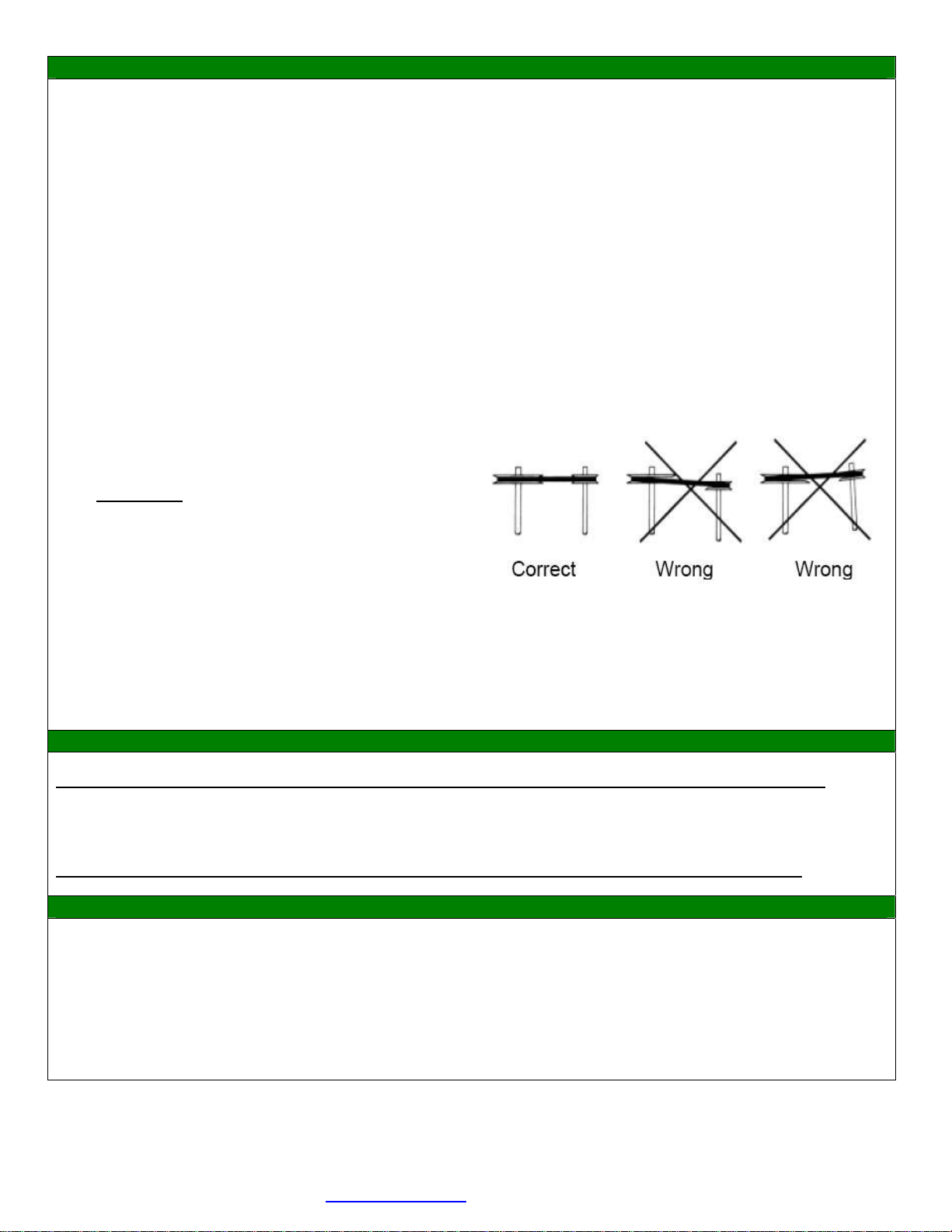
7. With the motor platform in its highest position install the V belt within the sheave grooves. Adjust the sheave on
the blower shaft to ensure proper pulley alignment (see figure 2) and secure in place. A straight edge across the
face of the driven pulley should be parallel to the belt once proper alignment has been achieved.
WARNING: Excessive belt tension is the most
frequent cause of bearing wear and resulting
noise. Proper belt tension is critical for quiet
efficient operation.
Fig. 2: Pulley Alignment
8. Loosen the four clamping bolts around the motor platform and slide the motor platform within the slotted rails to
adjust belt tension. Ideal belt tension is the lowest tension at which the belt will not slip during start up. As rule
of thumb suggests that ¾” of deflection mid span under medium finger pressure (2-3 lbs.) for every foot of span
is approximately proper belt tension. Tighten the motor platform clamping bolts once proper belt tension has
been achieved.
ELECTRICAL
WARNING: Ensure power supply is disconnected and locked out prior to making electrical connections.
Before connecting the motor to the electrical supply, check the electrical characteristics and wiring instructions as
indicated on the motor nameplate or as shown below. Complete electrical connections as indicated.
WARNING: A ground wire must be connected from the motor housing to a suitable electrical ground.
OPERATION
1. After electrical connections are completed, energize the unit momentarily and ensure that the rotation of the
wheel is correct. Apply full power.
2. With the air systems in full operation and all ducts and access panels attached, measure current input to the
motor and ensure that it is less than the rated full load motor amperage.
3. Proper adjustment to the belt tension is critical for quiet efficient operation.

Delhi Industries Inc. 523 James Street, Delhi, Ontario N4B 2Z3
Tel. (519) 582-2440 Fax. (519) 582-0581 www.delhi-industries.com
TABLE 1: DRIVE SELECTION BI-10 BI-12 BI-13 BI-15 BI-16 BI-18 BI-20
Based on 1725 RPM motor MOTOR FRAME
MOTOR BLOWER RPM 56/143 56/143T 182T 56/143T 182T 213T 56/143T 182T 213T 56/143T 182T 213T 56/143T 182T 213T 56/143T 182T 213T
PULLEY PULLEY RANGE 48 /145T 48 /145T /184T /145T /184T /215T /145T /184T /215T /145T /184T /215T /145T /184T /215T /145T /184T /215T
BKH140 252-384 4L470 -- 4L530 -- -- -- -- -- -- -- -- -- -- -- -- -- -- -- -- --
BKH110 327-500 4L400 B38 4L460 B43 -- B43 -- -- B43 -- -- B47 -- -- B47 -- -- B54 -- --
BKH80 468-714 4L330 B31 4L400 B37 -- B37 -- -- B37 -- -- B41 -- -- B41 -- -- B48 -- --
BKH60 655-1000 4L290 B27 4L360 B33 -- B33 -- -- B33 -- -- B37 -- -- B37 -- -- B45 -- --
BKH50 819-1250 4L270 B25 4L340 B32 -- B32 -- -- B32 -- -- B36 -- -- B36 -- -- B43 -- --
1VL34
BKH40 1024-1563 4L260 B24 4L330 B30 -- B30 -- -- B30 -- -- B34 -- -- B34 -- -- B42 -- --
BKH100 536-728 4L380 B36 4L440 B42 -- B42 -- -- B42 -- -- B45 -- -- B45 -- -- B53 -- --
BKH90 603-819 4L360 B34 4L430 B41 -- B41 -- -- B41 -- -- B44 -- -- B44 -- -- B52 -- --
BKH70 804-1092 4L320 B30 4L390 B37 -- B37 -- -- B37 -- -- B41 -- -- B41 -- -- B48 -- --
BKH60 965-1310 4L300 B28 4L370 B35 -- B35 -- -- B35 -- -- B39 -- -- B39 -- -- B44 -- --
BKH50 1207-1638 4L290 B26 4L350 B33 -- B33 -- -- B33 -- -- B37 -- -- B37 -- -- B45 -- --
1VL44
BKH40 1509-2049 4L270 B25 4L340 B32 -- B32 -- -- B32 -- -- B36 -- -- B36 -- -- B44 -- --
2B74SK 1599-1925 -- -- -- -- -- -- -- B42 -- -- B42 -- -- B45 -- -- B45 -- -- B53
2MVP70B84P 2B64SDS 1848-2266 -- -- -- -- -- -- -- B40 -- -- B40 -- -- B44 -- -- B44 -- -- B52
BI-22 BI-24 BI-27 BI-30 BI-33 BI-36
MOTOR FRAME
MOTOR BLOWER RPM
56/143T 182T 213T 56/143T 182T 213T 56/143
T 182T 213T
56/143
T 182T 213T
56/143
T 182T 213T 213T 254T 284T
PULLEY PULLEY RANGE
/145T /184T /215T /145T /184T /215T /145T /184T /215T /145T /184T /215T /145T /184T /215T /215T /256T /286T
BKH190 225-300 B72 -- -- B81 -- -- B81 -- -- -- -- -- -- -- -- -- -- --
BKH140 308-411 B61 -- -- B70 -- -- B70 -- -- -- -- -- -- -- -- -- -- --
BKH110 398-530 B55 -- -- B64 -- -- B64 -- -- -- -- -- -- -- -- -- -- --
BKH90 492-657 B51 -- -- B60 -- -- B60 -- -- -- -- -- -- -- -- -- -- --
BKH70 646-862 B47 -- -- B57 -- -- B57 -- -- -- -- -- -- -- -- -- -- --
1VL34
BKH50 940-1254 B43 -- -- B53 -- -- B53 -- -- -- -- -- -- -- -- -- -- --
BKH110 514-680 -- B54 -- -- B63 -- -- B63 -- -- -- -- -- -- -- -- -- --
BKH90 636-841 -- B50 -- -- B60 -- -- B60 -- -- -- -- -- -- -- -- -- --
BKH80 722-955 -- B48 -- -- B58 -- -- B59 -- -- -- -- -- -- -- -- -- --
BKH70 835-1105 -- B47 -- -- B56 -- -- B57 -- -- -- -- -- -- -- -- -- --
BKH60 990-1309 -- B44 -- -- B55 -- -- B55 -- -- -- -- -- -- -- -- -- --
1VP44
BKH50 1215-1607 -- B43 -- -- B53 -- -- B53* -- -- -- -- -- -- -- -- -- --
2B184SK 506-618 -- -- BX73(2) -- -- B81(2) -- -- B81(2) -- B89(2) B87(2) -- B89(2) B87(2) B88(2) -- --
2B124SK 751-918 -- -- BX59(2) -- -- B68(2) -- -- B68(2) -- B76(2) B75(2) -- B76(2) B75(2) B75(2) -- --
2B110SK 846-1034 -- -- BX57(2) -- -- B67(2) -- -- B67(2) -- B75(2) B73(2) -- B75(2) B73(2) B73(2)* -- --
2B86SK 1083-1323 -- -- BX52(2) -- -- B62(2) -- -- B62(2) -- B70(2)* B68(2)* -- B70(2)* B68(2)* -- -- --
2B64SDS 1455-1778 -- -- BX48(2) -- -- B58(2)* -- -- -- -- -- -- -- -- -- -- -- --
2VP71
-- -- -- -- -- -- -- -- -- -- -- -- -- -- -- -- -- --
25V2120SF 506-618 -- -- -- -- -- -- -- -- -- -- -- BX94(2) -- -- B94(2) B94(2) BX93(2) BX92(2)
2B154SK 751-918 -- -- B67(2) -- -- B76(2) -- -- B76(2) -- -- BX82(2) -- -- B82(2) B83(2) BX82(2) BX80(2)
2MVP70B84P
2B136SK 846-1034 -- -- B64(2) -- -- B73(2) -- -- B73(2) -- -- BX80(2) -- -- B80(2) B80(2)* BX79(2)* BX77(2)*
** Basic drive selections shown above. For more drive selection options, refer to the Delair Drive Selection program.
Delhi Industries Inc. 523 James Street, Delhi, Ontario N4B 2Z3
Tel. (519) 582-2440 Fax. (519) 582-0581 www.delhi-industries.com
MAINTENANCE
Ensure power supply is disconnected and locked out prior to performing maintenance
1. Inspect and tighten the wheel set screw after the first 50 to 100 hours of operation and periodically thereafter.
2. Follow the motor manufacturer’s instructions for motor lubrication. Remove any excess lubrication.
3. Drives:
A– Check belt tension and alignment, replace cracked or worn belts. If it is necessary to replace one
belt on a multiple belt drive, replace all the belts with a matched set.
B– Under normal conditions, no re-lubrication is the rule. The bearing lubricant cavity is 1/3-1/2 filled as
shipped from the factory. Never lubricate new bearings.
C – Tighten set-screws on sheaves, wheel and bearing locking collars.
4. Clean the blower wheel periodically. Material build up on the blades can cause wheel imbalance which, may
result in wheel or motor bearing failure.
5. Generally, bearings should be lubricated at six to twelve month intervals. Recommended lubricants are: a)
Imperial Oil – ESSO Beacon 325, or b) Shell Oil – Alvania Grease #3. A small amount of grease should be
added slowly when the shaft is rotating. Note: Over greasing may cause damage to the bearing. Avoid
rupturing the bearing seal.
6. To reinstall replacement ball bearings press the locking collar against the inner ring of the bearing and turn in the
direction of the shaft rotation until engaged. Insert a drift pin into the pin hole and tap lightly to set. Tighten set-
screw on locking collar firmly.
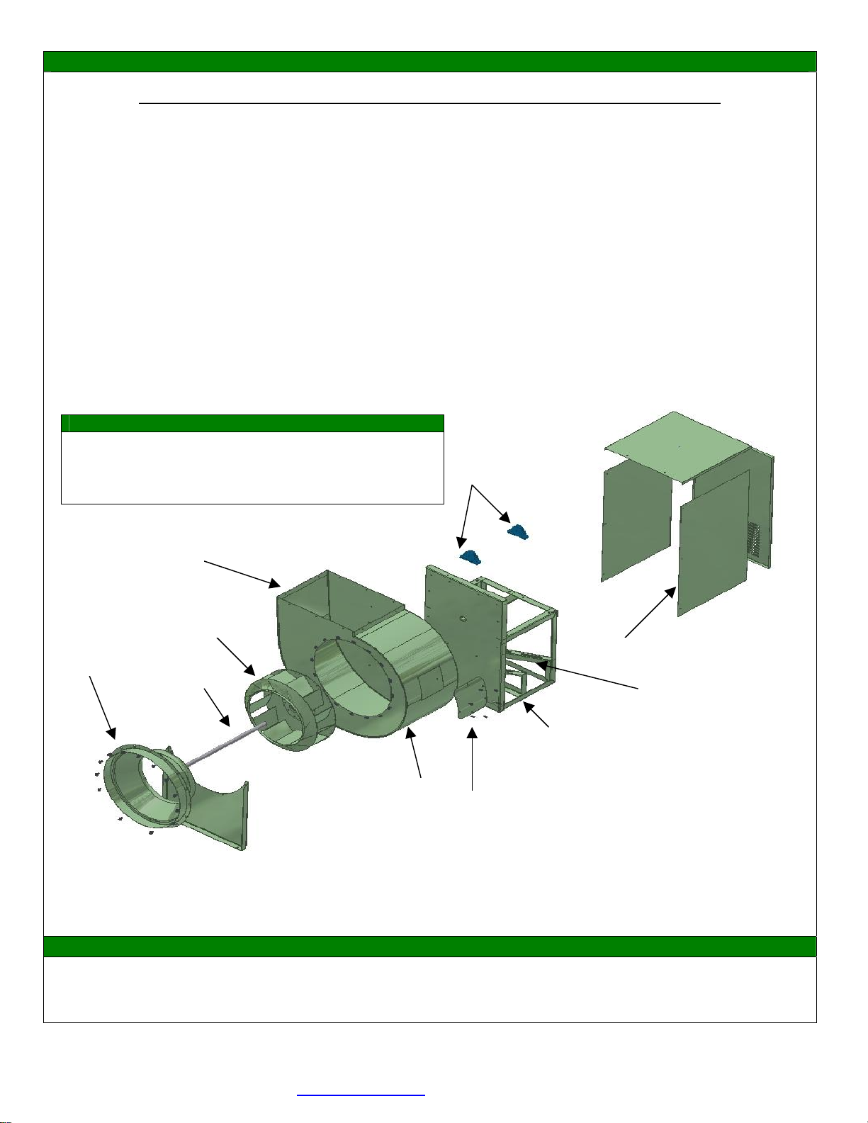
7. Should further service to the blower be necessary, refer to the exploded view illustration (Figure 3).
Figure 3: Exploded view
WARRANTY
Delhi Industries Inc. Air Moving Products are guaranteed for a period of one year against manufacturing defects in
material and workmanship when operating under normal conditions. Liability is limited to the replacement of defective
parts. Labour and transportation costs are not included.
1
4
3
10
6
9
7
5
8
2
PARTS LIST
1.INLET VENTURI C/W INLET RING
2.SHAFT (KEYWAYED BOTH ENDS)
3.BACKWARD INCLINE WHEEL
4.BLOWER HOUSING
5.MOTOR COMPARTMENT
6.PILLOW BLOCK BALL BEARINGS
7.MOTOR COMPARTMENT COVER
(3 REMOVABLE PANELS)
8.MOTOR PLATFORM
9.ACCESS DOOR (OPTIONAL, STD BI-RM)
10.DRAIN 2” DIA. EXT (OPTIONAL, STD BI-RM)
This manual suits for next models
26
Table of contents
Other Delhi Industries Blower manuals


