Desoutter Industrial Tools Sight 7.1 Instruction sheet

Printed Matter No. 6159925240
Issue No. 02
Date 06/2019
Page 1 / 28
Remote Display and Remote Display Module
Product Instructions
Model Part number
Sight 7.1” 6158132530
Sight 15.6” 6158132540
Sight module 6158132550
Download the latest version of this document at
www.desouttertools.com/info/6159925240
WARNING
Read all safety warnings and instructions
Failure to follow the safety warnings and instructions may result in
electric shock, fire and/or serious injury.
Save all warnings and instructions for future reference

2 / 28 06/2019
Table of Contents
Product Information ..............................................................................................................................3
General Information.........................................................................................................................3
Warranty...............................................................................................................................3
Website ................................................................................................................................3
Information about spare parts ..............................................................................................3
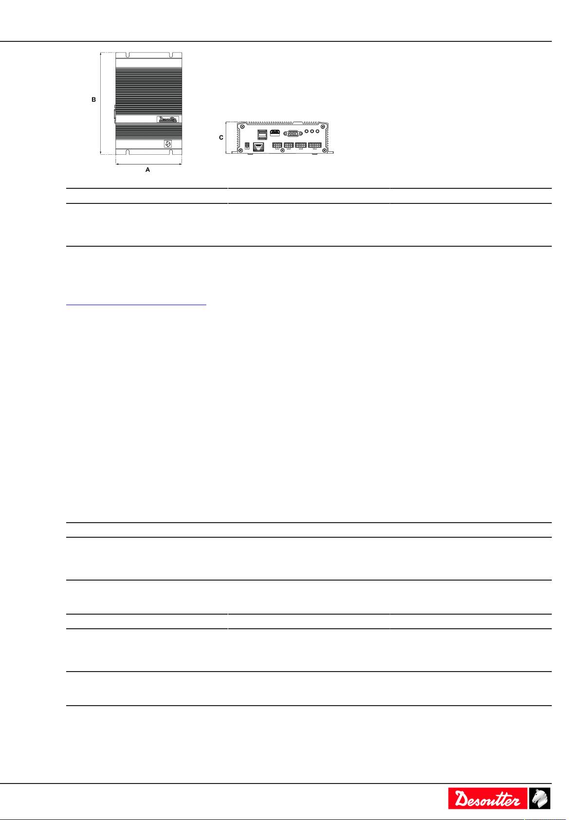
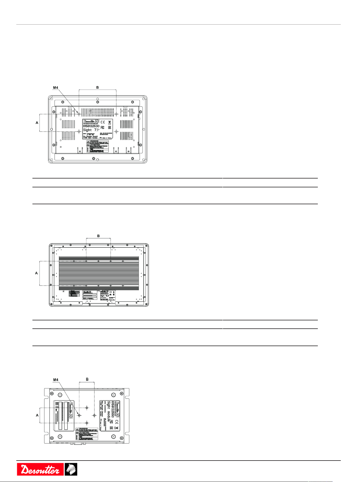
Dimensioning .......................................................................................................................3
CAD files ..............................................................................................................................5
Overview .........................................................................................................................................5
Product description ..............................................................................................................5
Technical data......................................................................................................................5
Accessories..........................................................................................................................6
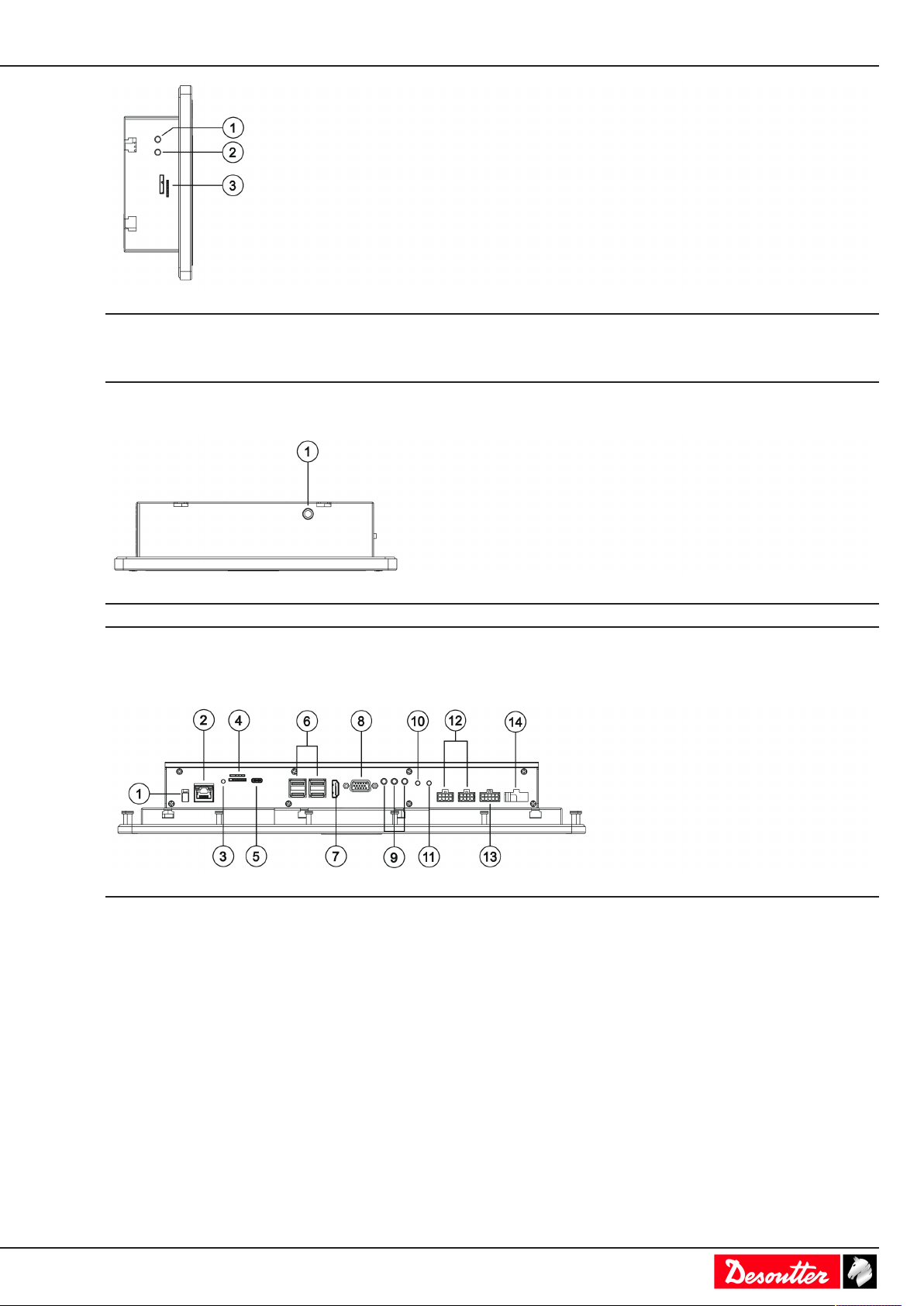
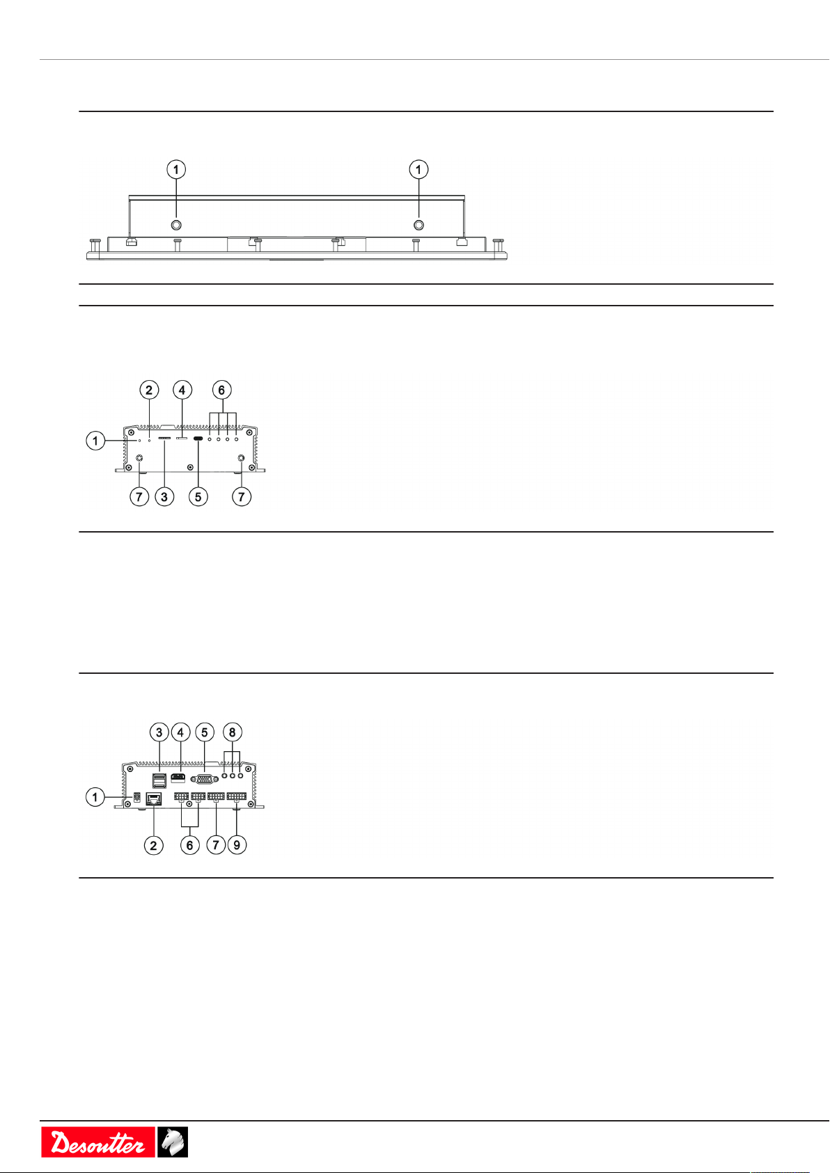
Description of connections ...................................................................................................6
Installation............................................................................................................................................10
Installation Instructions..................................................................................................................10
Installing the mounting support ..........................................................................................10
Connecting to SIGHT power supply and to CONNECT .....................................................11
Connecting to the PoE+ 30 W power injector and to CONNECT ......................................11
Connecting to PoE+ 13 W power injector / CONNECT / external display .........................12
Mounting the WI-FI antennas.............................................................................................13
Operation..............................................................................................................................................15
Configuration Instructions..............................................................................................................15
Initial setup .........................................................................................................................15
How to access to the control center ...................................................................................17
How to change the language .............................................................................................18
How to change the network configuration ..........................................................................18
How to remote control CONNECT .....................................................................................19
Operating Instructions ...................................................................................................................19
How to search for a specific page ......................................................................................19
How to swipe the pages .....................................................................................................20
How to select another Pset or Assembly Process .............................................................21
Service..................................................................................................................................................23
Maintenance instructions...............................................................................................................23
Cleaning .............................................................................................................................23
Maintenance program ........................................................................................................23
Read before maintenance..................................................................................................23
Checking before putting back into service .........................................................................23
How to save logs to a USB key .....................................................................................................23
Reset to factory .............................................................................................................................23
Upgrading the firmware .................................................................................................................24
Troubleshooting ..................................................................................................................................26
What if nothing is displayed...........................................................................................................26

EN Product Information
06/2019 3 / 28
Product Information
General Information
WARNING Risk of Property Damage or Severe Injury
Ensure that you read, understand and follow all instructions before operating the tool. Failure to follow all the
instructions may result in electric shock, fire, property damage and/or severe bodily injury.
►Read all Safety Information delivered together with the different parts of the system.
►Read all Product Instructions for installation, operation and maintenance of the different parts of the system.
►Read all locally legislated safety regulations regarding the system and parts thereof.
►Save all Safety Information and instructions for future reference.
Warranty
• Product warranty will expire 12 months after the product is first taken into use, but will in any case expire at the
latest 13 months after delivery.
• Normal wear and tear on parts is not included within the warranty.
• Normal wear and tear is that which requires a part change or other adjustment/overhaul during standard tools
maintenance typical for that period (expressed in time, operation hours or otherwise).
• The product warranty relies on the correct use, maintenance, and repair of the tool and its component parts.
• Damage to parts that occurs as a result of inadequate maintenance or performed by parties other than Desoutter
or their Certified Service Partners during the warranty period is not covered by the warranty.
• To avoid damage or destruction of tool parts, service the tool according to the recommended maintenance sched-
ules and follow the correct instructions.
• Warranty repairs are only performed in Desoutter workshops or by Certified Service Partners.
Desoutter offers extended warranty and state of the art preventive maintenance through its Tool Care contracts. For
further information contact your local Service representative.
For electrical motors:
• Warranty will only apply when the electric motor has not been opened.
Website
Information concerning our Products, Accessories, Spare Parts and Published Matters can be found on the Desoutter
website.
Please visit: www.desouttertools.com.
Information about spare parts
Exploded views and spare parts lists are available in Service Link at www.desouttertools.com.
Dimensioning
Sight 7.1"

Product Information EN
4 / 28 06/2019
mm in.
A 136 5.35
B 199 7.83
C 48 1.89
D 38 1.50
E 95 3.74
F 166 6.53
Sight 15.6"
mm in.
A 257 10.12
B 407 16.02
C 62 2.44
D 40 1.57
E 325 12.79
Sight module

EN Product Information
06/2019 5 / 28
mm in.
A 109 4.29
B 168 6.61
C 52 2.05
CAD files
For information about the dimensions of a product, see the Dimensional drawings archive:
http://resource-center.desouttertools
Overview
Product description
Sight 7.1" and Sight 15.6" are remote displays designed to display in real-time tightening results coming from
CONNECT.
They also can be used as remote accesses to CONNECT menu for on-line adjustments.
Sight module is a remote display module between CONNECT and an external remote display (HDMI, 1080p).
Technical data
Power supply
Sight 7.1", Sight 15.6" and Sight module can be powered by either the Desoutter SIGHT power supply or the Des-
outter PoE+ 30 W power injector.
Sight 7.1" and Sight module can also be powered by a PoE+ 13 W power injector (IEEE802.3af).
Power consumption
Model A
Sight 7.1" 3
Sight 15.6" 3
Sight module 3
Weight
Model Weight (kg) Weight (lb)
Sight 7.1" 0.98 2.16
Sight 15.6" 4.1 9.04
Sight module 0.72 1.59
Storage and use conditions
Storage temperature 0 to +50 °C (32 to +122 F)
Operating temperature 0 to +50 °C (32 to +122 F)
Storage humidity 90 % RH (non-condensing)
Operating humidity 90 % RH (non-condensing)

Product Information EN
6 / 28 06/2019
Altitude up to 2000 m (6562 feet)
Usable in Pollution degree 2 environment
IP54
Accessories
Optional accessories
SIGHT power supply 6158132620
PoE+ 30 W power injector (IEEE 802.3at) 6158132630
Use the following power cords to power supply (230 V AC) the above accessories.
Area Length Part number
Europe 2.5 m
8.2 ft
6159172010
USA 2.5 m
8.2 ft
6159172030
UK 2.5 m
8.2 ft
6159172020
China 2.5 m
8.2 ft
6159172060
37*75 VESA mounting support for Sight 7.1" 6158132880
100*100 VESA mounting support for Sight 15.6" 6158132580
Antenna kit for Sight 7.1" 6158133870
Antenna kit for Sight 15.6" and Sight Module 6158133860
Description of connections
Sight 7.1"
Bottom panel
1DC input connector
2Ethernet (LAN1)
3 GPIO - not used
4USB port
5 HDMI connector - not used
6 CANBus - not used
7 RS232 - not used
Left panel

EN Product Information
06/2019 7 / 28
1Reset button
2 S1 button - not used
3 Micro-SD card slot - not used
Top panel
1 Antenna connector
Sight 15.6"
Bottom panel
1DC input connector
2Ethernet (LAN1)
3 Micro-SD LED - not used
4 Micro-SD card slot - not used
5 Mini USB - not used
64 x USB ports
7 HDMI connector - not used
8 VGA connector - not used
9 Line out - not used
Line in - not used
Mic in - not used
10 S1 button - not used
11 Reset button
12 GPIO - not used

Product Information EN
8 / 28 06/2019
13 RS232 - not used
14 CANBus - not used
Top panel
1 Antenna connector
Sight module
Right panel
1Reset button
2 S1 button - not used
3 Micro-SIM card slot - not used
4 Micro-SD card slot - not used
5USB port
6 4 x LED - not used
7Antenna connector
Left panel
1DC input connector
2Ethernet (LAN1)
32 x USB ports
4HDMI connector
5 VGA connector - not used
6 2 x GPIO - not used
CANBus - not used
7 RS232 - not used
8 Line out - not used
Line in - not used
Mic in - not used

EN Product Information
06/2019 9 / 28
9 CANBus - not used

Installation EN
10 / 28 06/2019
Installation
Installation Instructions
Installing the mounting support
Sight 7.1"
Use the mounting support proposed as an optional accessory.
mm in.
A 35 1.38
B 75 2.95
Sight 15.6"
Use the mounting support proposed as an optional accessory.
mm in.
A 100 3.94
B 100 3.94
Sight module
Use a DIN rail bracket (not supplied).

EN Installation
06/2019 11 / 28
mm in.
A 30 1.18
B 30 1.18
Connecting to SIGHT power supply and to CONNECT
Sight 7"
Sight 15.6"
Sight module
1. Plug the power cord to SIGHT power supply.
2. Plug the connection cable to the DC input of Sight.
3. Plug the power cord to the mains.
To communicate with CONNECT, use the WI-FI network or plug an Ethernet cable to the Ethernet (LAN1) of
Sight and to any available Ethernet port of CONNECT.
Connecting to the PoE+ 30 W power injector and to CONNECT
Valid for all models of Sight.
For example: Sight 15.6"

Installation EN
12 / 28 06/2019
1. Plug the power cord to the power injector.
2. Plug an Ethernet cable from OUT to the Ethernet (LAN1) of Sight.
3. Plug the power cord to the mains.
4. Plug an Ethernet cable from IN to any available Ethernet port of CONNECT.
NOTICE Do not use DC power supply when the device is already powered by a PoE power adaptor .
Connecting to PoE+ 13 W power injector / CONNECT / external display
Sight 7"
1. Plug the power cord to the power injector.
2. Plug an Ethernet cable from OUT to the Ethernet (LAN1) of Sight.
3. Plug the power cord to the mains.
4. Plug an Ethernet cable from IN to any available Ethernet port of CONNECT.
NOTICE Do not use DC power supply when the device is already powered by a PoE power adaptor .
Sight module

EN Installation
06/2019 13 / 28
1. Plug the power cord to the power injector.
2. Plug an Ethernet cable from OUT to the Ethernet (LAN1) of Sight.
3. Plug the power cord to the mains.
4. Plug an Ethernet cable from IN to any available Ethernet port of CONNECT.
5. Plug the display to the HDMI port.
6. Plug the display to the mains.
NOTICE Do not use DC power supply when the device is already powered by a PoE power adaptor .
Mounting the WI-FI antennas
Always remove the antennas before moving the product.
Sight 7.1"
Sight 15.6"

Installation EN
14 / 28 06/2019
Sight module

EN Operation
06/2019 15 / 28
Operation
Configuration Instructions
Initial setup
Powering on
CONNECT must be up and running.
There is no ON/OFF switch.
The software starts as soon as the system is powered ON.
How to select the language
Click Choose language.
Available languages are as follows:
• English
• French
• Spanish
• German
• Swedish
• Italian
• Japanese

Operation EN
16 / 28 06/2019
• Chinese
• Russian
• Portuguese (Portugal)
• Dutch
• Portuguese (Brazil)
• Korean
• Farsi
• Czech
• Turkish
Scroll through the list and select the desired language. Changes are automatically applied.
How to connect SIGHT to a WI-FI network
Click Getting started > Wireless.
The list of available WI-FI networks is displayed.
Select a WI-FI network in the list.
Enter the security key (password) of the network configuration you want to connect to.
You will be then asked to give Sight an IP address, subnet mask, etc...
Refer to the chapter How to connect SIGHT to an Ethernet network [Page16] in this manual.
How to connect SIGHT to an Ethernet network
Click Getting started > Ethernet.
If you want to have Sight set up in Static mode, click Default to fill in the screen with the default values.
Enter the correct values of IP address, subnet mask and gateway.
The MAC address will be automatically displayed.
Click Apply.

EN Operation
06/2019 17 / 28
If you want to have Sight set up in DHCP mode, tick the box on the upper left side.
Click Apply.
How to connect SIGHT to a system
Check you have first connected SIGHT to a WI-FI or Ethernet network.
Click Scan to get the list of the systems available.
Or type the IP address of the system and click the button "Connect".
Select the system.
Go to the column Action and click this symbol.
In the next screen, click Auto-configuration.
The green icon on the top right indicates the communication is established with the system.
The name of the system is displayed on the top.
In the example above, the name of the system is CONNECT-W.
The page displayed shows 2 tiles.
How to access to the control center
Go to the main screen.
Click this button to open the control center.

Operation EN
18 / 28 06/2019
Click this icon to access to the configuration of Sight.
Click this icon to access to the configuration of CONNECT.
How to change the language
Open the control center.
Click this icon to access to the configuration of Sight.
Click this icon.
Click System > User interface > Language.
Select the desired language. Changes are automatically applied.
Click this icon on the top left up to the overview.
How to change the network configuration
Open the control center.
Click this icon to access to the configuration of Sight.
Click this icon.
Click System > Peripherals > Networks > Ethernet.

EN Operation
06/2019 19 / 28
Do the modifications.
Click Apply.
Click this icon on the top left up to quit.
How to remote control CONNECT
Open the control center.
Click this icon to access to the configuration of CONNECT.
Results
Configuration
Maintenance
Change the settings as you would do in CONNECT.
Refer to the Product Instructions of CONNECT available at https://www.desouttertools.com/resource-centre.
Operating Instructions
How to search for a specific page
Click the name of the system on the top.
For example: CONNECT-W
Scroll the list and click a page to open it.

Operation EN
20 / 28 06/2019
For example:
How to swipe the pages
Open a page.
For example:
Swipe this arrow on the right of the screen to display the next page.
The intermediate page is displayed.
Swipe this arrow on the right of the screen to display the next page.
The last page is displayed.
This manual suits for next models
5
Table of contents
Popular Monitor manuals by other brands

Samsung
Samsung SyncMaster 206BW user manual

Pioneer
Pioneer Elite PureVision PRO 1140HD operating instructions

Runco
Runco PLASMAWALL XP-65DHD Owner's operating manual

Westinghouse
Westinghouse LVM-37w3 user manual

Hansol
Hansol 19Inch (Viewable size 18 ) High Resolution Color Monitor... user manual

Farenheit
Farenheit 5.8" TFT LCD Wide color monitor user manual