DETEWE M100-ADSL User manual

1
Installationsanleitung M100-ADSL Interface DSL Modem
M100-ADSL Interface
DSL Modem
Die Schnittstellenkarte M100-ADSL
Interface DSL Modem ist ein inte-
griertes DSL Modem. Damit kann die
OpenCom 100 (OpenCom 130/150) an
einem DSL-Anschluss betrieben wer-
den, ohne dass ein externes DSL-Mo-
dem benötigt wird. Das M100-ADSL
Interface DSL Modem unterstützt die
U-R2-Schnittstelle nach 1 TR 112.
Diese Anleitung setzt voraus, dass der
DSL-Anschluss bereitgestellt wurde
und der DSL-Splitter bereits montiert
ist.
Lieferumfang
■1 Schnittstellenkarte M100-ADSL
Interface DSL Modem
■1 Kabel (RJ45) zum Anschluss der
Schnittstellenkarte an den Splitter
■1 Satz Kabelbinder zur Befestigung
des Anschlusskabels
■1 Installationsanleitung
Installation
Die Schnittstellenkarte darf nur von
Fachpersonal eingebaut werden!
Zur Installation der Baugruppen der
OpenCom 100 und der Schnitt-
stellenkarten beachten Sie bitte auch
die Informationen in der Bedienungs-
anleitung „OpenCom 100 Montage
und Inbetriebnahme“.
So gehen Sie vor
GEFAHR! Gefährliche Span-
nungen innerhalb des Geräts.
1. Schalten Sie die OpenCom 100 aus.
Öffnen Sie den Gehäusedeckel.
2. Nehmen Sie die Schnittstellen-
karte aus der Transportver-
packung. Überprüfen Sie, ob es
sich um den gewünschten Karten-
typ handelt. Sie finden dazu auf
dem Steckverbinder ein Etikett mit
der Typ-Bezeichnung.
VORSICHT! Statische Auf-
ladungen können elektronische
Bauteile beschädigen. Beachten
Sie die Handhabungsvorschriften
für elektrostatisch gefährdete
Bauelemente!
2M100-ADSL Interface DSL Modem Installationsanleitung
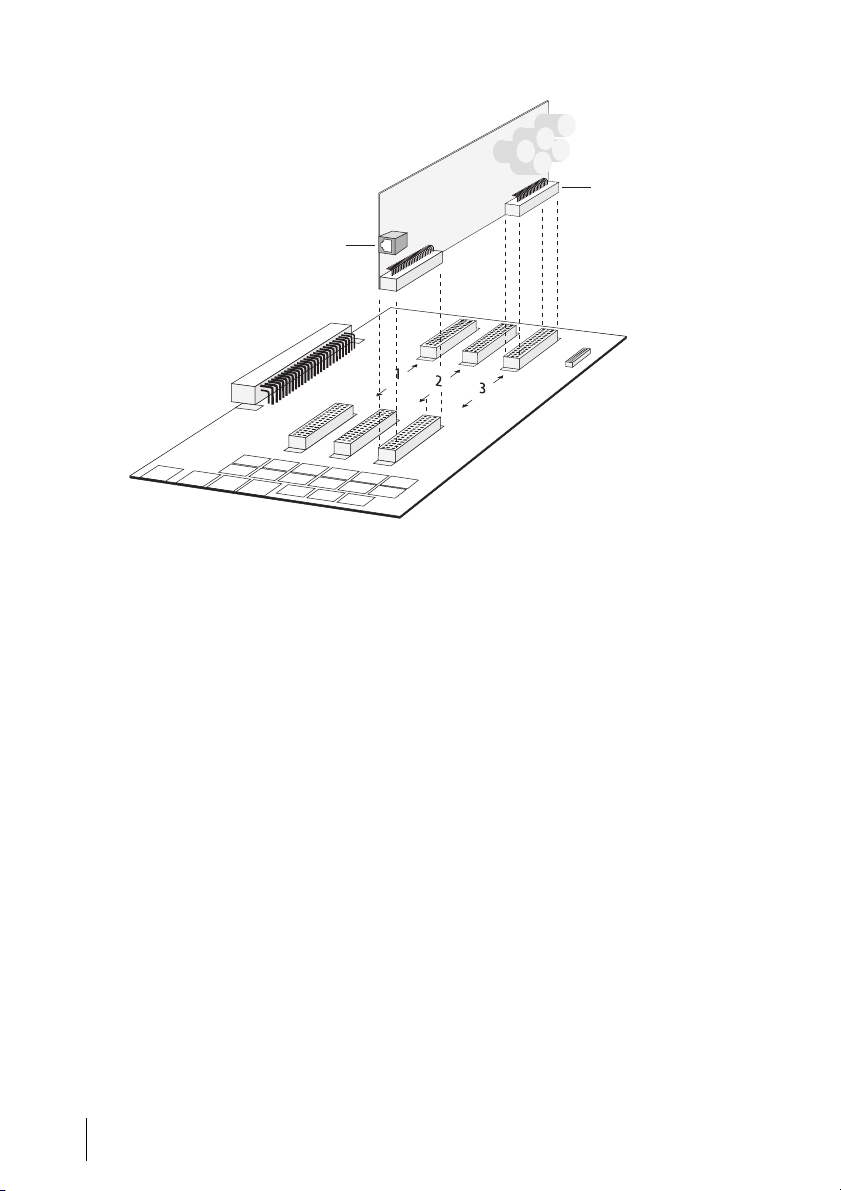
Schnittstellenkarte installieren (hier: OpenCom130)
3. Stecken Sie die Schnittstellenkarte
vorsichtig in den Steckplatz:
– OpenCom 130: Steckplatz Nr. 3.
Der Betrieb in Steckplatz 1 oder 2
ist nicht möglich.
– OpenCom 150: Steckplatz Nr. 4
oder Nr. 5.
Die Bauteileseite muss nach rechts
zeigen. Achten Sie auf sicheren Sitz
der Steckverbindung.
4. Verbinden Sie die Schnittstellen-
karte mit dem DSL-Splitter. Be-
nutzen Sie hierzu das mitgelieferte
Anschlusskabel. Stecken Sie dieses
in die RJ45-Buchse auf der Schnitt-
stellenkarte, das andere Ende in
die RJ45-Buchse des DSL-Splitters.
Achtung! Um den Zug auf die RJ45-
Buchse der Schnittstellenkarte zu ver-
ringern, sollten Sie das Anschlusskabel
nicht lose aus dem Gehäuse führen,
sondern am Gehäuse befestigen (z.B.
mit dem gelieferten Kabelbinder an
einer der Aussparungen / Rippen am
unteren Gehäuserand).
5. Schließen Sie den Gehäusedeckel.
Schalten Sie die OpenCom 100 ein.
RJ45-Buchse
Typ-Bezeichnung
3
Installationsanleitung M100-ADSL Interface DSL Modem
LEDs auf der Schnittstellenkarte
LED 1 ist nach einem Reset für ca. 5 sec
an (Eigentest), danach für ca. 10 sec
aus (Systeminitialisierung).
Das Modem ist betriebsbereit, wenn
LED 1 dauerhaft blinkt (250 ms an /
250 ms aus).
LED 2 kennzeichnet die Verbindung
zwischen dem Switch auf der Bau-
gruppe und dem Modem (LED leuchtet
dauerhaft). LED 2 ist kurzfristig aus, so-
lange LED 5 flackert.
LED 3 ist aus, wenn das Modem „down“
ist. LED 3 blinkt im Rhythmus 250 ms
an / 250 ms aus, wenn das Modem „in
activation“ ist. Nach ca. 2,25 sec wird
der Status „in activation“ für ca. 1 sec
durch den Status „down“ ersetzt. Im
Status „showtime“ (= synchronisiert)
ist LED 3 dauerhaft an.
LED 4 ist aus, wenn kein ADSL-Daten-
transfer stattfindet. LED 4 flackert bei
Datenverkehr abhängig von der Trans-
ferrate.
LED 5 ist aus, wenn kein Ethernet-
Transfer stattfindet. LED 5 flackert bei
Ethernet-Transfer (in diesem Fall ist
LED 2 aus).
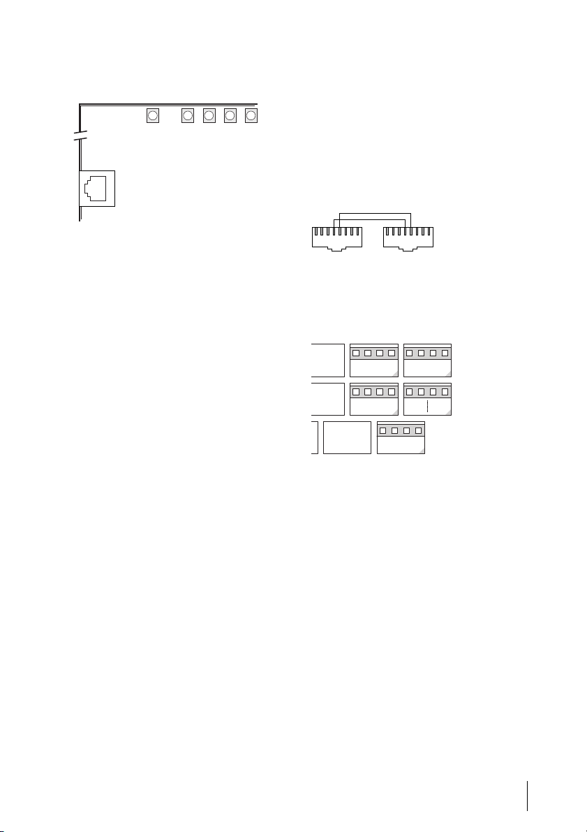
Anschlussbelegungen
Alternativ zur Verkabelung über die
RJ45-Buchsen können Sie die Verbin-
dung von der Schnittstellenkarte zum
Splitter auch über Druckklemmen
(Steckplatz Nr. 3) führen.
Kabelbelegung an den Steckern des
RJ45-Kabels
Anschluss der Schnittstellenkarte an
Druckklemmen (hier: OpenCom 130)
1:LED-Ready
2:LED-Ethernet-Link
3:LED-ADSL-Showtime
4:LED-ADSL-Receive
5:LED-Ethernet-Transfer
15432
DSL Splitter
Pin 4:U-R2 a Pin 5:U-R2 b
12345678 12345678
DSL Modem
Steckplatz 3
a
U-R2
b

4M100-ADSL Interface DSL Modem Installationsanleitung
Konfiguration
Nachdem Sie die OpenCom 100 wieder
in Betrieb genommen haben, kon-
figurieren Sie das DSL Modem im
Konfigurator der Web-Konsole. Beach-
ten Sie dabei auch die Informationen in
der Online-Hilfe der OpenCom 100.
So gehen Sie vor
1. Melden Sie sich im Konfigurator
als Benutzer mit Administrations-
rechten an.
Hinweis: Für die Konfiguration des
DSL Modems über die Web-Konsole der
OpenCom 100 ist eine Firmware Version
5.1 oder höher erforderlich. Spielen Sie
ggf. zuerst im Menü SYS Konfigura-
tion: Firmware eine neue Version ein.
Laden Sie danach im Menü SYS Konfi-
guration: Komponenten die aktuelle
Version der Online-Hilfe.
2. Öffnen Sie das Menü
PBX Konfiguration: Anschlüsse:
Steckplätze. In der Tabellenspalte
gesteckt wird für den gewählten
Steckplatz der Kartentyp DSL Mo-
dem angegeben.
3. Um das DSL Modem in Betrieb zu
nehmen, müssen Sie es konfigurie-
ren. Klicken Sie dazu den Tabellen-
eintrag Steckplatz an.
Der Dialog PBX Konfiguration -
Anschlüsse - Steckplatz - Ändern
wird geöffnet.
4. Wählen Sie in der Auswahlliste
konfiguriert den Kartentyp DSL
Modem. Bestätigen Sie die Aus-
wahl mit Übernehmen.
5. Um über das DSL Modem Verbin-
dungen ins Internet aufzubauen,
müssen Sie eine geeignete ISP-
Verbindung einrichten. Öffnen Sie
das Menü NET Konfiguration:
Verbindungen: ISP. Klicken Sie auf
der Statusseite ISP - Provider auf
den Button Neu. Der Dialog ISP -
Provider - Neu wird geöffnet.
6. Wählen Sie eine der folgenden
Verbindungsarten: T-Online T-DSL
(PPPoE), T-Business T-DSL
(PPPoE), DSL (PPPoE). Vervollstän-
digen Sie die Daten in den nun ein-
geblendeten Formularfeldern (Ein-
zelheiten siehe Online-Hilfe).
Bestätigen Sie die Eingaben mit
Übernehmen.
Hinweis: Wenn bereits ein anderes
xDSL-Modem mittels PPPoE im gleichen
LAN betrieben wird, kann dies zu Kon-
flikten beim Aufbau von Internet-
Verbindungen führen (Verwechlungs-
gefahr). Entfernen Sie das andere DSL-
Modem aus dem LAN. Deaktivieren Sie
die entsprechenden Modemtreiber auf
den Rechnern, die bisher auf dieses
Modem zugegriffen haben.

5
Installationsanleitung M100-ADSL Interface DSL Modem
Statusabfrage
Der aktuelle Status des DSL Modems
wird in der Web-Applikation ISP auf
der Web-Konsole angezeigt.
Update der Modem-Firmware
Falls eine neuere Version der Modem-
Firmware zur Verfügung gestellt wird,
können Sie diese im Menü SYS Konfi-
guration: Komponenten einspielen.
Versionsabfrage
Die aktuelle Version der Firmware
der OpenCom 100 und des DSL
Modems werden im Menü Systeminfo:
Versionen angezeigt.

6M100-ADSL Interface DSL Modem Installationsanleitung
DeTeWe Systems GmbH
Zeughofstraße 1, D-10997 Berlin
WWW: http://www.detewe.de/
Stand 06.2005
Änderungen vorbehalten

7
Installation Guide M100-ADSL Interface DSL Modem
M100-ADSL Interface
DSL Modem
The M100-ADSL interface DSL
modem is an integrated DSL modem.
It enables you to operate the
OpenCom 100 (OpenCom 130/150) on
a DSL access without having to acquire
an external DSL modem. The M100-
ADSL interface DSL modem supports
the U-R2 interface in accordance with
1 TR 112.
This user guide assumes that you al-
ready have a DSL access and that the
splitter has been installed.
Scope of Delivery
■One M100-ADSL interface DSL
modem interface card
■One RJ45 cable for connecting the
interface card to the splitter
■One set of cable ties for securing
the connection cable
■One installation guide.
Installation
Installation of the interface card
should only be performed by spe-
cially trained personnel.
For information on installing the
OpenCom 100 modules and interfaces,
please refer to the chapter entitled
“Mounting and Commissioning” in the
OpenCom 100 user guide.
Proceed as follows:
DANGER! This device contains
hazardous voltages.
1. Turn off the OpenCom 100.
Open the housing cover.
2. Remove the interface card from its
transport packaging. Check that it
is the correct type of card. (There is
a sticker with the type name on the
connector.)
CAUTION! Static charges can
damage electronic components.
Pay attention to the regulations re-
garding the installation of electro-
statically sensitive components.

8M100-ADSL Interface DSL Modem Installation Guide
Installation of the Interface Card (this figure: OpenCom130)
3. Carefully insert the interface card
in the slot:
– OpenCom 130: slot no. 3.
– OpenCom 150: slot no. 3,no. 4
or no. 5.
The component side must face to
the right. Ensure that the card is
fitted securely.
4. Connect the interface card to the
DSL splitter with the connector
cable supplied. Plug one end of the
cable into the RJ45 socket on the
interface card, and the other end
into the RJ45 socket on the DSL
splitter.
Please note: In order to reduce the
tension on the RJ45 socket, you should
never lead the connection cable loosely
out of the housing. Always secure the
cable to the housing, e.g. by using the
cable ties supplied to fasten the cable to
one of the recesses or ribs running along
the lower edge of the housing.
5. Close the housing cover.
Turn on the OpenCom 100.
RJ45 jack
Type (name) of
the interface card
9
Installation Guide M100-ADSL Interface DSL Modem
The LEDs on the Interface Card
LED 1 is illuminated for approx.
five seconds after a reset (self test), and
is then extinguished for approx.
ten seconds (system initialisation). The
modem is ready for operation when
LED 1 flashes continuously in 250-ms
cycles).
LED 2 indicates that there is a connec-
tion between the switch on the mod-
ule and the modem (the LED is illumi-
nated continuously). LED 2 is
temporarily extinguished when LED 5
flickers, i.e. during a data transfer via
Ethernet.
LED 3 is off when the modem is down.
LED 3 flashes on and off in 250-ms
cycles when the modem is in active.
After approx. 2.25 seconds, the modem
goes from the active state to the
“down” state for approx. one second. In
the “showtime” state (= synchronised),
LED 3 is illuminated continuously.
LED 4 is off as long as there is no data
transfer via ADSL. During data transfer
via ADSL, LED 4 flickers at a speed de-
pending on the data transfer rate.
LED 5 is off as long as there is no data
transfer via Ethernet. During data
transfer via Ethernet, LED 5 flickers (in
this case, LED 2 is off).
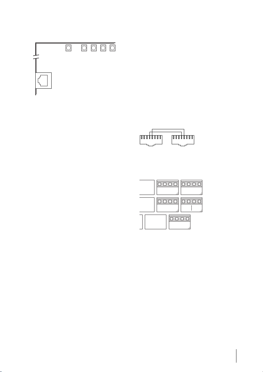
Pin outs
As an alternative to using the RJ45
sockets to connect the interface card to
the splitter, you can use the pressure
terminals (slot no. 3).
The RJ45 cable pin outs
Connection of an interface card to
pressure terminals (this figure:
OpenCom 130)
1:LED Ready
2:LED Ethernet Link
3:LED ADSL Showtime
4:LED ADSL Receive
5:LED Ethernet Transfer
15432
DSL Splitter
Pin 4:U-R2 a Pin 5:U-R2 b
12345678 12345678
DSL Modem
Slot 3
a
U-R2
b

10 M100-ADSL Interface DSL Modem Installation Guide
Configuration
When you have restarted the
OpenCom 100, you use the
Configurator in the Web console to
configure the DSL modem. Please also
refer to the information in the
OpenCom 100 online help.
Proceed as follows:
1. Log in to the Configurator as a
user with administrator rights.
Note: In order to configure the DSL
modem via the OpenCom 100 Web con-
sole, you require Version 5.1 or higher of
the firmware. If necessary, first use the
SYS Configuration: Firmware menu to
load the new firmware. Then use the
SYS Configuration: Components
menu to load the current version of the
online help.
2. Open the PBX Configuration:
Ports: Slots menu. The card type
DSL modem appears in the in-
serted column of the table for the
selected Slot.
3. In order to begin operating the DSL
modem, you must first configure it.
To do this, you click on the entry
Slot in the table.
The PBX Configuration - Ports -
Slot - Change dialogue opens.
4. You then select the card type DSL
modem from the Configured list,
and confirm your selection by
clicking on Apply.
5. In order to establish connections to
the Internet via the DSL modem
you must configure a suitable ISP
connection. To do this, open the
NET Configuration: Connections:
ISP menu. Click on theNew button
on the ISP - Provider status page.
The ISP - Provider - New dialogue
opens.
6. Select one of the following types of
connection: T-Online T-DSL
(PPPoE), T-Business T-DSL
(PPPoE) or DSL (PPPoE). Complete
the data in the input fields that
now open (for details, please see
the online help). To confirm your
input, click on Apply.
Note: If another xDSL modem is
already being operated via PPPoE in
the same LAN, conflicts can arise when
connections to the Internet are estab-
lished (there is a risk of confusion).
Remove the other DSL modem from the
LAN, and deactivate the corresponding
modem drivers on all PCs that used to
access this modem.

11
Installation Guide M100-ADSL Interface DSL Modem
Status Query
The current status of the DSL modem is
displayed in the ISP Web application
on the Web console.
Updating the Modem Firmware
Whenever a newer version of the
modem firmware becomes available,
you can use the SYS Configuration:
Components to load it.
Version Query
The current versions of the
OpenCom 100 and the DSL modem
firmware are displayed in the System
info: Versions menu.

12 M100-ADSL Interface DSL Modem Installation Guide
DeTeWe Systems GmbH
Zeughofstraße 1, D-10997 Berlin
WWW: http://www.detewe.de/
As of June 2005
Subject to changes
Other manuals for M100-ADSL
1
Table of contents
Languages:
Other DETEWE Modem manuals

Popular Modem manuals by other brands


Multitech
Multitech MultiModem MT3334ZDX owner's manual

Multitech
Multitech MultiModemII MT5600BR-V92 user guide

Multitech
Multitech MultiModem MT2834MR6 Product update

Multitech
Multitech MultiModem MTCBA-G-UF1 user guide

Multitech
Multitech MultiModem MTCBA-G-UF1 user guide

AirLive
AirLive ARM-201 user manual


