Guidelines and operation of this devi e
While the various MixDesk mixers are similar to use and built in much the same way, some of the following
information and images may not apply to your model. Be sure to check whether certain features are present
on your model by comparing it to the information shown in this user manual for best results.
Mono hannels
A mono channel on a PA mixer is normally used for standard microphone signals. They re occasionally used
for mono line signals too, but stereo line signals are normally used unless this is not possible for some
reason.
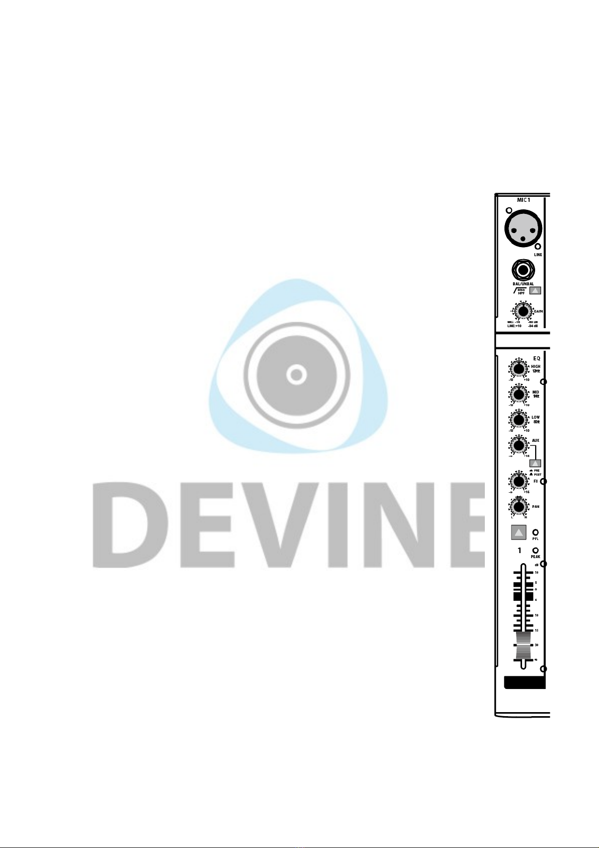
A complete mono channel with all its controls is called a channel strip. Depending on the model
of your mixer, you ll have multiple mono channels available with the following functions:
Mi : microphone input with a 3-pin XLR connector.
Line in: to connect a line signal to a mono channel use the TRS jack connector. A balanced or
unbalanced signal can be used.
HPF: for certain signal sources, such as vocal microphones, it can be undesirable for
frequencies below 80 Hz to be processed. By activating the HPF (high-pass filter), all
frequencies below 80 Hz received from the signal source will be dampened by 18 dB. In visual
terms, this would be seen as a descending line with less and less of the signal remaining the
lower the frequencies go.
Gain: with the gain knob, the amplification of the channel s input signal can be adjusted in order
to realise its full dynamic potential and prevent distortion. When connecting to an input, the gain
knob should be turned all the way down (as far to the left as possible). Once connected, the
input signal can be amplified by slowly turning the gain knob up again (to the right) until the
CLIP level is reached. This is the point that the signal has its fullest dynamic range without
distortion. If this level is surpassed, the signal will start to clip and distortion will occur. This will
also be seen on the PEAK LED indicator and when this occurs, you should turn the gain knob
down again until the signal is no longer clipping. It s best turn the gain knob down a little further
too to allow some extra space for any dynamic differences in the signal that may occur. This
extra space is known as headroom. With practice you will become more familiar with the best
settings for certain situations. The signal level from microphones used by novice speakers or
vocalists may fluctuate widely and you should consider turning down the gain knob a little more
to compensate for any peaks that may occur in order to avoid potential problems with clipping.
EQ: the mono channels all have a 3-band EQ giving you control over the balance between the
low (80 Hz), mid (2.5 kHz) and treble (12 kHz) frequencies. Each one can be cut or boosted with
values between -15 and +15 dB. This can be handy for accentuating the high tones in vocals,
for instance.
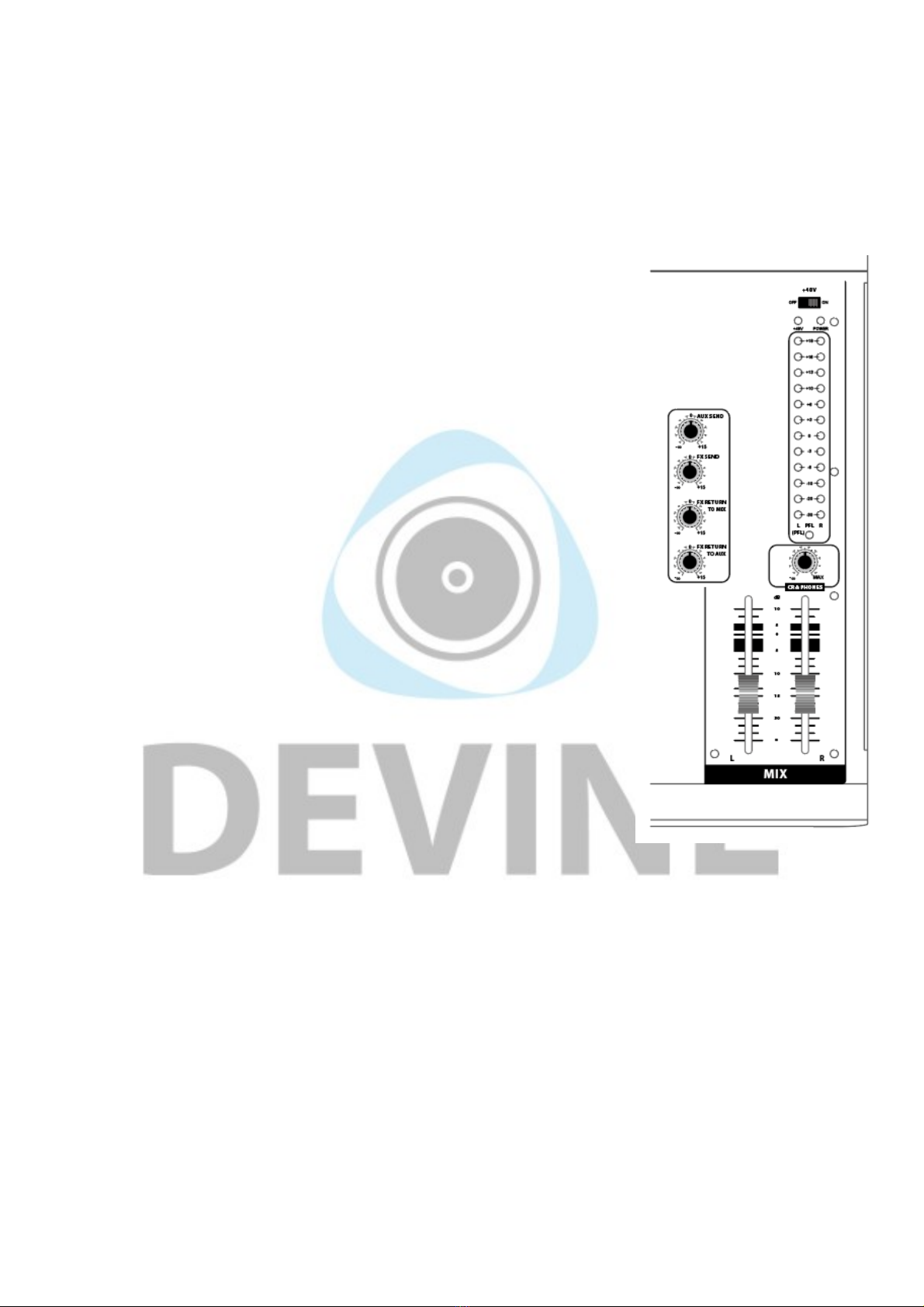
Aux: with the Aux knob, you can determine how much of the input signal is sent to the Aux
Send output and with the PRE/POST control, you can determine whether the signal is sent to
the Aux Send output before (pre) or after (post) the fader.
FX: some mixers have a built-in effects module and other mixers have the possibility to connect
external effects. With the FX knob, the effect level on the channel can be adjusted. This can be
handy for adding a touch of reverb to a vocalist s performance, for instance. More information
about the effects function can be found later on in this manual.
The more the FX knob is turned up (to the right), the more of the channel s sound will be sent to
the effects module or output. When it s set to 0 dB, it will be sent optimally, but without any
amplification. Turing it up (to the right) will amplify it by up to a maximum 15 dB. Note that this
may cause distortion in the signal. When the knob is turned all the way down (to the left),
nothing will be sent from the channel to the effects module.
The information in this user manual is subject to change at any time without notice.
Version:
1.0
Date of creation and author's initials:04-12-2018 RV Revision date and author's initials: -