DEWESOFT DS-CAM-88c Product manual

DS-CAM-88c / DS-CAM-120c
/ DS-CAM-175c / DS-CAM-320c
TECHNICAL REFERENCE MANUAL
DS-CAM-88c / DS-CAM-120c/ DS-CAM 175c/ DS-CAM 320c - V20-1
1

DS-CAM-88c / DS-CAM-120c / DS-CAM-175c / DS-CAM-320c
TECHNICAL REFERENCE MANUAL
1. Table of contents
1. Table of contents 2
2. About this document 4
2.1. Legend 4
3. Key features 5
3.1. System Requirements 5
4. Technical data 6
4.1. Specifications 6
4.2. Scope of supply 9
4.2.1. DS-CAM camera versions 9
4.2.2. Accessories 9
4.2.3. Optional 10
4.3. Connections 12
4.3.1. Power/Trigger connector pinout 13
4.3.2. SIRIUS® connection example 14
4.2.4. Connecting multiple cameras 15
4.2.5. Connections Overview 17
4.3. Benchmarks 19
5. Installation 20
5.1. DewesoftX® full installer 20
5.2. Manual installation 22
5.2.1. Required files 22
5.2.1. Step-by-step instruction 23
6. Troubleshooting guide 30
7. Warranty information 34
7.1. Calibration 34
7.2. Support 34
7.3. Service/repair 34
7.4. Restricted Rights 34
7.5. Printing History 35
7.6. Copyright 35
7.7. Trademarks 35
8. Safety instructions 36
8.1. Safety symbols in the manual 36
8.2. General Safety Instructions 36
8.2.1. Environmental Considerations 36
8.2.2. Product End-of-Life Handling 36
8.2.3. System and Components Recycling 36
8.2.4. General safety and hazard warnings for all Dewesoft systems 37
DS-CAM-88c / DS-CAM-120c / DS-CAM-175c / DS-CAM-320c DS-V20-2 2/40

DS-CAM-88c / DS-CAM-120c / DS-CAM-175c / DS-CAM-320c
TECHNICAL REFERENCE MANUAL
2. About this document
2.1. Legend
The following symbols and formats will be used throughout the document.
Important
It gives you important information about the subject.
Please read carefully!
Hint
It gives you a hint or provides additional information about a subject.
Example
Gives you an example of a specific subject.
DS-CAM-88c / DS-CAM-120c / DS-CAM-175c / DS-CAM-320c DS-V20-2 4/40

DS-CAM-88c / DS-CAM-120c / DS-CAM-175c / DS-CAM-320c
TECHNICAL REFERENCE MANUAL
3. Key features
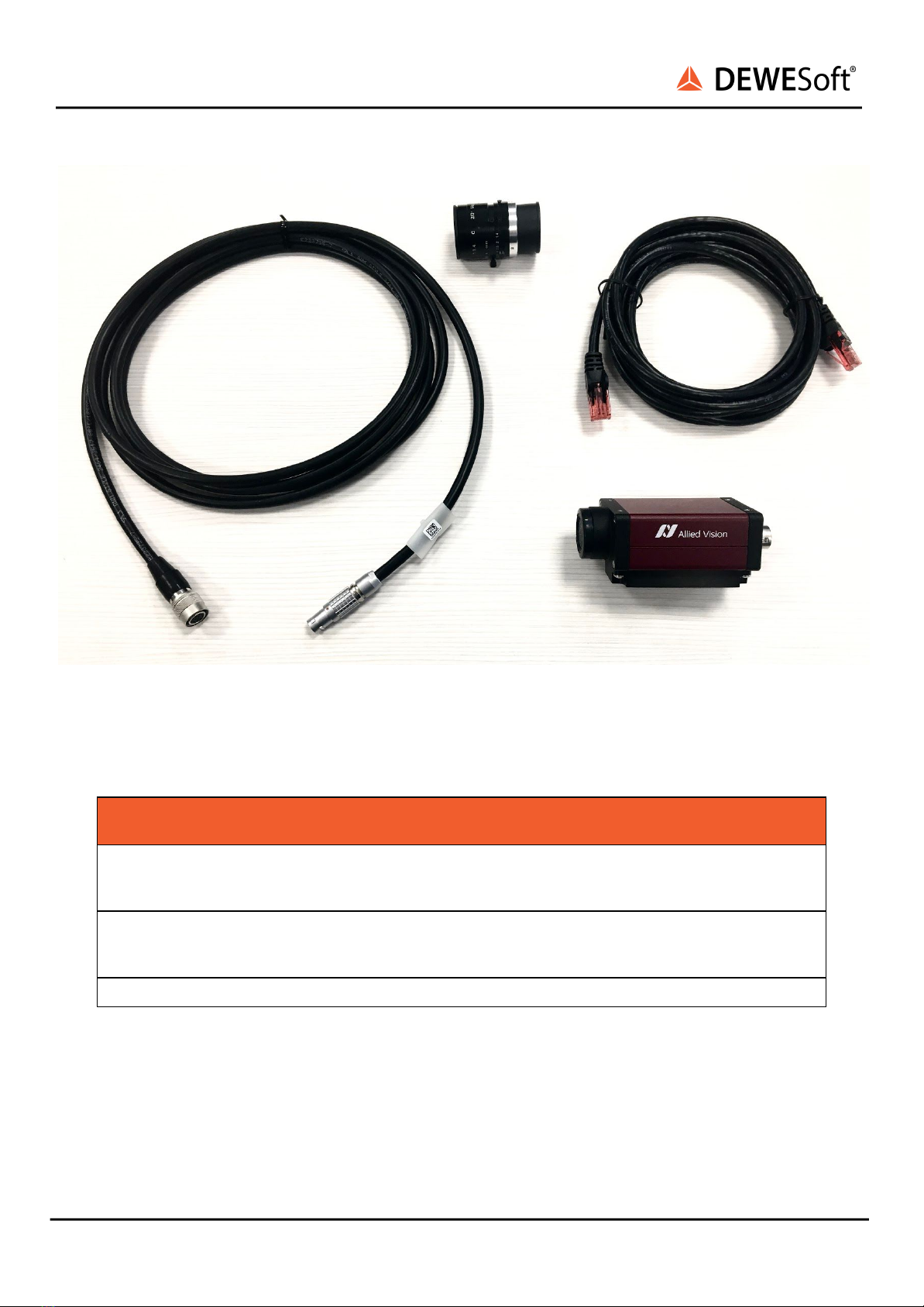
The DS-CAM-88c/DS-CAM-120c/DS-CAM-175c/DS-CAM-320c are a high-speed Gigabit-Ethernet cameras
with following key data:
●DS-CAM-88c: 88 fps @ VGA (640x480)
●DS-CAM-120c: 120 fps @ VGA (640x480)
●DS-CAM-175c: 178 fps @ VGA (640x480)
●DS-CAM-320c: 328 fps @ VGA (640x480)
●Color
●Auto-gain
●Auto-shutter (also fixed shutter possible)
●Auto-white balance
●Triggered and free-run mode
●Standard C-Mount
●Small compact form factor
●Low power consumption
●Ruggedized (high-shock and vibration resistant, aluminium housing)
●Real-time data streaming with full resolution
The camera supports the high-performance industrial standard “GigE Vision”. The standard introduced
in 2006 provides a framework for transmitting high-speed video and related control over Ethernet
networks.
The benefits are: high speed data transfer rates up to 1GBit/s (based on 1000Base-T) connectible to every
standard GigE Ethernet port and cable lengths up to 100m.
DewesoftX® uses OptoStream SDK for communication with cameras that support GigE Vision standard.
Important
For best performance we recommended using a SSD for storing data. A disk write rate of 100
MByte/s should be established, especially if using more than 1 camera.
3.1. System Requirements
●1 Gigabit-Ethernet port
●High-performance PC (Core i5 CPU or better recommended, 4 GB RAM and high performance
SSD storage disc)
●DewesoftX®
●The latest OptoStream SDK
●Dewesoft GigE driver (cdv)
DS-CAM-88c / DS-CAM-120c / DS-CAM-175c / DS-CAM-320c DS-V20-2 5/40

DS-CAM-88c / DS-CAM-120c / DS-CAM-175c / DS-CAM-320c
TECHNICAL REFERENCE MANUAL
4. Technical data
4.1. Specifications
DS-CAM-88
DS-CAM-120
DS-CAM-175
DS-CAM-320
Color option
Color
✓
✓
✓
✓
Monochrome
-
-
-
-
Optical specifications
Image sensor
Sony ICX414
Sony ICX618
Sony IMX273
Sony IMX287
Sensor type
CCD
CCD
CMOS
CMOS
Resolution
VGA 640x480
VGA 640x480
1456x1088
728x544
FPS
88 FPS @ 640x480
167 FPS @ 320x240
289 FPS @ 160x120
120 FPS @ 640x480
68 FPS @ 1456x1088
116 FPS @ 1280x720
145 FPS @ 800x600
178 FPS @ 640x480
266 FPS @ 728x544
328 FPS @ 640x480
Sensor size
1/2'' (12.7 mm
diagonal)
1/4'' (6.35 mm
diagonal)
1/2.9'' (6.3 mm
diagonal)
1/2.9'' (6.3 mm
diagonal)
Pixel size (in μm)
9.9 x 9.9
5.6 x 5.6
3.45 x 3.45
6.9 x 6.9
Dynamic range
35 dB auto-gain
function
32 dB auto-gain
function
71.6 dB auto-gain
function
74.4 dB auto-gain
function
Shutter
Full frame
Full frame
Electronic Global
Shutter
Electronic Global
Shutter
Shutter time
autoshutter
function
autoshutter
function
26 ns - 60 s
(autoshutter
function)
58 ns - 60 s
(autoshutter function)
Auto-white
balance
✓
✓
✓
✓
Mechanical specifications
Operating
temperature
+5... +45°C
+5... +45°C
+5... +45°C
+5... +45°C
Operating
humidity
25% - 80%
(non-condensing)
25% - 80%
(non-condensing)
20% - 80%
(non-condensing)
20% - 80%
(non-condensing)
Dimensions
44 (H) x 29 (W) x
86.4 (D) mm
1.73 (H) x 1.14 (W) x
3.40 (D) in
44 (H) x 29 (W) x
86.4 (D) mm
1.73 (H) x 1.14 (W) x
3.40 (D) in
44 (H) x 29 (W) x
86.4 (D) mm
1.73 (H) x 1.14 (W) x
3.40 (D) in
44 (H) x 29 (W) x 86.4
(D) mm
1.73 (H) x 1.14 (W) x
3.40 (D) in
Lens mount
C-mount
C-mount
C-mount
C-mount
DS-CAM-88c / DS-CAM-120c / DS-CAM-175c / DS-CAM-320c DS-V20-2 6/40

DS-CAM-88c / DS-CAM-120c / DS-CAM-175c / DS-CAM-320c
TECHNICAL REFERENCE MANUAL
Connectors
Screw mount GigE
RJ45
EIAJ (Hirose) 12 pin
Screw mount GigE
RJ45
EIAJ (Hirose) 12 pin
Screw mount GigE
RJ45,
Hirose
HR10-10R-12PA(73)
Screw mount GigE
RJ45,
Hirose
HR10-10R-12PA(73)
Conformity
CE
FCC
RoHS
GigE Vision
GenICam (PoE IEEE
802.3at)
CE
FCC
RoHS
GigE Vision
GenICam (PoE
IEEE 802.3at)
CE
FCC
RoHS
GigE Vision
GenICam (PoE IEEE
802.3at)
CE
FCC
RoHS
GigE Vision
GenICam (PoE IEEE
802.3at)
Power specifications
Supply voltage
+8 to +30 VDC
+8 to +30 VDC
+8 to +30 VDC
+8 to +30 VDC
Power-over-
Ethernet
option
option
option
option
Power
consumption
3.6 W
3.6 W
3.2 W
3.2 W
Illustration 1: Technical drawing with basic dimensions
DS-CAM-88c / DS-CAM-120c / DS-CAM-175c / DS-CAM-320c DS-V20-2 7/40

DS-CAM-88c / DS-CAM-120c / DS-CAM-175c / DS-CAM-320c
TECHNICAL REFERENCE MANUAL
Illustration 2: Technical drawing of aluminum adapter plate
DS-CAM-88c / DS-CAM-120c / DS-CAM-175c / DS-CAM-320c DS-V20-2 8/40

DS-CAM-88c / DS-CAM-120c / DS-CAM-175c / DS-CAM-320c
TECHNICAL REFERENCE MANUAL
Illustration 3: Aluminum adapter mounter on the camera.
4.2. Scope of supply
4.2.1. DS-CAM camera versions
Type
Usage
DS-CAM-88c
Color camera
DS-CAM-120c
Color camera
DS-CAM-175c
Color camera
DS-CAM-320c
Color camera
4.2.2. Accessories
Type
Usage
LENS-AZURE-1614mm
Azure 1614mm C-MOUNT lens
CABLE-UTP-CAT.6-3m
RJ45 CAT 6 cable for data
ALU_PLATE_ADAPTER
Aluminum plate adapter with 3x 1/4-20 UNC thread
CABLE-H12f-L1B7m-3m
Power and sync cable, 12-pin Hirose connector to 7-pin Lemo
connector. For CAM-BOX usage only.
CASE_XTRABAG-300
Carrying bag
DS-CAM-88c / DS-CAM-120c / DS-CAM-175c / DS-CAM-320c DS-V20-2 9/40

DS-CAM-88c / DS-CAM-120c / DS-CAM-175c / DS-CAM-320c
TECHNICAL REFERENCE MANUAL
Illustration 2: Scope of supply for DS-CAM
4.2.3. Optional
Type
Usage
H12f-L1B2m-L00B4m-3m
Power and sync cable, 12-pin Hirose connector splitted to
2-pin Lemo connector and 4-pin Lemo connector. For SIRIUS
usage.
H12f-L1B7m-L00B4m-3m
Power and sync cable, 12-pin Hirose connector splitted to
7-pin Lemo connector and 4-pin Lemo connector. For
DEWE-43 usage only (max 1 per unit).
DS-CAM-IP67
IP67 upgrade kit
DS-CAM-88c / DS-CAM-120c / DS-CAM-175c / DS-CAM-320c DS-V20-2 10/40

DS-CAM-88c / DS-CAM-120c / DS-CAM-175c / DS-CAM-320c
TECHNICAL REFERENCE MANUAL
Illustration 3: H12f-L1B2m-L00B4m-3m and H12f-L1B7m-L00B4m-3m are the equal except the pinout is different from one
another. Refer to the tables below
Illustration 16: Pinout of marked connector for
H12f-L1B2m-L00B4m-3m cable.
Pin
Name
Description
1
+12V
Power (+9...+36 V DC)
1
GND
Ground
DS-CAM-88c / DS-CAM-120c / DS-CAM-175c / DS-CAM-320c DS-V20-2 11/40

DS-CAM-88c / DS-CAM-120c / DS-CAM-175c / DS-CAM-320c
TECHNICAL REFERENCE MANUAL
Illustration 15: Pinout of marked connector for
H12f-L1B7m-L00B4m-3m
Pin
Name
Description
1
-
-
2
-
-
3
-
-
4
-
-
5
-
-
6
+12V
Power (+9...+36 V DC)
7
GND
Ground
4.3. Connections
On the rear side of the camera there are two connectors. The 12pin HIROSE connector (matching part:
Hirose HR10A10P-12S(73)) contains the power, trigger and other digital pins. Ethernet connector pinout
according to the standard.
Illustration 2: Connecting scheme
DS-CAM-88c / DS-CAM-120c / DS-CAM-175c / DS-CAM-320c DS-V20-2 12/40

DS-CAM-88c / DS-CAM-120c / DS-CAM-175c / DS-CAM-320c
TECHNICAL REFERENCE MANUAL
4.3.1. Power/Trigger connector pinout
Illustration 3: 12pin Hirose connector (matching part: Hirose HR10A-10P-12S(73)) on camera rear side
Pin
Signal
1
GND (for Power and RS232)
2
Power (+8...+30 V DC)
3
-
4
Camera In 1 (TRIGGER)
5
-
6
Camera Out 1 (open emiter, max. 20 mA)
7
Camera In GND
8
RxD (RS232)
9
TxD (RS232)
10
Camera Out Power (for digital outputs)
11
Camera In 2
12
Camera Out 2
DS-CAM-88c / DS-CAM-120c / DS-CAM-175c / DS-CAM-320c DS-V20-2 13/40

DS-CAM-88c / DS-CAM-120c / DS-CAM-175c / DS-CAM-320c
TECHNICAL REFERENCE MANUAL
4.3.2. SIRIUS® connection example
In this picture you see a typical SIRIUS measurement instrument, consisting of one SBOX unit
(integrated PC) on bottom and one SIRIUS slice on top (from rear side).
The camera is directly connected to the Gigabit-LAN port. The second cable to the camera contains the
power (from SBOX Power out) and the trigger, connected to the SYNC port of the SIRIUS slice. The
camera frames are now in perfect sync with the analog data acquired by DewesoftX®.
Hint
Even if the camera is connected, synching to other SIRIUS devices is still possible, because
there are different pins used on the SYNC port for triggering/synching.
Illustration 4: SIRIUS SBOX with 1 SIRIUS slice connected to the DS-CAM-120c (per cable H12f-L1B7m-L00B4m-3M)
DS-CAM-88c / DS-CAM-120c / DS-CAM-175c / DS-CAM-320c DS-V20-2 14/40

DS-CAM-88c / DS-CAM-120c / DS-CAM-175c / DS-CAM-320c
TECHNICAL REFERENCE MANUAL
4.2.4. Connecting multiple cameras
Illustration 7: CAM-BOX2
If you need to connect more than one camera, there is a special “CAM-BOX2” available, which consists of
●wide-range voltage input (9-36V)
●an industrial Gigabit-Ethernet-Switch (without Power-over-Ethernet! No supply for
DS-CAM-600!)
●Power and Sync distribution for up to 4 cameras.
●Small dimensions: 115 x 62 mm (front) and 135 mm deep
DS-CAM-88c / DS-CAM-120c / DS-CAM-175c / DS-CAM-320c DS-V20-2 15/40

DS-CAM-88c / DS-CAM-120c / DS-CAM-175c / DS-CAM-320c
TECHNICAL REFERENCE MANUAL
Camerabox connector
Illustration 8: CAM-BOX2 pinout
Mating cable connector: FGG.1B.307CLAD52
Pin
Pin assignment
1
-
2
-
3
-
4
CLK
5
-
6
+12V
7
GND
Power supply connector
Illustration 8: Power supply
Mating cable connector: FGGJ.1B.302CLLD42Z
Pin
Pin assignment
1
+9V...36V
2
GND
DS-CAM-88c / DS-CAM-120c / DS-CAM-175c / DS-CAM-320c DS-V20-2 16/40

DS-CAM-88c / DS-CAM-120c / DS-CAM-175c / DS-CAM-320c
TECHNICAL REFERENCE MANUAL
Sync connector
Illustration 8: Sync connector
Mating cable connector: FGG.00.304CLAD27Z
Pin
Pin assignment
1
-
2
-
3
CLK
4
GND
4.2.5. Connections Overview
Illustration 9: DS-CAM to SIRIUS connection example.
DS-CAM-88c / DS-CAM-120c / DS-CAM-175c / DS-CAM-320c DS-V20-2 17/40

DS-CAM-88c / DS-CAM-120c / DS-CAM-175c / DS-CAM-320c
TECHNICAL REFERENCE MANUAL
Illustration 10: DS-CAM to DEWE43 connection example.
Important
Maximum of one camera is permissible to connect due to power limitation of DEWE-43A.
Illustration 11: DS-CAM, CAM-BOX1 for power supply and synchronization. Expanding up to four cameras. Ethernet data cable is
wired directly to the network card of the PC.
Important
If you use more than one camera use an external power supply (PS-200-L2B3f)
for CAM-BOX1.
DS-CAM-88c / DS-CAM-120c / DS-CAM-175c / DS-CAM-320c DS-V20-2 18/40

DS-CAM-88c / DS-CAM-120c / DS-CAM-175c / DS-CAM-320c
TECHNICAL REFERENCE MANUAL
Illustration 12: 4x DS-CAM, CAM-BOX3 for power supply and synchronization.
Important
If you use more than one camera use an external power supply (PS-200-L2B3f)
for CAM-BOX2.
4.3. Benchmarks
The following tests were done with SIRIUS SBOX and 1 to 4 cameras connected to the CAM-BOX2. Setup:
●1 to 4 cameras connected over CAM-BOX2
●SBOX: 128GB SSD -> max 190 MByte/s write rate
●CPU: Intel Core i7 QM57; 2.0GHz; 4GB RAM
●camera(s) clocked by SIRIUS
●Dewesoft X1 SP7 b358 GigEVisionSDK Version 2.7.0.1
●GigE Camera driver v3.5 (Plugin)
●storing data to file, video buffer stable around 0..1%
●with checked "optimize for switched network"
Achieved framerates (fps)
1 camera
x res
y res
DS-CAM-88c
DS-CAM-120c
640
480
88
120
320
240
165
195
320
120
280
300
DS-CAM-88c / DS-CAM-120c / DS-CAM-175c / DS-CAM-320c DS-V20-2 19/40

DS-CAM-88c / DS-CAM-120c / DS-CAM-175c / DS-CAM-320c
TECHNICAL REFERENCE MANUAL
2 cameras
x res
y res
DS-CAM-88c
DS-CAM-120c
640
480
88
120
320
240
165
195
320
120
280
210
3 cameras
x res
y res
DS-CAM-88c
DS-CAM-120c
640
480
88
90
320
240
165
195
320
120
280
210
4 cameras
x res
y res
DS-CAM-88c
DS-CAM-120c
640
480
88
60
320
240
165
195
320
120
280
210
Hint
Results (FPS) should be considered only as approximate MAX values. Writing speed of the disk
may be a limiting factor (we used SSD!). We recommend to test cameras with your setup at
about 0.8*max_FPS and higher to find where corrupted image, frame lost or buffer overrun will
occur.
5. Installation
5.1. DewesoftX® full installer
For DewesoftX® all the drivers come with the full installer, if you select the option “GigE camera driver”
during installation. To check if the drivers are installed, go to Options → Installed extensions and see if the
checkbox “GigE” is visible. If not, execute the full installer again, choose the Modify option and enable
the checkbox of GigE camera.
DS-CAM-88c / DS-CAM-120c / DS-CAM-175c / DS-CAM-320c DS-V20-2 20/40
Other manuals for DS-CAM-88c
3
This manual suits for next models
3
Table of contents
Other DEWESOFT Camcorder manuals