Pag. 7
GB
•The professionally trained personnel who install the machine and connect the electricity,
will explain to the user how to operate the machine and which safety measures to use.
•The installer will provide practical demonstrations and leave written instructions which are provided with
the machine.
•This machine is only to be used for the purpose for which it was designed.
Any other use is considered improper and dangerous.
•The machine is not to be used by untrained personnel.
•Never use the machine if any of the protections (microswitches, panels or other) provided
by the manufacturer are missing.
•Do not use the machine to wash objects not compatible with those indicated by the
manufacturer.
•All repair work must be done by the manufacturer or an authorized service center using
original spare parts.
•Failure to observe this may affect the safety of the machine.
•The power supply should be turned off when the machine is not being used.
•Never put magnetic items close to the machine
•Never use the machine if not provided with the filters in the tank
3.2 SAFETY FEATURES
The board can recognize various breakdowns.
Faults are easily seen from the messages on the screen (5 and 6) and from any interruption of the
operations
WARNING! Turning the machine off and then on again resets the warning, which will appear again if
the problem has not been resolved.
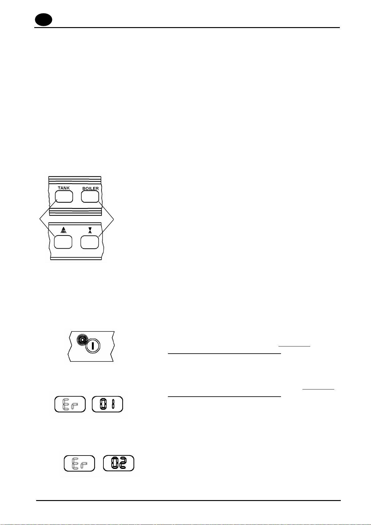
DISPLAYED MESSAGE ANOMALY FOUND:
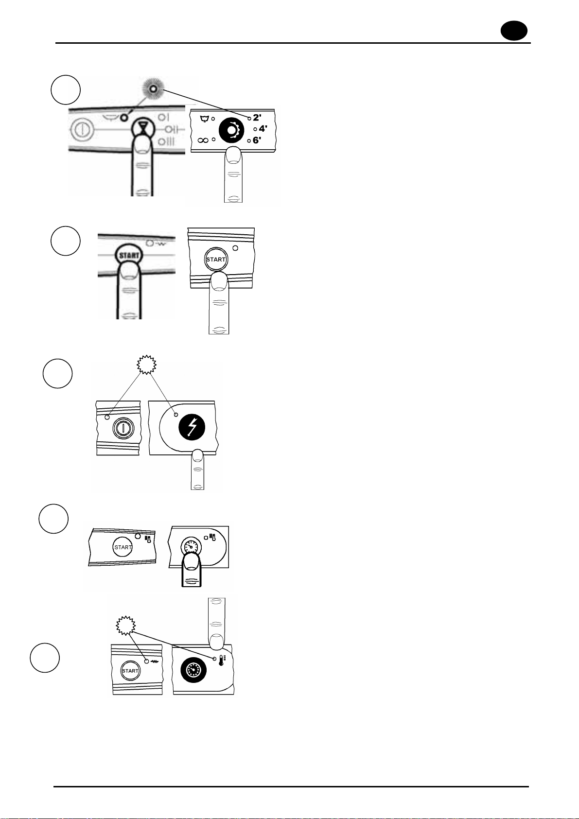
POWER LIGHT BLINKING (*): the inlet water control is not
activated. To reactivate the control, unplug the appliance and
then plug it back into the electric mains. If the signal
reappears, contact a qualified technician.
NO WATER AT INLET (*): no rinsing. Once the problem has
been solved, perform a complete washing cycle. If the signal
reappears, contact a qualified technician.
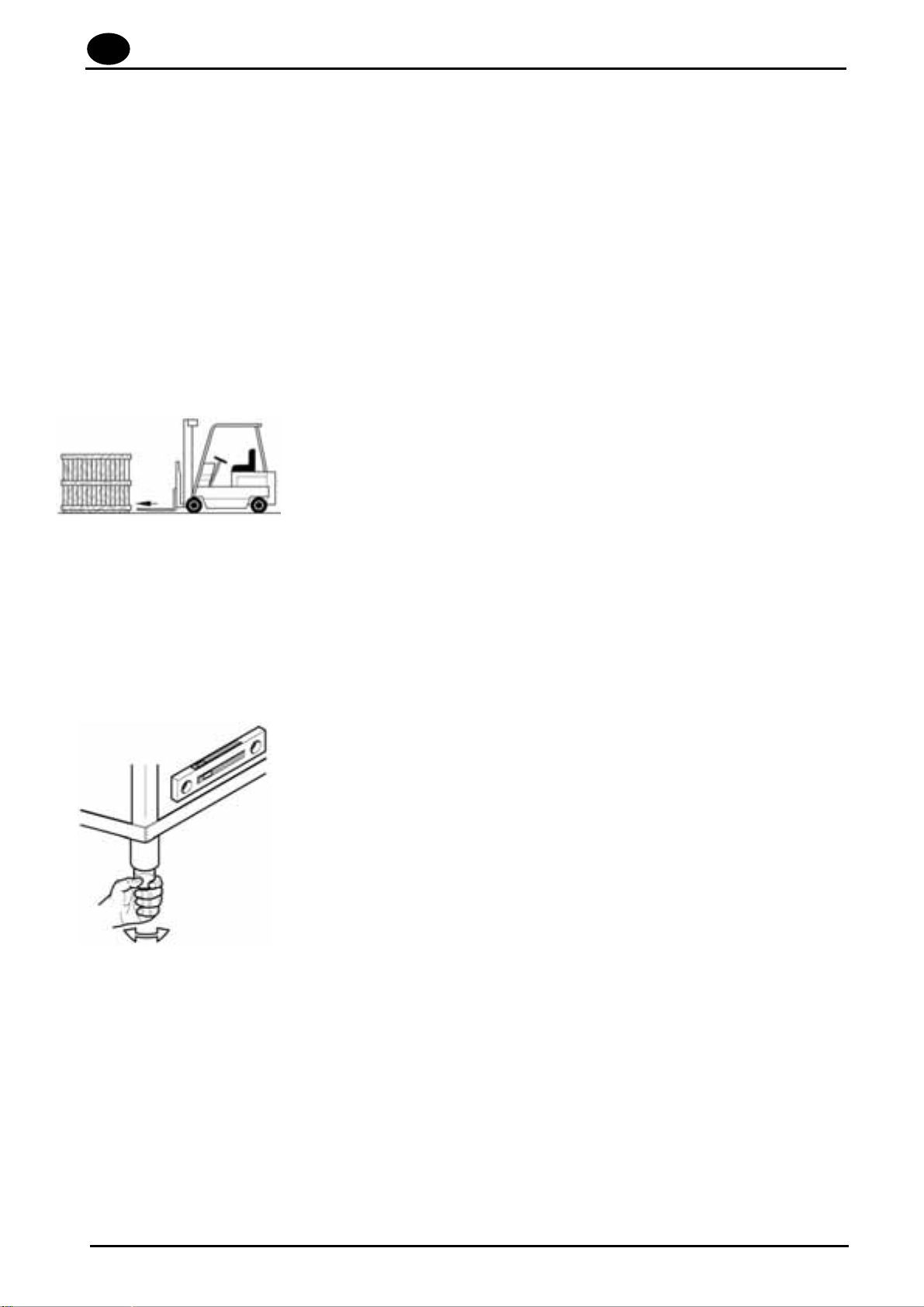
DRAINAGE TIME OUT:
•The tank was not drained completely. Check the overflow.
Try running a new drainage cycle.
•CRP – SP version,the tank was not drained correctly.
Check the draining line is unobstructed. If the error
message appears during the final self-cleaning cycle, try
running a new cycle.
Boiler (6)
Tank (5)
Boiler (6)
Tank (5)