DIEBOLD NIXDORF D1064 User manual

D1064
Customer Display
Operator Manual
01750364416 B
Customer/Partner Use
This document is property of Diebold Nixdorf and is intended for customer/partner use. A written
license agreement with Diebold Nixdorf is not required to use this material.

Copyright © Diebold Nixdorf. Copyright protection is claimed for each revision listed in the document his-
tory, as of the date indicated. All Rights Reserved.
This document contains proprietary information of Diebold Nixdorf, Incorporated or its subsidiaries (col-
lectively “Diebold Nixdorf“) and may include information that is protected by copyright, trademark and
patent laws in the US, Germany, and globally. All rights, including rights created by patent grants or reg-
istration of a utility model or design, are reserved.
No part of this document may be translated, reproduced, stored in a retrieval system, or transmit-
ted, in any form or by any means: electronic, mechanical, photocopying, recording, or otherwise,
without prior written permission from Diebold Nixdorf. Any violations of the foregoing may give
rise to a claim for damages.
If the document pages state the information is confidential (or words of similar import), then this
document is intended solely for the use of the employees or other personnel of Diebold Nixdorf
unless expressly authorized in writing by Diebold Nixdorf. Other uses of this information without
the express written consent of Diebold Nixdorf are prohibited.
This document should be treated as confidential material for security reasons. Any unauthorized
disclosure or use of confidential material may violate the U.S. Theft of Trade Secrets provisions
of Section 1832 of Title 18 of the United States Code as well as comparable laws in other jurisdic-
tions throughout the world, and may be punishable by fine and imprisonment.
This document and the information contained herein are provided AS IS AND WITHOUT WARRANTY.
In no event shall Diebold Nixdorf or its suppliers be liable for any special, indirect, or consequential dam-
ages of any nature resulting from the use of information in this manual. The information contained in this
document is subject to change without notice. When using the document for system implementation,
please call your authorized Diebold Nixdorf sales or service representative for any applicable changes.
Any trademarks, service marks, product names or company names not owned by Diebold Nixdorf, that
appear in this document are used for informational purposes only, and Diebold Nixdorf claims no rights
thereto, nor does such use indicate any affiliation with or any endorsement of Diebold Nixdorf or Diebold
Nixdorf products by the owners thereof.
Your use of this document and/or any of the information contained herein constitutes your agreement to
all of the terms stated on this page.
Copyright © 2022, Diebold Nixdorf
01750364416 B
ii

Table of Contents
1 Document History ...................................................................................................................... 1-1
2 About This Manual..................................................................................................................... 2-1
3 Introduction ................................................................................................................................ 3-1
3.1 Features at a glance ..........................................................................................................3-1
3.2 Care of D1064....................................................................................................................3-1
4 Manufacturer’s Declaration and Approval............................................................................... 4-1
5 Supplier’s Declaration of Conformity ...................................................................................... 5-1
6 Overview ..................................................................................................................................... 6-1
6.1 D1064 on a stand...............................................................................................................6-1
6.2 D1064 on a pole.................................................................................................................6-2
6.3 D1064 on a A-Series AIO or Display..................................................................................6-3
7 Initial Setup................................................................................................................................. 7-1
7.1 Unpacking and Checking the Delivery Unit........................................................................7-1
7.2 Mounting Options and Connection Cables.........................................................................7-1
7.3 Installing the D1064 Display...............................................................................................7-4
7.3.1 Installing System to the Stand ............................................................................ 7-4
7.3.2 Installing System to the Pole............................................................................... 7-8
7.3.3 Installing System to a A-Series AIO or Display................................................... 7-12
8 Display Characteristics ............................................................................................................. 8-1
8.1 Screen Coordinates ...........................................................................................................8-1
9 Display Commands.................................................................................................................... 9-1
9.1 Control Characters and ESC Sequences...........................................................................9-1
9.1.1 Backspace........................................................................................................... 9-2
9.1.2 Line Feed ............................................................................................................ 9-2
9.1.3 Carriage Return................................................................................................... 9-2
9.1.4 Delete to End of Line .......................................................................................... 9-2
9.1.5 Clear Screen ....................................................................................................... 9-3
9.1.6 Set Cursor Position ............................................................................................. 9-3
9.1.7 Set Country Code ............................................................................................... 9-4
9.1.8 Display Identification ........................................................................................... 9-5
9.1.9 Character Set Identification................................................................................. 9-6
9.1.10 Firmware Identification........................................................................................ 9-6
9.1.11 Set Compatibility Mode ....................................................................................... 9-7
9.1.12 Read Current Compatibility Mode....................................................................... 9-7
9.1.13 Set Baud Rate for Serial Port.............................................................................. 9-8
9.1.14 Set Serial Port..................................................................................................... 9-9
9.1.15 Set Character Encode/Decode Mode ................................................................. 9-9
9.1.16 Read Character Encode/Decode Mode .............................................................. 9-10
9.1.17 Start Self-Test ..................................................................................................... 9-10
9.1.18 Restore Configuration Data to Factory Default ................................................... 9-10
Copyright © 2022, Diebold Nixdorf
01750364416 B
iii

Table of Contents
9.2 ESC / POS Commands......................................................................................................9-11
9.2.1 Supported Commands ........................................................................................ 9-11
9.2.2 Unsupported Commands .................................................................................... 9-12
9.2.3 USB Commands ................................................................................................. 9-13
9.2.4 Status Bytes Definitions ...................................................................................... 9-18
9.2.5 Middleware.......................................................................................................... 9-19
10 Technical Data............................................................................................................................ 10-1
10.1 Dimensions (mm) ...............................................................................................................10-2
Copyright © 2022, Diebold Nixdorf
01750364416 B
iv

Table of Contents
Illustration directory
Figure 6-1 D1064 mounted on a Stand ...................................................................................6-1
Figure 6-2 D1064 mounted on a pole......................................................................................6-2
Figure 6-3 D1064 on a A-Series AIO or Display......................................................................6-3
Figure 7-1 Threading the cable through the stand ..................................................................7-5
Figure 7-2 Connect the RJ45 cable.........................................................................................7-5
Figure 7-3 Secure the RJ45 cable...........................................................................................7-6
Figure 7-4 Secure the Display to the stand .............................................................................7-6
Figure 7-5 Secure cable in the stand.......................................................................................7-7
Figure 7-6 Finished installation................................................................................................7-7
Figure 7-7 Mount adapter to pole ............................................................................................7-9
Figure 7-8 Connect the cable ..................................................................................................7-9
Figure 7-9 Attach cable to strain relief.....................................................................................7-10
Figure 7-10 Mount the Display to the adapter ...........................................................................7-10
Figure 7-11 Secure adapter on the pole....................................................................................7-11
Figure 7-12 Finished installation................................................................................................7-11
Figure 7-13 Remove the VESA cover........................................................................................7-13
Figure 7-14 Remove the breakaway..........................................................................................7-13
Figure 7-15 Removing the cable cover......................................................................................7-14
Figure 7-16 Loosen adapter screws ..........................................................................................7-14
Figure 7-17 Threading the RJ45 cable ......................................................................................7-15
Figure 7-18 Removing screws from the D1064 .........................................................................7-15
Figure 7-19 Connecting the RJ45 plug......................................................................................7-16
Figure 7-20 Mounting the adapter to D1064..............................................................................7-16
Figure 7-21 Removing top screws ............................................................................................7-17
Figure 7-22 Mounting the adapter to the stand .........................................................................7-17
Figure 7-23 Mount the Display to the adapter ...........................................................................7-18
Figure 7-24 Threading the USB cable .......................................................................................7-18
Figure 7-25 Connect the cable ..................................................................................................7-19
Figure 7-26 Mounting the cable cover .......................................................................................7-19
Figure 7-27 Cable routing overview...........................................................................................7-20
Figure 7-28 Mount the VESA cover...........................................................................................7-21
Figure 7-29 Finished installation................................................................................................7-21
Copyright © 2022, Diebold Nixdorf
01750364416 B
v

1
1 Document History
Part Number Date Remarks
01750364416 A 02/2022 Creation of the manual
01750364416 B 04/2022 Addition of part numbers and smaller improvements
Copyright © 2022, Diebold Nixdorf
01750364416 B
1-1
2
2 About This Manual
This documentation is intended to help you to work with the customer display and to serve as a refer-
ence work. The detailed table of contents helps you find the desired information quickly and easily.
NOTE
Note
This is how notes are displayed in this manual.
WARNING
Warning
This is how warnings are displayed in this manual.
Copyright © 2022, Diebold Nixdorf
01750364416 B
2-1

3
3 Introduction
The D1064 is a rejuvenate successor of the BA64-2 Customer Display for the A-Series Family of POS
system. The radiant and high contrast nature of the VFD technology makes it an excellent choice for a
customer display. The D1064 operates in either USB or RS232 mode depending on the cable option you
select. There are three mounting options to choose from, for mounting on the back of the A-Series POS
terminal, pole-mount or standalone on the counter top.
3.1
3.1 Features at a glance
• VFD version allow for worldwide application
• Backward compatible to BA63/BA64
• Epson ESC POS command set support
• Loadable character sets
• Unicode support
• JavaPOS 1.13 support
• Flexible mounting options
3.2
3.2 Care of D1064
Clean your customer display regularly with an appropriate surface cleaning product.
Make sure that the device is switched off and that no moisture is allowed to get into the inside of the de-
vice.
Copyright © 2022, Diebold Nixdorf
01750364416 B
3-1

4
4 Manufacturer’s Declaration and Approval
General authorization
This device complies with the requirements of the directive 2014/30/EC
with regard to “Electromagnetic Compatibility” and 2014/35/EC "Low Volt-
age Directive" and RoHS directive 2011/65/EU.
Therefore, you will find the CE mark on the device or packaging.
FCC-Class A Declaration
This equipment has been tested and found to comply with the limits for a Class A digital device, pursuant
to part 15 of the FCC Rules. These limits are designed to provide reasonable protection against harmful
interference when the equipment is operated in a commercial environment. This equipment generates,
uses, and can radiate radio frequency energy and, if not installed and used in accordance with the in-
struction manual, may cause harmful interference to radio communications.
Operation of this equipment in a residential area is likely to cause harmful interference in which case the
user will be required to correct the interference at his expense.
Modifications not authorized by the manufacturer may void users’ authority to operate this device.
This device complies with part 15 of the FCC Rules. Operation is subject to the following two conditions:
(1) This device may not cause harmful interference, and (2) this device must accept any interference, in-
cluding interference that may cause undesired operation.
CAN ICES-3 (A)/NMB-3 (A)
Copyright © 2022, Diebold Nixdorf
01750364416 B
4-1

Manufacturer’s Declaration and Approval
Safety information
This device conforms to the corresponding safety regulations for information technology devices, includ-
ing electronic office machines for use in the office environment.
• If the device is moved from a cold environment to a warmer room where it is to be operated, conden-
sation could occur. The device must be completely dry before being put into operation. Therefore an
acclimatization time of at least two hours should be accounted for.
• Lay all cables and supply lines so that nobody can tread on them or trip over them.
• Data cables should neither be connected nor removed during electrical storms.
• This equipment is not suitable for use in locations where children are likely to be present.
• Protect the device from vibrations, dust, moisture and heat, and only transport the device in its origi-
nal packaging (to protect it against
impact and blows).
• Take care to ensure that no foreign objects (e.g. paper clips) or liquids can get into the inside of the
device, as this could cause electrical shocks or short circuits.
• In case of emergencies (e.g. damaged housing, liquid or foreign objects getting into the device), the
device should be switched off immediately, the mains plug of the BEETLE or PC should be removed,
and the Diebold Nixdorf customer service should be contacted.
Generally you should connect IT-devices only to power supply systems with separately guided protective
earth conductor (PE), known as TN-S networks. Do not use PEN conductors! Please also observe the
recommendations of the norm DIN VDE 0100, part 540, Appendix C2, as well as EN50174-2, §5.4.3.
Warranty
Diebold Nixdorf guarantees generally a warranty engagement for 12 months beginning with the date of
delivery. This warranty engagement covers all those damages which occur despite a normal use of the
product.
Damages because of
• improper or insufficient maintenance,
• improper use of the product or unauthorized modifications of the product,
• inadequate location or surroundings
will not be covered by the warranty.
For further information of the stipulation, look at your contract.
All parts of the product which are subject to wear and tear are not included in the warranty engagement.
Please order spare parts at the Diebold Nixdorf customer service.
Copyright © 2022, Diebold Nixdorf
01750364416 B
4-2

Manufacturer’s Declaration and Approval
Instructions for maintenance
Clean your display regularly with an appropriate surface cleaning product. Make sure that the device is
switched off, connector cables are unplugged and that no moisture is allowed to get into the inside of the
device.
Please observe the maintenance and cleaning instructions for each of the components. These instruc-
tions can be found in their respective chapters.
Recycling
Environmental protection does not begin when time comes to dispose of the display; it begins with the
manufacturer. The compact display is manufactured without the use of CFCs and CCHS and is pro-
duced mainly from reusable components and materials.
The processed plastics can, for the most part, be recycled. Even the precious metals can be recovered,
thus saving energy and costly raw materials. Please do not stick labels onto plastic case parts. This
would help us to re-use components and material.
You can protect our environment by switching on your display only when it is actually needed. If possi-
ble, even avoid the stand-by-mode as this wastes energy, too. Also switch your display off when you
take a longer break or finish your work.
There are still some parts that are not reusable. Diebold Nixdorf guarantees the environmentally safe
disposal of these parts in a Recycling Center, which is certified pursuant to ISO 9001 and ISO 14001.
So don’t simply throw your device on the scrap heap when it has served its time, but take advantage of
the environmentally smart, up-to-date recycling methods.
Please contact your competent branch or the Recycling Center Paderborn (for European countries) for
information on how to return and re-use devices and disposable materials under the following mail ad-
dress:
Email: [email protected]
We look forward to your mail.
Copyright © 2022, Diebold Nixdorf
01750364416 B
4-3

5
5 Supplier’s Declaration of Conformity
Product Description: Customer Display
Model: D1064
Party issuing Supplier’s Declaration of Conformity
Diebold Nixdorf Singapore PTE. LTD.
30A Kallang Place, #04-01
Singapore 339213
Phone: +65 6747 3828
Responsible Party – U.S. Contact Information
Diebold Nixdorf
50 Executive Pkwy
PO Box 2520
Hudson, OH 44236 / USA
Phone: +1 330 490 5049
FCC Compliance Statement (for products subject to Part 15)
This device complies with Part 15 of the FCC Rules. Operation is subject to the following two conditions:
(1) This device may not cause harmful interference, and (2) this device must accept any interference re-
ceived, including interference that may cause undesired operation.
Copyright © 2022, Diebold Nixdorf
01750364416 B
5-1

6
6 Overview
Below you will find reference pictures showing the D1064 in various installation situations. The installa-
tion components, such as the pole itself, are not part of the scope of delivery of the D1064.
NOTE
The pictures may differ in detail from the product you received.
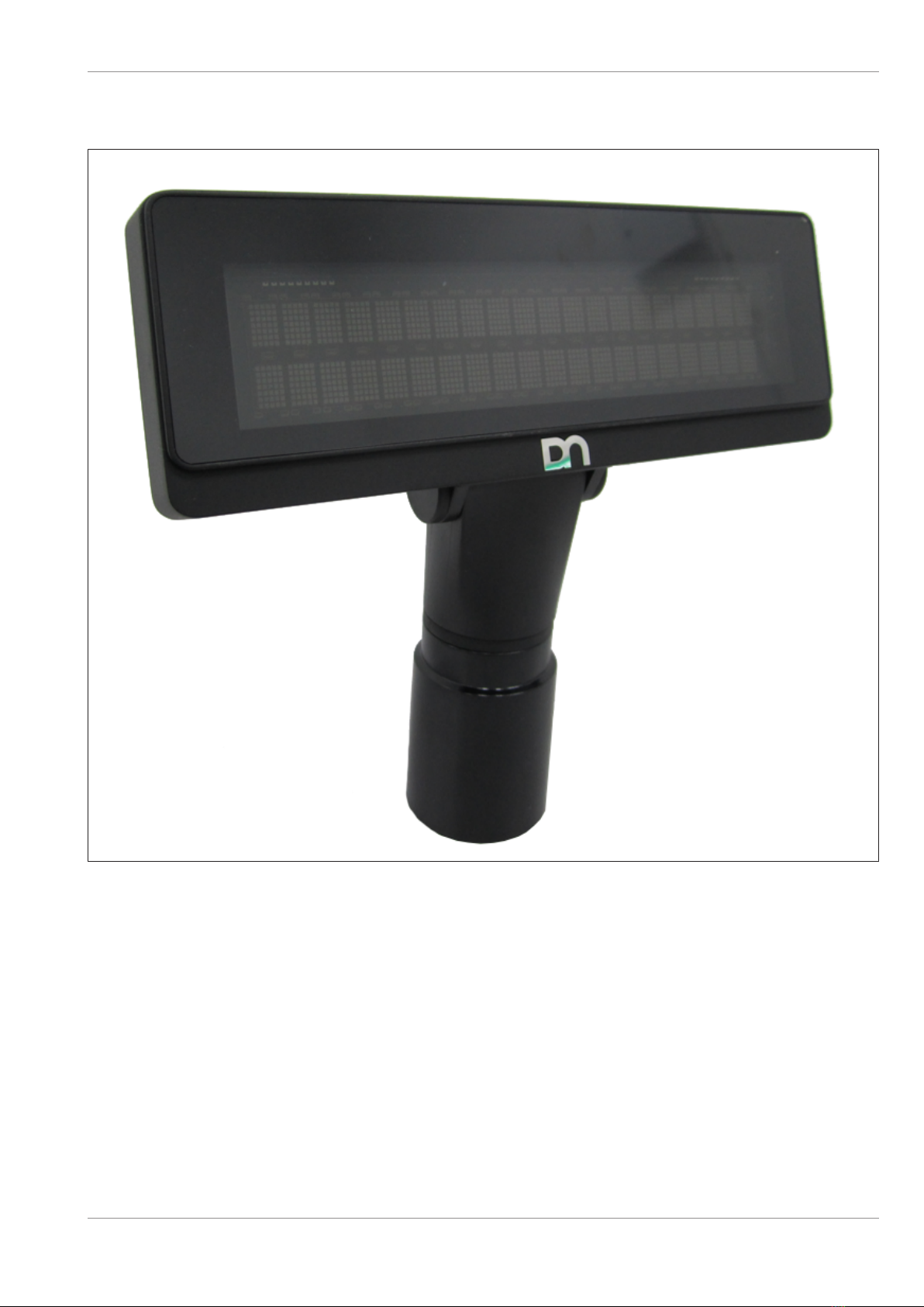
6.1
6.1 D1064 on a stand
TD-01596-01
Figure6-1: D1064 mounted on a Stand
Copyright © 2022, Diebold Nixdorf
01750364416 B
6-1
Overview
6.2
6.2 D1064 on a pole
TD-01596-02
Figure6-2: D1064 mounted on a pole
Copyright © 2022, Diebold Nixdorf
01750364416 B
6-2
Overview
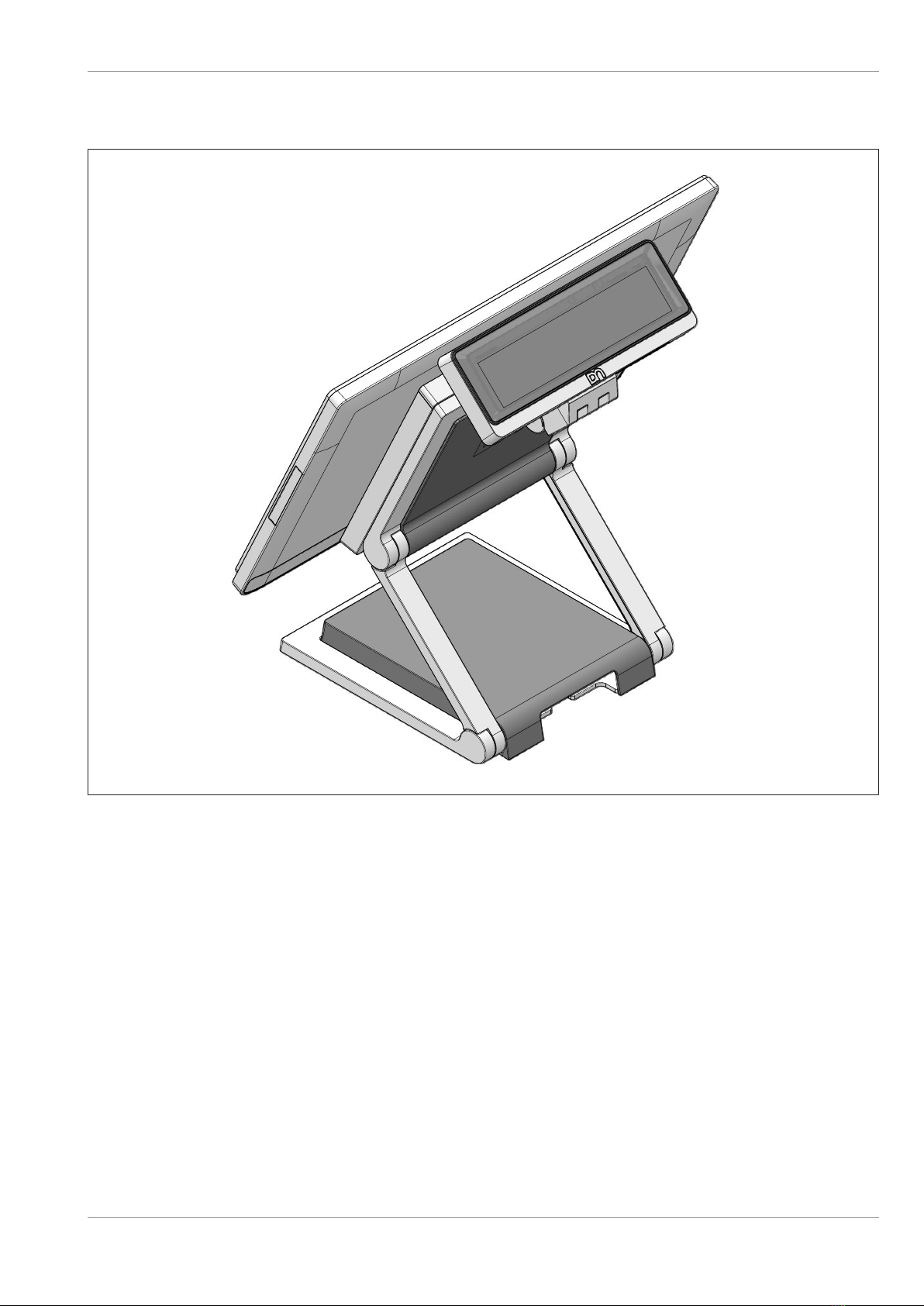
6.3
6.3 D1064 on a A-Series AIO or Display
TD-01596-03
Figure6-3: D1064 on a A-Series AIO or Display
Copyright © 2022, Diebold Nixdorf
01750364416 B
6-3
7
7 Initial Setup
In this chapter you will find the information you need to prepare for the installation of the system.
7.1
7.1 Unpacking and Checking the Delivery Unit
Unpack the parts and check whether the delivery corresponds to the information on the delivery note.
The delivery includes the respective screen module.
Mounting adapters can be ordered separately depending on the intended installation situation. Data ca-
bles required for operation can be ordered separately. If damage has occurred during transport or the
contents of the package do not match the delivery note, inform your Diebold Nixdorf sales office immedi-
ately.
Only transport the unit in its original packaging.
7.2
7.2 Mounting Options and Connection Cables
Various mounting options and connection cables are available for installing the BA64 in the different in-
stallation scenarios.
The mounting options and cables must be purchased separately from the main unit.
The following list shows an overview of the D1064 configuration components and their detailed contents.
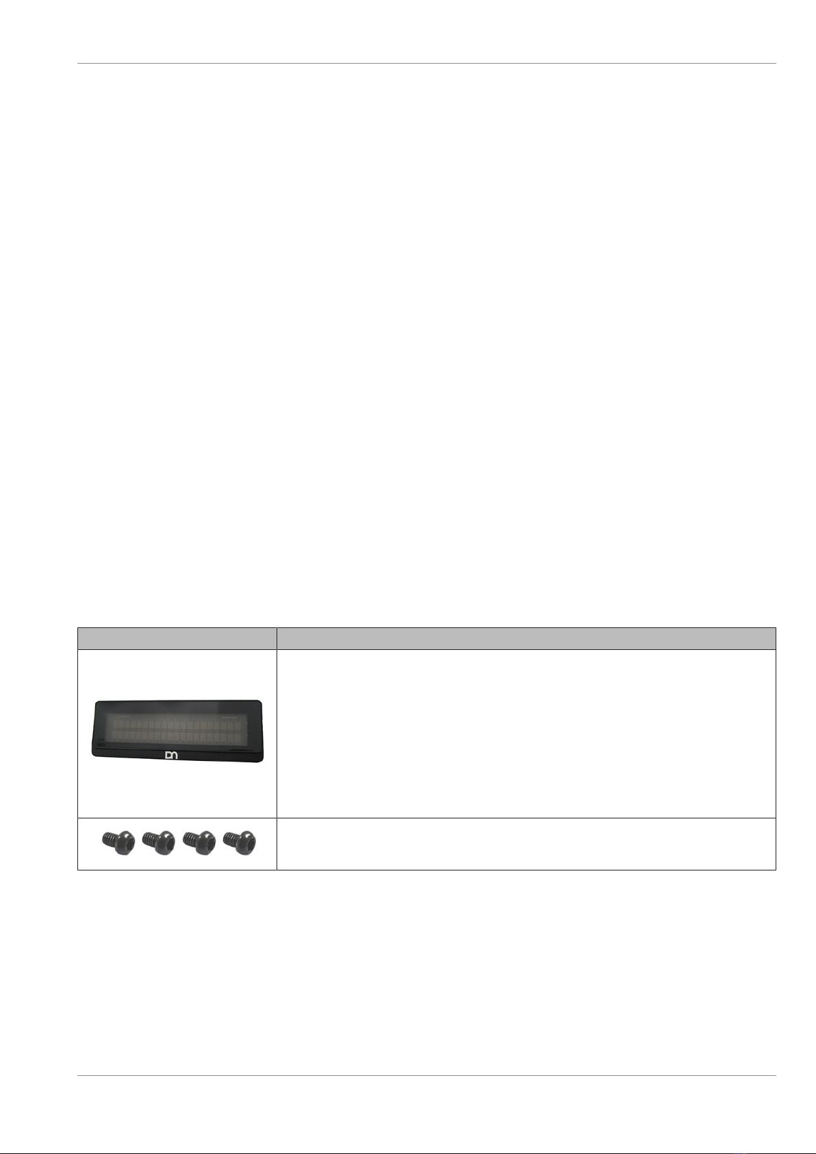
D1064 consists of:
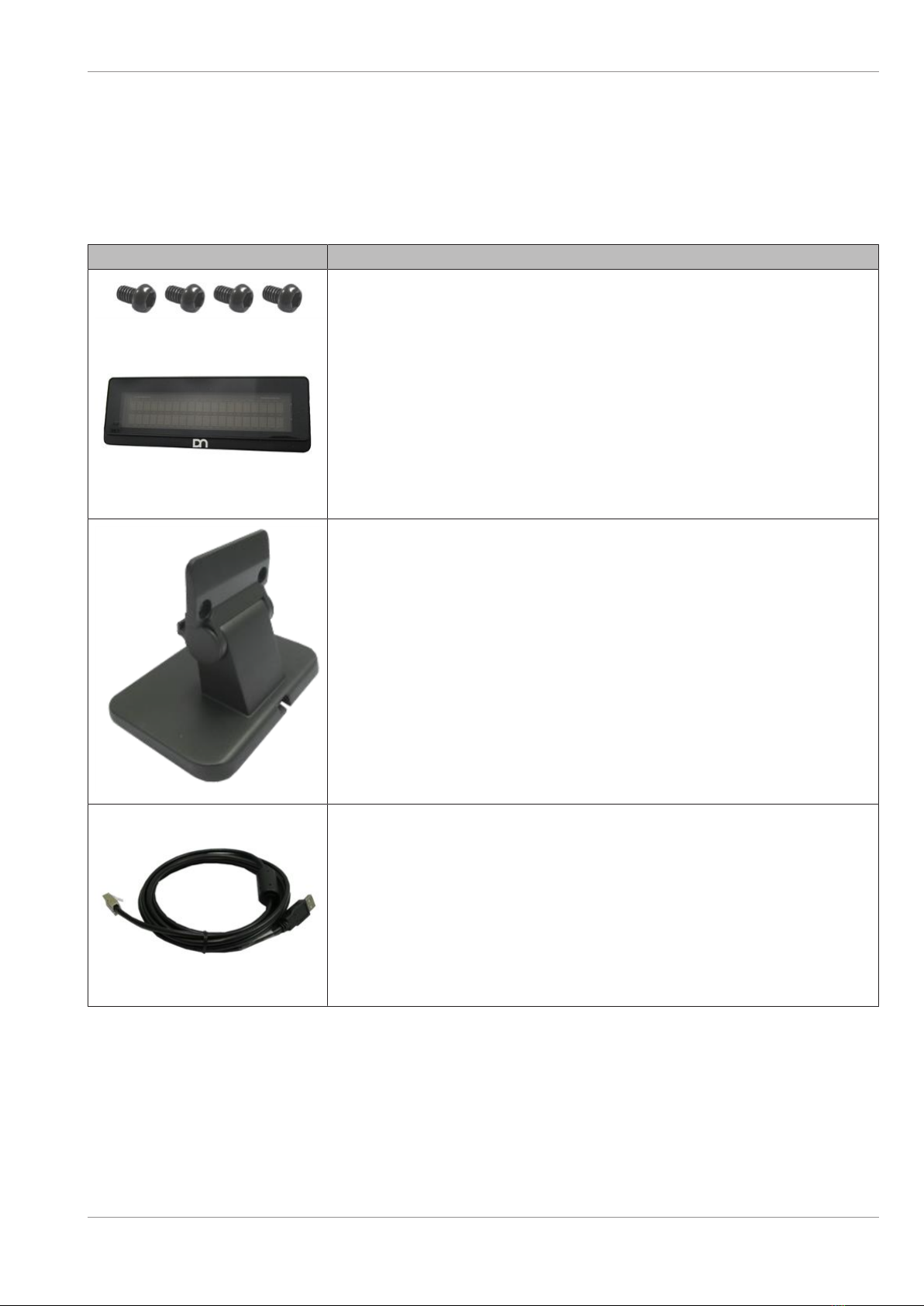
Illustration Item
1x D1064 Display
4x Torx screw M4x6 with black zinc
Copyright © 2022, Diebold Nixdorf
01750364416 B
7-1
Initial Setup
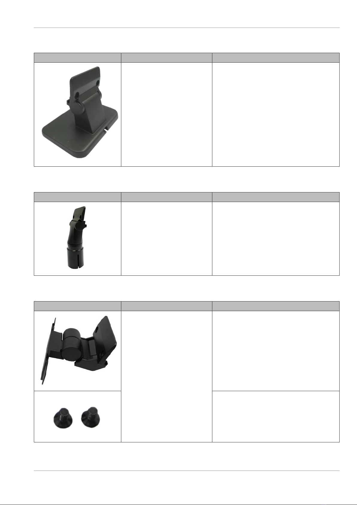
Stand consist of:
Illustration Part Number Item
01750279877 1x Stand Assembly
Pole Adapter consists of:
Illustration Part Number Item
01750279878 1x Pole mount assembly
A-Series dual display adapter consists of:
Illustration Part Number Item
01750342563 1x Display adapter
2x Torx countersunk screws M4x8
(Part number: 01750335349)
Copyright © 2022, Diebold Nixdorf
01750364416 B
7-2

Initial Setup
Connection cables:
Illustration Part Number Item
01750243981
01750243983
01750243985
USB to RJ45 cable, 1.5m, black
USB to RJ45 cable, 3.0m, black
USB to RJ45 cable, 5.0m, black
01750349276 RJ45 to USB cable (0,42.)
01750243975
01750243977
01750243979
RS232 to RJ45 cable, 1.5m, black
RS232 to RJ45 cable, 3.0m, black
RS232 to RJ45 cable, 5.0m, black
Copyright © 2022, Diebold Nixdorf
01750364416 B
7-3
Initial Setup
7.3
7.3 Installing the D1064 Display
7.3.1
7.3.1 Installing System to the Stand
To install the D1064 Display to a pole you will need the following parts:
Illustration Item
1x Unit of D1064 Display
1x Unit of Stand
1x Unit of connection cable
Copyright © 2022, Diebold Nixdorf
01750364416 B
7-4
Initial Setup
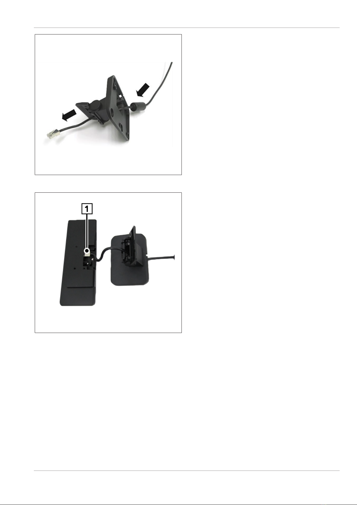
TD-01596-04
Figure7-1: Threading the cable through the stand
1. Thread the RJ45-end of the connection cable
through the stand.
TD-01596-05
Figure7-2: Connect the RJ45 cable
2. Connect the RJ45 connector (1) to the D1064
Copyright © 2022, Diebold Nixdorf
01750364416 B
7-5
Table of contents
Other DIEBOLD NIXDORF Monitor manuals

DIEBOLD NIXDORF
DIEBOLD NIXDORF NextGen AIO D2080 User manual

DIEBOLD NIXDORF
DIEBOLD NIXDORF D1156 User manual

DIEBOLD NIXDORF
DIEBOLD NIXDORF D2156 User manual

DIEBOLD NIXDORF
DIEBOLD NIXDORF BA82 User manual

DIEBOLD NIXDORF
DIEBOLD NIXDORF D1104 User manual

DIEBOLD NIXDORF
DIEBOLD NIXDORF D2150 User manual

DIEBOLD NIXDORF
DIEBOLD NIXDORF NextGen AIO D1150 User manual

DIEBOLD NIXDORF
DIEBOLD NIXDORF NextGen AIO D1101 User manual

DIEBOLD NIXDORF
DIEBOLD NIXDORF K-two User manual

DIEBOLD NIXDORF
DIEBOLD NIXDORF BA90 User manual


