Digihertz Audio DAE428 User manual

DIGITAL LOUDSPEAKER MANAGEMENT
MUTEMUTE MUTE/CHANNEL MENU (PRESS&HOLD 3S)
IN- A IN -B I N- C IN- D OU T1 O UT2 OUT 3 OU T4 OUT 5 OU T6 OUT 7 OU T8
PK
+12
+6
0
-6
-12
-24
PK
+12
+6
0
-6
-12
-24
PK
+12
+6
0
-6
-12
-24
PK
+12
+6
0
-6
-12
-24
PK
+12
+6
0
-6
-12
-24
PK
+12
+6
0
-6
-12
-24
PK
+12
+6
0
-6
-12
-24
PK
+12
+6
0
-6
-12
-24
PK
+12
+6
0
-6
-12
-24
PK
+12
+6
0
-6
-12
-24
PK
+12
+6
0
-6
-12
-24
DIGIT AL CROSSO VER PARAMETER
RECALL
SAVE/ENTER
MAIN MENU
CURSOR
For more product information, please refer to the CD with the device
USER MANUAL
DAE428
DAE428
DAE226
DAE224

product; or
c) The product has been exposed to rain; or
d) The product does not appear to operate normally or exhibits a
marked change in performance; or
e) The product has been dropped or the enclosure damaged.
14. Do not attempt to service the product beyond that described in the
user-maintenance instructions. All other servicing should be
referred to qualified service personnel.
15. WARNING - Do not place objects on the product's power
cord or place it in a position where anyone could trip over, walk
on or roll anything over it. Do not allow the product to rest on or
to be installed over power cords of any type.
Improper installations of this type create the possibility of fire
hazard and/or personal injury.
16. The power-supply cord should be unplugged from the outlet when
the products is completely power off from the electric power
sources and electric networks .
Only use it below the attitude of 2000ms for safety
application.
Only use it in nontropical climate condition for safety
application.
The lightning flash with arrowhead symbol within an
equilateral triangle is intended to alert the user to the
presence of uninsulated dangerous voltage within the
product's enclosure, that may be of sufficient magnitude to
constitute a risk of electric shock to persons.
The exclamation point within an equilateral triangle is
intended to alert the user to the presence of important
operation and maintenance (servicing) instruction in the
literature accompanying the appliance.
RISK OF ELECTRIC SHOCK
DO NOT OPEN
CAUTION: TO REDUCE THE RISK OF ELECTRIC
SHOCK DO NOT REMOVE COVER ( OR BACK)
NO USER-SERVICEABLE PARTS INSIDE
REFER SERVICING TO QUALIFIED PERSONNEL
CAUTION
1
2
1
8
5
467
9 10
MUTEMUTE MUTE/CHANNEL MEN U (P RE SS &H OL D 3S )
IN- A IN -B I N-C I N- D OU T1 OU T2 OUT3 O UT 4 OU T5 OUT6 O UT 7 OU T8
PK
+12
+6
0
-6
-12
-24
PK
+12
+6
0
-6
-12
-24
PK
+12
+6
0
-6
-12
-24
PK
+12
+6
0
-6
-12
-24
PK
+12
+6
0
-6
-12
-24
PK
+12
+6
0
-6
-12
-24
PK
+12
+6
0
-6
-12
-24
PK
+12
+6
0
-6
-12
-24
PK
+12
+6
0
-6
-12
-24
PK
+12
+6
0
-6
-12
-24
PK
+12
+6
0
-6
-12
-24
DIGIT AL CROSSOVER PARAMETER
RECALL
SAVE/ENTER
MAIN MENU
CURSOR
11 12
Front Panel
WIFI Adapter Interface
7-Segments LED Input Level Indicator
7-Segments LED Output Level Indicator
132×32 Dot-Matrix LCD
MAIN MENU Navigation Buttons
RECALL Button
1
2
3
4
5
6
PARAMETER Adjustment Rotary Encoder
USB Interface
Input MENU / MUTE Buttons and the Related LEDs
Output MENU / MUTE Buttons and the Related LEDs
CURSOR Navigation Buttons
SAVE / ENTER Buttons
7
8
9
10
11
12
There are three models in the series ( 4 in 8 out, 2 in 6 out, 2 in 4 out).
Please choose the suited model for your application.
Version:V1.0
IMPORTANT SAFETY INSTRUCTION
Please read the basic protective measure as below before using.
1. Please read all the safety instruction before using the product.
2. This product must be earthed. If it should be malfunction or break
down, grounding provides a path of least resistance for electric
current to reduce risk of electric shock.
3. This product is equipped with a cord having an equipment-
grounding conductor and a grounding plug. The plug must be
plugged into an appropriate outlet that is properly installed and
earthed in accordance with all local codes and ordinance.
4. DANGER - Improper connection of the equipment-grounding
conductor can result in a risk of electric shock. Check with a
qualified electrician or serviceman if you are in doubt as to
whether the product is properly grounded. Do not modify the
plug provided with the product - if it will not fit the outlet, have
a proper outlet installed by a qualified electrician.
5. To reduce the risk of injury, close supervision is necessary when the
product is used near children.
6. Do not use this product near water-for example, near a bathtub,
washbowl, kitchen sink, in wet basement or near a swimming pool
or the lake.
8. This product should be located so that its location or position does
not interfere with its proper ventilation.
9. This product should be located away from heat sources such as
radiators, heat registers or other products that produce heat.
10. The product should be connected to a power supply only of the type
described on the operation instructions or as marked on the product.
11. The power-supply cord of the product should be unplugged from the
outlet when left unused for a long period of time. When unplugging
the power-supply cord, do not pull on the cord, but grasp it by the
plug.
12. Care should be taken so that object do not fall and liquid are not
spilled into the enclosure through opening.
13. The product should be serviced by qualified service personnel
when:
a) The power-supply cord or the plug has been damaged; or
b) Objects have been fallen, or liquid has been spilled into the
7. Whether used this product alone or connected to the power
amplifier, speaker or headset, excessive volume may cause
permanent hearing loss. Don't use for a long time in large or any
volume may cause discomfort. If you feel any hearing loss or
tinnitus, Please seek medical advice.
DAE428
3
≤2000m

2
MA INS I N~
90 V-2 50V AC /5 0-6 0Hz
RS23 2
1
用户程式 菜单
1 2
反馈抑 制 话筒激励 效果模式 超低音模式
34存储
话筒模式
音乐模式
音乐激励 音乐音 量/编辑(按下) 效果音量
话筒音 量
话筒
2 3
6
5
3
4
OUTPUT5
Rear Panel
1
Mains Input & Fuse Box
RS232 PC Control Interface
RS485 Input
1
2
3
2
System Connection Diagram
PC
4
5
6
8 / 6 / 4 Channel Output Sockets
4 / 2 Channel Input Sockets
RS485 Output
MA INS I N~
90 V-2 50V AC /5 0-6 0Hz
RS23 2
RS485 to USB
Adapter
RS485
INPUT
RS485
OUTPUT
Terminal Resistor
OUTPUT6
OUTPUT7
OUTPUT8
OUTPUT4
OUTPUT3
OUTPUT2
OUTPUT1
INPUT A
INPUT B
INPUT C
INPUT D
Power Amplifier
Loudspeaker
Power Amplifier Power Amplifier Power Amplifier
Loudspeaker Loudspeaker Loudspeaker Loudspeaker Loudspeaker Loudspeaker Loudspeaker
RS232
RS485
INPUT
RS485 OUTPUT
RS485 INPUT
RS485 OUTPUT
DIGITAL LOUDSPEAKER
MANAGEMENT
DIGITAL LOUDSPEAKER
MANAGEMENT
DSP Karaoke Processor
Mixing Console
MAIN S IN~
90V- 250VA C /50-6 0Hz
RS23 2
MAIN S IN~
90V- 250VA C /50-6 0Hz
RS23 2
There are three models in the series ( 4 in 8 out, 2 in 6 out, 2 in 4 out).
Please choose the suited model for your application.
There are three models in the series
( 4 in 8 out, 2 in 6 out, 2 in 4 out).
Please choose the suited model
for your application.
MA DE I N CH IN A
MA DE I N CH IN A
MADE IN C HINA
MADE IN C HINA

***.***
***
2 Front Panel Buttons and the Function
2.1 MUTE
2.1.1 Press the MUTE
Function: Switch between the state of mut e or not for each
channel.
Operation: Press MUTE within 2 second and then release it. The
states of mute or not is switchable for each channel.
2.1.2 Press and Hold the MUTE
Function: Enter in the parameter setting menu of some channel.
Operation: Press and hold the MUTE (about 3 seconds) of some
channel till the settings page displayed on LCD. Then
release it. The settings menu of this channel has been
entered.
2.2 PARAMETER Encoder
2.2.1 Rotate the Encoder
Function: Change the value or options of parameters. Rotate
clockwise to increase the value. Rotate anticlockwise to
decrease the value.
Operation: Rotate the encoder clockwise or anticlockwise.
2.2.2 Push the Encoder
Function: Lock and unlock. Push it for lock all buttons and
encoder, push again to unlock.
Operation: Push the encoder and release it.
2.3 MAIN MENU and
Function: A) Switch to different settings page of the same channel
at the channel parameter set menu.
B) Switch to different menus at program management and
configuration setting.
Operation: Press it and then release it.
2.4 CURSOR and
Function: Move the cursor position to change the parameter at the
cursor.
Operation: Press the button and then release.
2.5 RECALL
Function: A) Enter into user program menu.
B) Return to the root menu.
Operation: Press the button and then release.
2.6 SAVE / ENTER
Function: A) Enter in the menu of saving user program.
B) Enter in the next submenu or confirm the function.
Operation: Press the button and then release.
3 Front Panel Menu Operation
3.1 Common Operation for Channel Parameter Set
®Press and hold the MUTE (about 3 seconds)of some channel
and enter into the parameter settings menu of this channel.
®Press button MAIN MENU or to switch between different
pages in this channel.
®Press CURSOR or to move cursor position, and then
rotate the Rotary Encoder to adjust the value.
3.2 Various Operations for Channel Parameter Set
3.2.1 Input / Output Mute Set
®Press MUTE button of some channel within 2 seconds and
release it. Mute status will be reversed when press the button
each time.
®The LED in the MUTE button will bright red when the channel
is mute, vice versa.
®
®
®
◀ ▶
◀ ▶
◀ ▶
◀ ▶
3.2.2 Input / Output Gain Set
Press MAIN MENU ◀ or ▶ to switch to GAIN settings page.
Rotate the Rotary Encoder to change the value.
Can also press CURSOR ◀ or ▶ to change the cursor's
position below the value, in order to switch to other step, such
as 0.1dB or 1dB.
3
1 IN-A GAIN: -10.3dB
MEMORY
1 USER PROGRAM:1
Features
®24-bit DSP technology, high performance AKM AD/DA,
simple operation and excellent performance.
®4 in 8 out (2 in 6 out, 2 in 4 out) multi-kinds of crossover mode
for flexible configuration.
®Input /output volume control with the range -40dB to +12dB
and the minimum step 0.1dB .
®9 bands PEQ for each input / output, each band PEQ has
Parametric, L-Shelf 6dB , L-Shelf 12dB , High-Shelf 6dB,
High-Shelf 12dB. Each PEQ has Phase shifter setting with the
range 0°to 178°.
®PEQ frequency range: 19.7Hz to 21.9Hz, Gain range: -30dB to
+15dB , bandwidth: 0.017 to 4.750 Octave.
®31 bands GEQ for each input / output,
Gain range: -30dB to +15dB.
®Output high-pass and low-pass filter, each filter has multi-
kinds of slopes and types. Filter slope: 12dB/Oct 24dB/Oct
36dB/Oct 48dB/Oct. Filter type: Butterworth, Bessel,
Linkwitz-Riley.
®The maximum 2000.02ms delay for each input/output channel
with delay bypass switch.
The compressor in each input / output can be adjusted the
Threshold, Ratio, Attack-time, Release-time and knees.
Phase invert function is set in each input / output channel.
Channel setting copy function makes the adjusting much
easier.
Multi channel parameters can be set simultaneously via Multi-
channel linking function .
Friendly and intuitive online interface. USB, RS232, RS485 or
WIFI can be connected with PC.
Multi processor networking function. One computer can be
connected to 3 kinds of processors ( 4 in 8 out, 2 in 6 out, 2 in 4
out) with the maximum 32 pcs for each model.
132*32 Dot-matrix LCD, 7 segments input/output level
indicator LED.
Mute LED indicator , button LED indicator.
Wide voltage design: From 90V to 250Vac, 50/60Hz.
Operation
1 Power on
1.1 Plug in the power cable, turn on the power switch on the panel,
then the LCD shows the brand, model and the version.
1.2 When the loading is completed, the LCD shows the current
program number, name and the processor ID.
1/3-Octave ISO Spacing
From 19.7 Hz to 21.9 kHz.
®
®
®
®
®
®
®
®
®

4
3.2.3 Input / Output Delay Set
®Press MAIN MENU or to switch to DELAY settings page.
®Rotate the Rotary Encoder to change the parameters with the
step of 0.021ms.
◀ ▶
®
3.2.4 Input / Output PEQ Set
®Press MAIN MENU ◀ or ▶ to switch to PEQ settings page.
®Press CURSOR ◀ or ▶ to move the cursor position.
®Rotate the Rotary Encoder to adjust the parameters at the
cursor position.
®The frequency, gain of PEQ can be adjusted coarse or fine at the
cursor position.
3.2.5 Input / Output GEQ Set
®Press MAIN MENU ◀ or ▶ to switch to GEQ settings page.
®Press CURSOR ◀ or ▶ to move the cursor position.
®Rotate the Rotary Encoder to adjust the parameters at the
cursor position.
®Gain of GEQ can be adjusted coarse or fine at the cursor
position.
3.2.6 Input / Output EQ Bypass Set
®Press MAIN MENU ◀ or ▶ to switch to ALL BYPASS
settings page.
®Press CURSOR ◀ or ▶ to move the cursor position.
®Switch between PEQ ALL-BYPASS and GEQ BYPASS.
®Rotate the Rotary Encoder to adjust the parameters at the cursor
position.
3.2.7 Input / Output Compressor Set
®Press MAIN MENU ◀ or ▶ to switch to COMPRESS settings
page.
®Press CURSOR ◀ or ▶ to move the cursor position.
®Rotate the Rotary Encoder to adjust the parameters at the cursor
position.
3.2.8 Input / Output LINK set
®Press MAIN MENU ◀ or ▶ to switch to LINK settings page.
®Press CURSOR ◀ or ▶ to move the cursor position.
®Rotate the Rotary Encoder to adjust the parameters at the cursor
position.
®Press SAVE/ENTER into the link confirmation dialogs.
Can also press CURSOR ◀ or ▶ to change the cursor's
position below the value, in order to switch to other step, such
as 105ms, 10.5ms, 1.05ms, 0.105ms, 0.021ms, or adjust the
delay switch.
933.35mS
321.47m
2241.21ft
2 IN-A DELAY:
ON
3 IN-A PEQ 1 ON PEQ
31.3Hz +0.0dB 0.500
5 IN-A GEQ 19 OFF
1280 Hz +6.5dB
4 IN-A ALL-BYPASS
PEQ:OFF GEQ:OFF
6 IN-A COMPRESS OFF
+3.5dBu 4:1 AT: 25mS
RT: 200mS
®
◀ or ▶
◀ or ▶
◀ or ▶
◀ or ▶
◀ or ▶
®Rotary
Default is NO, no link setting. Switch between YES and NO
with the Rotary Encoder.
®Press SAVE/ENTER again to confirm the link setting.
Note: Yes is chosen as link set, the source channel parameters will
be copied to the target channel.
3.2.9 Data COPY of Input / Output Channel
®Press MAIN MENU to switch to COPY settings page.
®Rotate the Rotary Encoder to change the target channel.
®Press SAVE / ENTER into COPY confirmation dialogs.
®Default is NO, no copy operation. Switch between YES and NO
with the Rotary Encoder.
®Press SAVE / ENTER again to confirm the copy operation.
Note: At the copy set, the source channel parameters will be
copied to the target channel.
3.2.10 Output HIGH/LOW PASS FILTER Set
®Press MAIN MENU to switch to high/low-pass filter
settings page.
®Press CURSOR to move the cursor.
®Rotate the Rotary Encoder to adjust the parameters at the cursor
position.
®The frequency of high/low pass filter can be adjusted coarse or
fine at the cursor position.
3.2.11 Output PHASE Set
®Press MAIN MENU to switch to PHASE settings page.
®Rotate the Rotary Encoder to change PHASE parameter.
3.2.12 SOURCE Set
®Press MAIN MENU to switch to SOURCE settings
page.
Rotate the Encoder to change SOURCE parameter.
7 IN-A CHANNEL LINK
Link to IN-D: OFF
7 IN-A CHANNEL LINK
Are you sure ? NO
4 OUT1 HIGH_PASS_FILTER
1620Hz 12 dB Linkriley
2 OUT1 SET PHASE
Phase: 180°
9 OUT1 SET SOURCE
Source: IN-A+IN-B
8 IN-A CHANNEL COPY
COPY TO: IN-B
8 IN-A Copy data to IN-B
Are you sure ? NO

PROGRAM) as the follow picture displays.
®Rotate the Rotary Encoder to change the preset program
number.
®Press SAVE / ENTER to finish the operation of erasing user
program.
3.3.5 Device Address Setting
®Press RECALL to return to the root menu if entered channel
menu, or skip this step.
® Then press MAIN MENU ◀ or ▶ till the menu(SET DEVICE
ADDRESS) as the below picture displays.
®Rotate the Rotary Encoder to change the device address.
®Press SAVE / ENTER to finish the operation of device address
setting.
3.3.6
Press RECALL to return to the root menu if entered channel
menu, or skip this step.
◀ or ▶
◀ or ▶
Rotary E
Lock / Unlock the Device
®
®Then press MAIN MENU till the menu (LOCK
DEVICE) as the below picture displays.
®Press CURSOR to move cursor.
®Rotate the ncoder to change the lock type and
password.
®Press SAVE/ENTER to finish the lock operation.
5
3.3
3.3.1 Recall an User Program
Continuously press RECALL till the menu (LOAD USER
PROGRAM) as the below picture .
Rotate the Encoder to change the program number.
®Press SAVE/ENTER to finish the recall operation.
Program Management and Configuration Setting
®
displays
®Rotary
3.3.2 Store an User Program
®Press RECALL to return to the root menu if entered channel
menu, or skip this step.
®Then press SAVE / ENTER till the menu (STORE USER
PROGRAM) as the below picture displays.
®Press CURSOR ◀ or ▶ to move the cursor.
®Rotate the Rotary Encoder to change program number and
program name.
®Press SAVE/ENTER to finish the storing operation.
3.3.3 Recall a Preset Program
®Press RECALL to return to the root menu if entered channel
menu, or skip this step.
®Then press MAIN MENU ◀ or ▶ till the menu (LOAD
PRESET PROGRAM) as the below picture displays.
®Rotate the Rotary Encoder to change the preset program
number.
®Press SAVE / ENTER to finish the operation of recall preset.
3.3.4 Erase an User Program
®Press RECALL to return to the root menu if entered channel
menu, or skip this step.
®Then press MAIN MENU ◀ or ▶ till the menu(ERASE USER
3 LOAD USER PROGRAM:1
MEMORY
Loading User Program
Please Wait.... ..
4 STORE USER PROGRAM:1
MEMORY
Storing User P r o g r a m
Please Wait.... ..
2 LOAD PRESET PROGRAM:1
4x2Way Crossover
Loading Preset
Please Wait. . . . . .
5 ERASE USER PROGRAM:1
MEMORY
5 ERASE USER PROGRAM:1
Are you sure ? NO
Era s ing Use r P r ogra m
Please Wait. . . . . .
6 SET DEVICE ADDRESS
DEVICE ID: 1
Setting Device address
Please Wait.... ..
4 STORE USER PROGRAM:1
Are you sure ? NO
7 LOCK DEVICE
TYPE: Change & View
Password: 12345678
3.5 Parameter Range of Program Management and
Configuration Setting
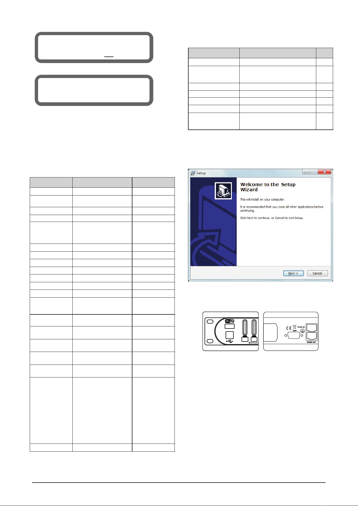
4 Software Installation
Puts the CD of accessories to the CD-ROM of computer, open the
file SETUP.EXE in the CD to launch the software. When loading
menu is showed, click the NEXT step by step till the installation is
completed.
5 PC Online Operation
5.1 One Processor Communication Link with PC:
Multi-types as USB, RS232, RS485 etc.
Note: The ID of User Interface should be set to the same with
the processor in order to the succeed online.
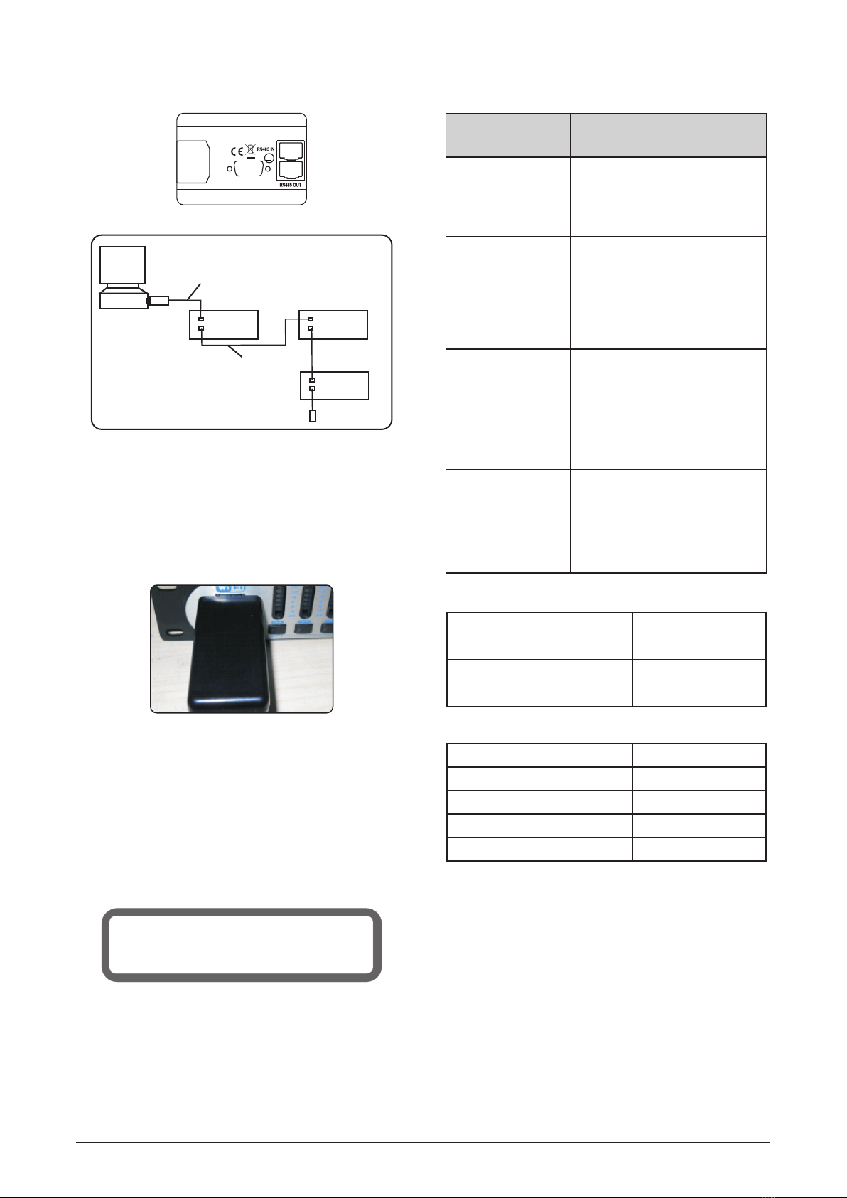
5.2 Multi Processors Communication Link with PC: RS485
®
®
®
®
®
Note: 1 For the same model processor, each device ID should be
set differently.
2 USB-RS485 convertor and the terminal resistor are the
optional accessories.
Use USB-RS485 convertor and Cat 5e cable to connect PC with
RS485-IN interface of the first device.
Use Cat 5e cable to connect RS485-OUT interface of the first
device with RS485-IN interface of the second device.
Use Cat 5e cable to connect RS485-OUT interface of the
second device with RS485-IN interface of the third device.
As step 3, use Cat 5e cable to connect multi devices. One PC
can be connected with three models of device ( 4 in 8 out, 2 in 6
out, 2 in 4 out) . The maximum number of connections are 32
processors.
Finally, RS485-OUT of the last device is connected with the
terminal resistor via Cat 5e cable.
3.3.8
®Rotary E
®Rotary E
Lock / Unlock the Buttons & Encoder
Push the ncoder to lock all Buttons and Rotary
Encoder.
Push ncoder again to unlock.
3.4 Channel’s Parameter Range
6
Lock succeed
MUTE
IN- A IN -B
PK
+12
+6
0
-6
-12
-24
PK
+12
+6
0
-6
-12
-24
MA INS I N~
90 V-2 50V AC /5 0-6 0Hz
MA DE I N CH IN A
RS23 2
Items
Range
Steps
Gain
-40dB ~ +12dB
1dB/0.1dB
Delay
ON/OFF, 0ms~2000.02ms
105/10.5/1.05/
0.105/0.021(ms)
PEQ Bands
1 ~ 9
-
PEQ Bypass
ON/OFF
-
PEQ Type
PEQ, Low-Shelf 6dB,
Low-Shelf 12dB, High-
Shelf 6dB, High-Shelf
12dB, Phase-Shifter
-
PEQ Frequency
19.7Hz ~ 21.9kHz
Coarse/Fine
PEQ Gain
-30dB ~ +15dB
1dB/0.1dB
PEQ Bandwidth
0.017 ~ 4.750 Oct
-
Phase-Shifter
0°~178°
1°
GEQ Bands
1 ~ 31
-
GEQ Bypass
ON/OFF
-
GEQ Gain
-30dB ~ +15dB
1dB/0.1dB
Compressor’s
Knee
Off/Hard knee/Soft knee
1/Soft knee 2/Soft knee
3/Soft knee 4/Soft knee 5
-
Compressor’s
Threshold
-20dB ~ +20dB
0.5dB
Compressor’s
Ratio
1.2, 1.5, 2, 3, 4, 6, 10, 20,
40, 128
-
Compressor’s
Attack-Time
0 ms ~100ms
1ms
Compressor’s
Release-Time
50 ms ~1000ms
50ms
High/Low-Pass
Filter Frequency
19.7Hz~21.9kHz
Coarse/Fine
High/Low-Pass
Filter Solpe
Flat, 12dB Bessel,
12dB Butterworth,
12dB Linkwitz-Riley,
24dB Bessel,
24dB Butterworth,
24dB Linkwitz-Riley,
36dB Bessel,
36dB Butterworth,
36dB Linkwitz-Riley,
48dB Bessel,
48dB Butterworth,
48dB Linkwitz-Riley
-
Phase Inverter
0°/180°
-
Items
Range
Steps
Load User Program
1 ~ 30
1
Store User Program
Program Number: 1 ~ 30
Program Name: ASCII Charater
1
Load Preset Program
1 ~ 10
1
Erase User Program
1 ~ 30
1
Set Language
Chinese / English
-
Set Device Address
1 ~ 32
1
Lock / Unlock Device
Type: Change, Change&View,
Change & Mute, Everything
Password: ASCII Charater
-
7 LOCK DEVICE
TYPE: Change & View
Are you sure ? NO
7
1
1
1
1
1
1
About the UI UI software manual.
5.3
5.4 WIFI Online Operation
Puts WIFI adapter into WIFI slot on the front panel, power on the
device, then use iPAD (or other devices) and the relative
software to do the wireless operation.
Note: WIFI adaptor is an optional part, not a standard
accessories.
Function: This operation will reset the device to factory default
settings, can also repair the issue caused by improper
operation.
WARNING - Any user program, device address and
lock setting that your have created will be lost.
Operation: Press and hold the button SAVE / ENTER, then turn on
the power switch in the rear panel till LCD displays the
following.
Operation, please refer to
6 Reset the Device
Resetting User Program
Please Wait...
7 Troubleshooting
Issues
No display on LCD
screen
1 Check if the power cable is plugged in.
2 Check if the fuse is burned.
3 Make sure that the power switch is ON.
Single processor can
not be connected with
PC for Online control.
1 Check if the communication cable is
correctly connected.
2 Close the software and connect the
communication cable again, then
open the software.
1 Check if the communication cable is
correctly connected.
2 Check if the ID addresses of the same
model
processors are set differently.
3 Close the software and reconnect PC
with the
first processor RS485 IN.
Open the software again.
No signal output at the
output channel
1 Check if the communication cable is
correctly
connected.
2 Check if MUTE LED is on. Disable
and LCD lights.
Accessories
Name
Software CD
USB Online Cable
User Manual
Options
Name
WIFI Adapter
USB-RS485 Converter
Terminal Resistor
Cat 5e Twisted-pair Cable
MA INS I N~
90 V-2 50V AC /5 0-6 0Hz
MA DE I N CH IN A
RS23 2
RS485 OUT
RS485 IN
RS485 OUT
RS485 IN
RS485 OUT
RS485 IN
USB-RS485
convertor Cat 5e cable
Ethernet cable
terminal resistor
max 32 pcs
PC
Quantity
Several
Quantity
Troubleshooting Methods
Multi
not be connected with
PC for Online control.
processors can
the mute function.

MATRIX
IN A
IN B
IN C
IN D
OUT1
OUT2
OUT3
OUT4
OUT5
OUT6
OUT7
OUT8
Gain
Gain
Gain
Gain
Gain
Gain
Gain
Gain
Mute
Mute
Mute
Mute
Mute
Mute
Mute
Mute
9PEQ
9PEQ
9PEQ
9PEQ
9PEQ
9PEQ
9PEQ
9PEQ
Phase
Phase
Phase
Phase
Phase
Phase
Phase
Phase
31GEQ
31GEQ
31GEQ
31GEQ
31GEQ
31GEQ
31GEQ
31GEQ
Compressor
Compressor
Compressor
Compressor
Compressor
Compressor
Compressor
Compressor
Delay
Delay
Delay
Delay
Delay
Delay
Delay
Delay
X-over
X-over
X-over
X-over
X-over
X-over
X-over
X-over
0°
0°
0°
0°
0°
0°
0°
0°
~180°
~180°
~180°
~180°
~180°
~180°
~180°
~180°
Signal Processing Flow Diagram
Specifications
8
The above design and specifications are subject to change without prior notice for product improvement.
4 / 2
8 / 6 / 4
8 kΩ
20 dBu+
> 55 dB
XLR-3Pin Female Connector
48 kHz
150 Ω
+20 dBu
XLR-3Pin Male Connector
-40dB ~ +12dB
0ms ~ 2000.02 ms
9
PEQ, 6dB / 12 dB Low-Shelf, 6dB / 12 dB High-Shelf, Phase Shifter
19.7 Hz ~ 21.9 kHz
-30 dB ~ +15 dB
0.017 ~ 4.750 Oct
31
1/3-Octave ISO Spacing From 19.7 Hz to 21.9 kHz
-30 dB ~ +15 dB
-20 dB ~ +20 dB
1.2, 1.5, 2, 3, 4, 6,
10, 20, 40, 128
0 ms ~100ms
50 ms ~1000 ms
19.7 Hz ~ 21.9 kHz
Bessel, Butterworth,
Linkwitz-Riley
12dB/Oct, 24dB , 36dB , 48dB/Oct/Oct /Oct
20 Hz ~ 20 kHz ±0.1dB
> 112 dB (A-Weighting)
< 95 dB
< 0.004% (1kHz, 1Vrms)
90 V-250 Vac, 50/60 Hz
T1AL , AC250 V
30 W
482×218×45 (mm)
3.6 kg
Number of Input Channel .........................................................................................................................................................
Number of Output Channel ...................................................................................................................................................
Input Impedance .....................................................................................................................................................................
Maximum Input Level .......................................................................................................................................................
Input CMRR .....................................................................................................................................................................
Input Sockets ......................................................................................................................................
Sampling Frequency ............................................................................................................................................................
Output Impedance .................................................................................................................................................................
Maximum Output Level .....................................................................................................................................................
Output Sockets .......................................................................................................................................
Input / Output Gain .................................................................................................................................................
Input / Output Delay ............................................................................................................................................
Input / Output PEQ Bands ............................................................................................................................................................
Input / Output PEQ Type .............................................................
Input / Output PEQ Frequency ............................................................................................................................
Input / Output PEQ Gain .......................................................................................................................................
Input / Output GEQ Bands ..........................................................................................................................................................
Input / Output PEQ Bandwidth ............................................................................................................................
Input / Output GEQ Gain .......................................................................................................................................
Input / Output Compressor Attack-Time ......................................................................................................................
Input / Output Compressor Release-Time ................................................................................................................
Input / Output GEQ Frequency .............................................................................
Input / Output Compressor Threshold .....................................................................................................................
Input / Output Compressor Ratio ....................................................................................................
Output High / Low-Pass Filter Frequency ...........................................................................................................
Output High / Low-Pass Filter Type ..........................................................................................
Output High / Low-Pass Filter Slope ................................................................................
Frequency Response ...................................................................................................................................
Dynamic Range ..........................................................................................................................................
Crosstalk ...........................................................................................................................................................................
THD+N .....................................................................................................................................................
Mains Input Voltage & Frequency ...............................................................................................................
Fuse Size ..............................................................................................................................................................
Power Rating .........................................................................................................................................................................
Dimensions .......................................................................................................................................................
Net Weight .. ........................... ..............................................................................................................................................
Gain
Gain
Gain
Gain
Mute
Mute
Mute
Mute
9PEQ
9PEQ
9PEQ
9PEQ
31GEQ
31GEQ
31GEQ
31GEQ
Compressor
Compressor
Compressor
Compressor
Delay
Delay
Delay
Delay
This manual suits for next models
2
Table of contents


