Digitrax SoundFX SDH166D User manual

© 2013 Digitrax, Inc. www.digitrax.com— 1 —
Features:
▪Digitrax SoundFX®Sound System
Your locomotives will sound in scale like the real thing with SoundFX
Customizable 8 Bit Sound
Works with SoundFX 8 Bit sound les
3 Simultaneous Voices
Downloadable Sound with Digitrax PR3 and SoundLoader 2.0 software
4 Megabit Onboard Sound Memory
1 Watt Sound Output
Cam input-synchronized Steam-chuff option for Steam locos
Scaleable Speed Stabilization(BEMF) optimized for sound operation
▪SoundFX does not require an external rate sensor to vary workload.
▪Factory 8 Ohm 16 x 26 x 9 mm box speaker on 10 Pin Plug design makes
installation quick and easy.
▪Smart Power Management-no more booster or programmer shutdowns!
▪Program CVs using any Digitrax Compatible Control system without having
to buy any extra equipment.
▪Digitrax Easy Connect 9 Pin Plug for Track, Motor and Function Control.
▪Series 6 Decoder Features.
▪Works with PX112-10 Power Extender.
▪Digitrax FX3Functions-Control lights and functions for prototypical lighting
effects and on/off control.
▪Congurable FX3Pulse Function available on all function outputs.
▪Digitrax LocoMotion®System – Lets your trains run like the real thing!
▪2 Digit and 4 Digit Addressing.
▪Basic, Advanced & UniVersal Consisting.
▪SuperSonic motor drive for silent operation.
▪Direct mode programming.
▪Decoder Reset CV with or without speed table reset.
▪Transponder Equipped ready for transponding on your Layout.
▪Motor Isolation Protection helps prevent damage to your decoder.
▪DCC Compatible.
▪FCC Part 15, Class B RFI compliant.
▪Digitrax “No Worries” Warranty.
SDH166D SoundFX®
Fits many HO locomotives
2 Selectable Steam & Diesel Sound
Schemes Included
HO Scale
Mobile Decoder with SoundFX
Digitrax Easy Connect 9 Pin Harness
1.0 Amp/2 Amps Peak
6 FX3Functions, 200ma output
8 Ohm 16 x 26 x 9mm Box Speaker
330uF Capacitor
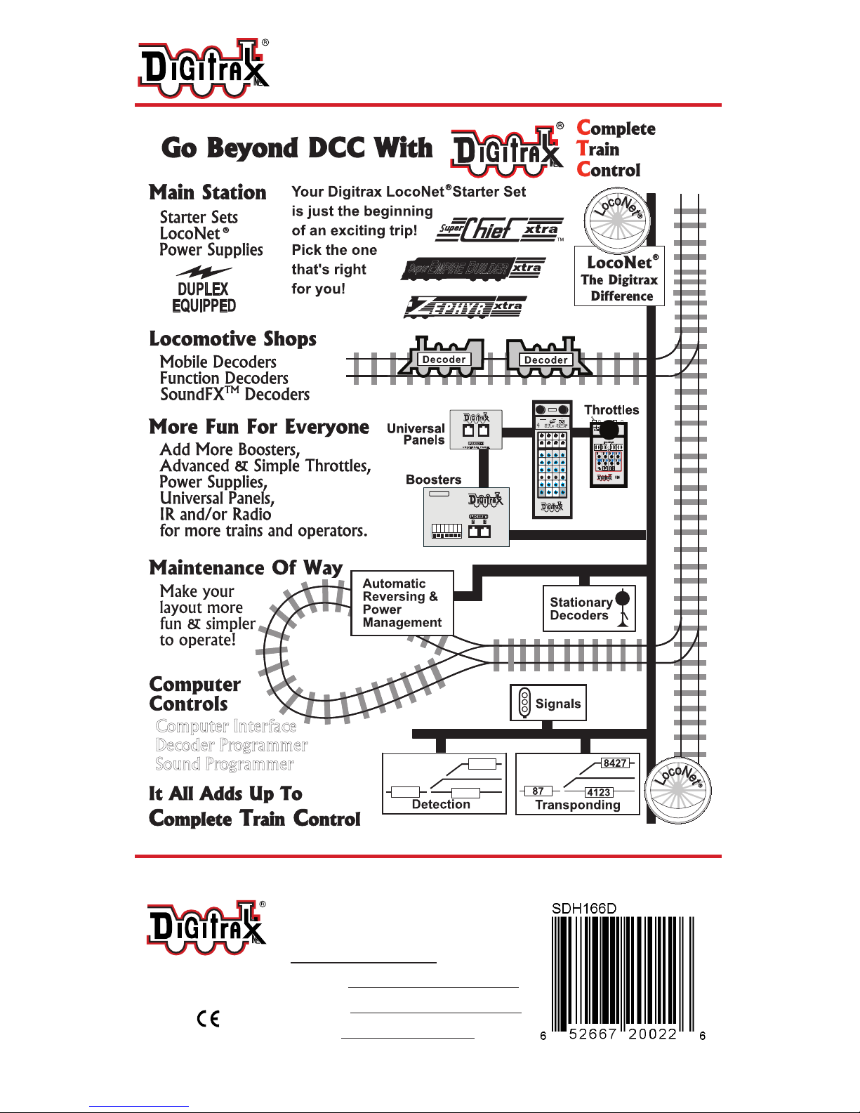
Complete Train Control
Run Your Trains, Not Your Track!

© 2013 Digitrax, Inc. www.digitrax.com— 2 —
Parts List
1 SDH166D Function Decoder with SoundFX®
1 Instruction Sheet
1 10 Pin Sound Harness - 8 Ω 16 x 26 x 9 mm box speaker and 330uF cap
1 9 Pin Digitrax easy connect Track, Motor, and Function Harness
Installation Information
See the Digitrax Decoder Manual for complete decoder test procedures, instal-
lation instructions, programming and technical information. Digitrax manuals
and instructions are updated periodically. Please visit www.digitrax.com for the
latest versions, technical updates and additional locomotive-specic installation
instructions. CAUTION: Programming and layout track must not exceed
16V when using this decoder.
Installation Instructions
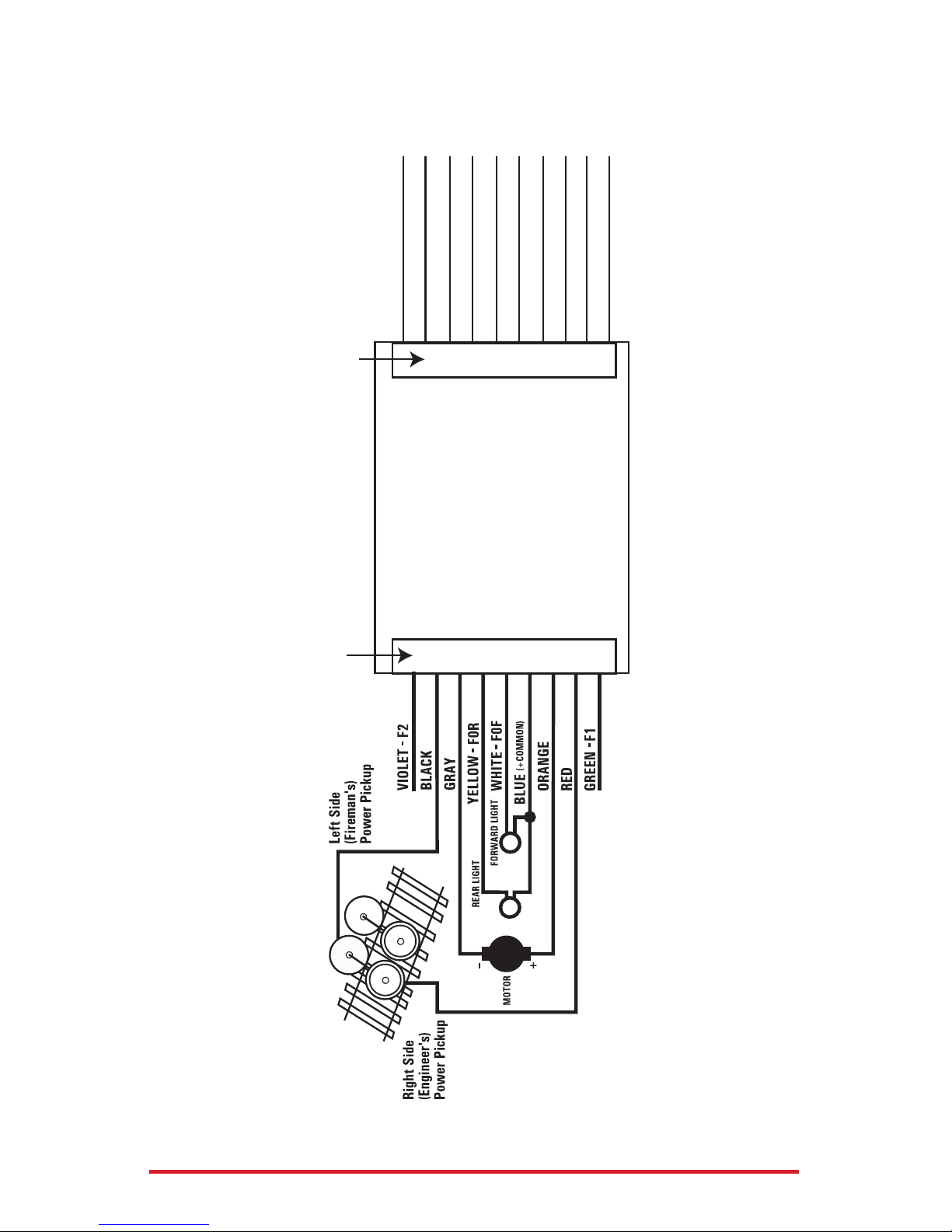
Figure 1: SDH166D Decoder Connections
SDH166D showing 10 Pin Sound Harness with 8 Ohm 16 x 26 x 9mm box
speaker and 330uF capacitor
1. On the 9 Pin Track, Motor and Function Harness solder the Red and Black
track leads to the locomotive track power connections. Next solder the
Orange and Gray motor leads to the isolated motor connections. Motor
connections must be isolated from the track connections. Note that to be
able to read back SoundFX CVs either a motor load must be connected to the
Orange and Gray leads or a combination of function loads of at least 60mA at
12volts must be connected to the function leads.
For most reliable operation
Digitrax recommends soldering
the SDXH166D connections
SDXH166D: 9 Pin
Track, Motor and Func-
tion Harness
10 Pin Sound Harness

© 2013 Digitrax, Inc. www.digitrax.com— 3 —
2. On the 9 Pin Track and Function harness connect the function leads that are
to be used for e.g. lights. Insulate any unused function leads so they cannot
short to the locomotive frame or track power.
3. Mount the factory 8 ohm 16 x 26 x 9mm box speaker attached to the 10 Pin
Sound Harness in a suitable location (refer to Figure 2). Be sure to inspect
the speaker diaphragm for magnetic debris or damage, which will affect
sound quality. Other speaker(s) may be substituted in combinations as long
as the total impedance between Pin 3 and Pin 8 of the 10 Pin Sound Harness
is 8 ohms or greater.
Depending on the locomotive model and construction it may be necessary to
modify the frame or parts of the internal shell to make room for one or more
speakers and enclosures.
4. Mount the 330uF electrolytic energy storage capacitor from the 10 Pin Sound
Harness. Be sure not to short the capacitor case or leads to the track leads or
locomotive frame or damage to the decoder may result.
5. For Steam units using external synchronization cam capability, connect the
White CAM wire of the 10 Pin sound harness to the output connection of
your cam, and congure CV133 to a value of 128 to make the steam chuff to
be synchronized with the external cam.
6. Inspect the installation before testing the sounds and replacing the shell. In
particular be sure that wires are correctly soldered and routed and that the
motor and capacitor leads are not shorted to the frame or track.
7. Place the loco on an active DCC track powered by a compatible DCC system
and select the factory default address 03 to enable sounds for testing.
8. Be sure F8 (mute) is OFF to allow sound output, and then press
F1 (bell) or F2 (whistle/horn) ON to hear the associated sounds.
9. Customize sounds by programming Sound CVs to adjust the desired cong-
urations, as shown in the following tables of SoundFX CVs. Sound schemes
other than the factory preloaded default Steam (CV60=0) or Diesel (CV60=1)
schemes can be loaded by using a Digitrax PR3 SoundFX Programmer.
Figure 2: SDH166D: Install example in Athearn SD-70MAC with 9-Pin plug
SDH166D decoder
on double sided
tape on top of
light board
Decoder wires -
formed to avoid
moving parts
Speaker
Installed
330uF
Energy
storage
capacitor

© 2013 Digitrax, Inc. www.digitrax.com— 4 —
Speaker Mounting and bafe or enclosures.
The sound performance of any attached speaker(s) is greatly affected by
the mounting system and required bafe or rear enclosure. The included
8ohm box speaker is pre-mounted in a bafe for your convenience, how-
ever additional bafes or other mounting systems may need to be taken
into consideration when installing.
The bafe is used to isolate the speaker diaphragm front sound waves
from the “out of phase” rear sound waves. This minimizes sound can-
cellation, particularly at lower frequencies. For most efcient sound
generation, the cubic volume of the bafe should be as large as practically
possible, and the bafe walls should be acoustically rigid so not to allow
acoustic interference.
Practical bafe materials are plastic, cardboard and even sheet metal.
Common items such as cardboard tubes, soda caps, or 35mm lm can-
isters may be modied and trimmed to create reasonable bafes in the
available space. Most HO or O scale or similar locomotives have limit-
ed internal volume within the shell, so the choice of speaker mounting
benets from some ingenuity to get best sound performance and space.
Of course, you can substitute an alternate after market speaker of the
maximum size for the locomotive you have.
Customizing Your Decoder
Your Digitrax SDH166D SoundFX decoder is ready to run and will
operate and generate sound using address 03 with no additional
programming. On your Digitrax system, simply select the locomotive’s
address and the sound will start. On some DCC systems, it is necessary to
select the locomotive address AND send a command to start the sounds.
For a more prototypical railroading experience, your decoder can be
customized for your specic locomotive by programming some of the
Conguration Variables, or CVs, available. Digitrax Sound decoders can
be programmed using either a programming track or with the operations
mode using the main line. See the Digitrax Decoder Manual or the Digi-
trax web site for more information.
CAUTION: Programming track must not exceed 16V when
programming this decoder.
Digitrax PS14 is the ideal power supply for the PR3.

© 2013 Digitrax, Inc. www.digitrax.com— 5 —
Initial Test and Programming: This decoder is preprogrammed and
tested with a Steam locomotive sound scheme, and is ready to operate on
factory default address 03. Before customizing the decoder it is useful to
run it on the factory default address 03 to check the installation.
The following sections show how to change the locomotive address and
customize the decoder.
For more information on general decoder installation and programming
techniques and examples visit www.digitrax.com
Changing the Decoder Address
The rst CV most people change is the decoder address. This allows
you to independently control each loco with a unique address. Digitrax
decoders are shipped with CV01 (AD2), the two digit address, set to 03.
Following is a brief description of how to change the decoder address
with a Digitrax DT4XX series throttle. See your Starter Set Manual for
complete programming instructions.
1. Place the loco on the programming track not to exceed 16V.
Go into Program Mode on your system. On DT4XX throttle press
PROG.
2. Choose AD2 for 2 digit addressing or AD4 for 4 digit addressing.
3. Choose the address you want to set up for the decoder.
4. Complete address programming by pressing ENTER.
Note: CV29 must also be programmed to enable 4 digit addressing, this
is done automatically by the DT4XX throttles. See your Digitrax Decoder
Manual or the Digitrax Toolbox App for how to set up CV29.
Using this decoder in other locomotives
The factory supplied sound project loaded into the SDH166D is for a
Steam (default) or SD38-2 diesel locomotive, selectable with the value in
CV60. If you want to install it in a different locomotive, you can simply
load a different sound project for that type of locomotive. The cam input
is available for Steam installations where you want to synchronize
chufng.

© 2013 Digitrax, Inc. www.digitrax.com— 6 —
Digitrax LocoMotion®System
Your locomotives look like the real thing, now you can make them run
like the real thing, too. Digitrax decoders incorporate torque
compensation for smooth as silk operation. You can also program CVs
that control momentum, 3 step and 128 step speed tables, switching
speed, normal direction of travel, scalable speed stabilization and more
to take full advantage of the Digitrax LocoMotion System.
Momentum-CV03 & CV04
Momentum is part of the LocoMotion System. Acceleration is controlled
by CV03 and deceleration by CV04. Both come from the factory set to
000. A range of 000 to 031 is available for both accel and decel. Try
CV03:003 and CV04:000 as a starting point for experimenting with
momentum.
Speed Tables-How the Loco Responds to the Throttle
With Digitrax LocoMotion, there are two types of speed tables: 3 Step Ta-
bles and High Resolution 28 Step Tables. Please see your Decoder Man-
ual for a discussion of the 28 Step Tables. The 3 Step Tables are set up
by programming 3 CVs: Start Voltage (CV02), Mid point Voltage (CV06)
and Max Voltage (CV05). These values are set at 000 at the factory. All
have a range of values from 000 to 255. We recommend the following CV
values as a starting point for experimenting with speed tables.
Loco Type V Start
CV02
V Mid
CV06
V Max
CV05
Switcher
Concentrated low speed. Limited top
speed
002 038 064
Road Switcher
Prototypical top speed w/evenly
distributed curve from 0 to top speed
002 048 098
Mainline Loco
Quick increase to cruising speed then
levels off to prototypical top speed.
002 128 154
Decoder Reset CV08
Decoder reset lets you reset all CV values to the initial factory settings. To
reset all CV values, program CV08 to a value of 008. You also have the
option of resetting all values except the 28 speed step tables. To do this,
program CV08 to a value of 009.

© 2013 Digitrax, Inc. www.digitrax.com— 7 —
Other LocoMotion®Features: Switching Speed, Normal
Direction of Travel & Scalable Speed Stabilization
(Back EMF) Features
Switching speed is controlled by CV54. The factory setting is 000 for
OFF. To turn on the switching speed feature, program CV54 to a value
of 001. When this feature is on, use F6 to activate and deactivate switch-
ing speed. With the feature on the throttle’s target speed is effectively
reduced by about 50% and the effects of accel and decel programmed
into the decoder are reduced by 1/4. This is useful for yard switching
operations.
Normal Direction of Travel is controlled by CV29. See your decoder
manual or the Digitrax Toolbox App for additional information on the
settings for CV29.
Digitrax SoundFX®System
Digitrax SoundFX lets you make your locos sound in scale like the real
thing! The SoundFX sound CVs in the range of CV140 to CV256 let you
customize your decoder without having to reprogram or change the
installed sound scheme. Standard decoder CVs in the range of CV01 to
CV120 operate the same as for a non-SoundFX3Digitrax decoders (they
control motor and light functions etc.) CV58 is used as Master Volume,
and CV60 is used to select an alternate scheme, if provided in the sound
project. Sound CV155 is provided to select Diesel engine “notching”
modes. The default of CV155=00 provides “automatic notching” that
changes the diesel RPM settings at 8 distinct throttle speeds that are
controlled by Sound CV132. Sound CV155=01 selects “semi-automatic
notching” mode that allows F6 ON to increase the notch from the current
throttle setting and F7 ON to decrease back towards the lowest current
throttle notch setting. Sound CV155=02 selects “manual notching” mode
that allows F6 ON to increase the notch setting and F7 ON to decrease
the notch setting irrespective of the throttle setting, which controls just
the motor speed. The decoder’s sound scheme can be reloaded using a
Digitrax PR3 programmers and a sound project le from the Digitrax
Sound Depot on our web site. Typical sound downloads take between 50
and 100 seconds depending on the project complexity and le size. The
following tables show the CVs used in this decoder version and how it is
set up at the factory to operate various sounds using your throttle

© 2013 Digitrax, Inc. www.digitrax.com— 8 —
CV# Used For Range Default
Value
01 2 Digit Address 03
11
Sound Time Out, 06 = Sound ends when loco ad-
dress is de-selected, 00=Sound stays on after loco is
de-selected
06
29
Conguration Register - Advanced or Standard
speed steps, 2 or 4 digit addressing, Analog Mode,
Normal direction of travel, speed tables
06
49 Forward Light (FOF) - Headlight 00
50 Reverse Light (FOR) - Reverse Light 00
51 Function 1 00
52 Function 2 00
58 Master Volume (F8 used for Mute) 1=min 00=max 00-15 09
60 Scheme 0=Steam 1=GP38 Diesel 00-01 00
132 Notch Rate 00-255 127
133 Steam Chuff/CAM cong, 128=>EXT cam,
1-127=>DRIVER dia in inches 01-128 63
134 Steam Gear Ration Trim, 32 = 100% Ratio 00-255 32
135 Mute Volume 00-64 00
140 Prime Mover / Chuff Volume 00-64 60
141 Bell Volume 00-64 25
142 Horn/Whistle Volume 00-64 60
143 Time-Scattered Air Effects Volume 00-64 30
145 Misc Vols 00-64 40
146 Bell Ring Rate (1=24 milliseconds) 01-100 07
147 Air Drier Rate (1-about 2 seconds) 01-64 02
148 Compressor Run Rate 00-255 30
149 Air Compress On Time 00-255 20
150 Horn/Whistle Setup (Default=0, Playable Horn=1,
Alternate Horn=2 +128 for playable volume.)
00-07 or
128-135 00
151
Auto Coupler Sequence Threshold Value-Peak speed
to allow auto coupler/brake when direction change
occurs and F3 is ON
00-64 48
152 Project Author ID, Digitrax=221 221
153 Project ID, Steam/SD38_2 02
154 Steam Blow down / Safety Volume 0-64 60
155 Notching/Slip Mode: 00=Automatic, 00

© 2013 Digitrax, Inc. www.digitrax.com— 9 —
Function Used For Notes
F0 Lights
F1 Bell
F2 Horn/Whistle CV150 sets mode
F3 Coupler crash Auto coupler/brake set
by CV151 max speed
F4 Air feature disable F4 off enables pop-off,
drier and starts com-
pressor/airpump
F5 Diesel = Dynamic brake
Fans Steam = Water
Pump turbine
F6 Diesel = Notch Up
Steam = Blowdown
Notch UP if CV155=01 or
02
F7 Crossing Gate Airhorn
or;
Diesel = Notch DOWN
Steam = Wheelslip
Notch DOWN, if
CV155 = 01 or 02
(Crossing Gate active
if in Diesel mode and
CV155=0)
F8 Mute Control F8 ON is mute
F9 Brake squeal
F10 Crossing Gate
Airhorn Sequence
F11 Steam = Greaser
F12 Steam = Safety Blowoff
SoundFX DC Operation Mode
Digitrax SoundFX decoders will operate on smooth DC power. The sound
will not start until approximately 7 volts is applied to the track and there
will be no “start up sound.”

© 2013 Digitrax, Inc. www.digitrax.com— 10 —
SDH166D Troubleshooting
If the sound does not start in the decoder
1. Make sure you have selected the locomotive address on a throttle. The sound
will not run unless the locomotive is addressed in the system.
2. Check your installation to make sure the decoder is installed properly.
If the sound output sounds distorted
1. Check the speaker cone for magnetic debris that may have collected there.
Debris on the speaker will cause a loss of sound quality and must be re-
moved.
2. Be sure that the CV58 volume is not set at a level that is too high for the
speaker being used.
If the sound in your decoder shuts down after you stop it and you are
not using a Digitrax system for control. On some DCC systems decoders
are not addressed by DCC packets after the locomotive is set to 0 speed. In this
case after the CV11 timeout elapses (6 second default), sound will “shutdown.”. To
defeat this feature, set CV11=00 to remove the timeout and shutdown. To make
sounds, the decoder must have a command addressed to it at least once.
If you have trouble reading back CVs on the programming track, this
may be due to insufcient current draw. Of course you can always just re-pro-
gram the CV value into a CV to get the desired results, even if reading CVs does
not work. OPS mode is recommended for writing to (programming) all CVs ex-
cept CV01, CV17 & CV18 (2 digit and 4 digit addresses). If a second DCC decoder
is present that is not SoundFX compatible then correct read back of CV data is
not possible, since the NMRA CV read back was not designed for multiple decod-
er read back.
The SDH166D plays a Diesel scheme, but I want the Steam scheme.
If the factory scheme has not been erased, program CV60 to a value of 0 to
reselect the Steam scheme. Alternatively set CV60 to 01 to change to the SD38-2
sound scheme.
I have loaded a new scheme but the CVs and Functions are not what
I expected. Load the sound project you programmed and then select the
view>project description” menu and then read the text le on the screen that de-
nes how that project in particular uses CVs and functions for sound generation
and conguration.
Warranty & Repair
Digitrax gives a one year “No Worries” Warranty against manufacturing defects
and accidental customer damage on all Digitrax command stations, boosters,
throttles, decoders, power supplies and layout control devices.
That’s it! A simple, straightforward warranty with no tricky language!
Visit www.digitrax.com for complete warranty details and instructions for
returning items for repair.
Please return warranty items directly to Digitrax - DO NOT return items
to place of purchase.
© 2013 Digitrax, Inc. www.digitrax.com— 11 —
SDH166/SDXH166
10 Pin Sound Harness
Pin 1 – Brown – F3
Pin 2 – Red – Not used
Pin 3 – Red – speaker (+ polarity)
Pin 4 –Yellow – F4
Pin 5 – Green – not used
Pin 6 – Blue – to sound cap +
Pin 7 – Violet – not used
Pin 8 – Black – speaker (– polarity)
Pin 9 – White – cam input (steam)
Pin 10 – Black – to sound cap -
9 Pin Digitrax Easy Connect Track, Motor
and Function Harness
PIN 1
PIN 2
PIN 3
PIN 4
PIN 5
PIN 6
PIN 7
PIN 8
PIN 9
Figure 3: SDH166D: connection diagram
Available
Computer Interface
Decoder Programmer
Sound Programmer
TM
E
MPIRE
B
UILDER
Super
TM
0 0 0 0
Made in the USA
2443 Transmitter Road
Panama City, FL 32404
www.digitrax.com
Contact: www.digitrax.com/contact
Repair: [email protected]
SDH166D
Wired Sound + Motor + Function Decoder for HO scale
locomotives
Table of contents


