Distech Controls EC-Net EC-SEC-EN-MED Manual

Medium & Large Enclosure Security
Hardware Installation Guide
Medium & Large Enclosure Security Hardware Installation Guide
Part Number 05DI-HIENCML-13 Updated: January 2014 1
Information and specifications published here are current as of the date of publication of this document. Distech Controls, Inc. reserves the right to change or
modify specifications without prior notice. The latest product specifications can be found by contacting our corporate headquarters. Products or features con-
tained herein may be covered by one or more U.S. or foreign patents. NiagaraAX Framework is a trademark of Tridium Inc. © 2009 - 2013 Distech Controls,
Inc.
This document covers the mounting and wiring of the medium and large-sized EC-NetAX Security Enclosuress
used for housing the EC-BOS-602AX Security or EC-BOS-616AX Security controller (EC-BOS-nAX Security),
and/or its expansion modules. It assumes that you are an engineer, technician, or service person who is
performing access system design or installation. Instructions apply to the following enclosure models:
Models Description Thumbnails
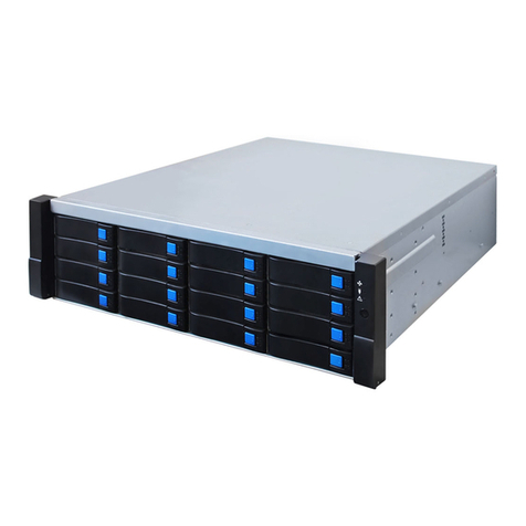
EC-SEC-EN-MED Medium-sized enclosure with single DIN rail, integral
power supply, tamper switch, key lock, and capacity for
two user-supplied 12V sealed lead-acid backup
batteries.
Accommodates the EC-BOS-nAX Security controller or 2
Remote Reader modules, or one Remote IO Security
module.
EC-SEC-EN-MNP As above, but without the integral power supply.
Accommodates one additional Remote Reader module.
EC-SEC-EN-LRG Large-sized enclosure with two (2) DIN rails, integral
power supply, tamper switch, key lock, and capacity for
two user-supplied 12V sealed lead-acid backup
batteries.
Accommodates the EC-BOS-nAX controller with up to 4
Remote Reader modules, or the EC-BOS-nAX controller
with up to 2 Remote IO Security modules, or many other
possible combinations.
EC-SEC-EN-LNP As above, but without the integral power supply.
Accommodates one additional Remote Reader module.
These are the main topics included in this document:
• Preparation, page 2
• Precautions, page 3
• Related Documentation, page 3
• Installation Summary, page 4
• Pre-Installation, page 4
• Mounting and Dimensions, page 6
• Earth Grounding and Power Wiring, page 8
–
EC-SEC-EN-MED and EC-SEC-EN-LRG
Ground and Power Wiring, page 8
–
EC-SEC-EN-MNP and EC-SEC-EN-LNP
Ground Wiring, page 9
• Backup Batteries, page 10
• Knockout Locations, page 11
• Replacement Parts, page 12
All enclosures are NEMA type 1, with UL 294 Listing.
NOTE:
•Separate documents cover the mounting and wiring
of EC-BOS-602AX Security and EC-BOS-616AX
Security controller and Remote Reader and Remote
IO Security expansion modules. Also, mounting
instructions for another small enclosure
(ENC-SEC-EN-SML) is in a separate document. See
“Related Documentation,” page 3.
•All certifications and listing information related to an
EC-BOSAX Security system can be found in the
EC-BOS-602/616AX Security Hardware Installation
Guide document.
EC-SEC-EN-MED EC-SEC-EN-MNP
EC-SEC-EN-LRG EC-SEC-EN-LNP
3TBZ 3TBZ
SECURITY

Medium & Large Enclosure Security Hardware Installation Guide
Updated: January 2014 Part Number 05DI-HIENCML-13
Preparation
Included in this Package
2
Preparation
Unpack the enclosure unit and inspect the contents of the package for damaged or missing components. If
damaged, notify the appropriate carrier at once and return any damaged components for immediate repair or
replacement. See “Returning a Defective Unit” in the EC-BOS-602/616AX Security Hardware Installation Guide.
See the following sections: “Included in this Package” and “Material and Tools Required.”
Included in this Package
Included in this package you should find the following items:
• A medium (EC-SEC-EN-MED or EC-SEC-EN-MNP) or large (EC-SEC-EN-LRG or EC-SEC-EN-LNP)
metal enclosure with removable hinged door, containing these pre-installed items:
–
35mm DIN rail, either one (1) or two (2), depending on enclosure model.
–
1/4-turn door lock, with two keys.
–
(EC-SEC-EN-MED or EC-SEC-EN-LRG models only): a universal 90–263 Vac input, 15Vdc output,
30W power supply module (EC-NPB-PWR-UN), mounted on left side of top DIN rail, pre-wired to a
3-position terminal strip.
• An enclosure installation kit, containing the following items:
–
a hardware bag containing a door tamper switch with two wire leads, a door grounding wire, various
screws, hex nuts, and cable ties.
–
if Large, a 6-conductor cable harness to connect assemblies between the two DIN rails.
–
(used in EC-SEC-EN-MED or EC-SEC-EN-LRG models only): battery wiring harness with two pairs
of 0.25" (6.35mm) spade lug connectors. (Note: battery harness to be used only if the
EC-SEC-EN-MED or EC-SEC-EN-LRG enclosure will contain an EC-BOS-nAX controller).
• This Medium and Large Enclosure Hardware Installation Guide, Part Number 05DI-HIENCML-13.
Material and Tools Required
The following supplies and tools are required for installation:
• Suitable tools and supplies for mounting enclosure, EC-BOS-nAX and expansion modules, and for making
all wiring terminations.
• (EC-SEC-EN-MED or EC-SEC-EN-LRG models only): If installing an EC-BOS-nAX controller in the
enclosure, one or two 12V sealed-lead-acid (SLA) backup batteries, as required by the system. See the
EC-BOS-602/616AX Security Hardware Installation Guide section “Estimating Power and Battery
Requirements” for details on calculating battery requirements.
The included wiring harness is designed for common 12V sealed lead-acid (SLA) batteries that have 0.25"
(6.35mm) wide “fast on” battery terminals. Overall dimensions of commonly used batteries are 5.96”
(150mm) long x2.56” (65mm) wide x3.84" high.
Example models of such batteries include:
–
Yuasa NP7-12 – 12V 7Ahr
–
Panasonic LC-R127R2P1 – 12V 7.2 Ahr

Precautions
Safety Precautions
Medium & Large Enclosure Security Hardware Installation Guide
Part Number 05DI-HIENCML-13 Updated: January 2014 3
Precautions
This document uses the following warning and caution conventions:
Caution Cautions remind the reader to be careful. They alert readers to situations where there is a chance
that the reader might perform an action that cannot be undone, might receive unexpected results,
or might lose data. Cautions contain an explanation of why the action is potentially problematic.
Warning Warnings alert the reader to proceed with extreme care. They alert readers to situations
where there is a chance that the reader might do something that can result in personal injury
or equipment damage. Warnings contain an explanation of why the action is potentially
dangerous.
Safety Precautions
The following items are warnings relating to the power supply wiring to a Security Enclosures. Be sure to heed
these warnings to prevent personal injury or equipment damage.
Warning • The circuit powering the Security Enclosures power supply is from 120 to 240Vac at
50/60 Hz. Disconnect power before installation or servicing to prevent electrical shock
or equipment damage.
• Make all connections in accordance with national and local electrical codes. Use copper
conductors only.
• To reduce the risk of fire or electrical shock, install in a controlled environment relatively
free of contaminants.
• This system is only intended for use as a monitoring and control device. To prevent data
loss or equipment damage, do not use it for any other purpose.
Related Documentation
For more information on mounting and wiring a EC-NetAX Security system, refer to the following documents:
• EC-BOS-602/616AX Security Hardware Installation Guide
• Remote 2 Reader Module (Remote Reader) Hardware Installation Guide
• Remote I/O Module (Remote IO Security) Hardware Installation Guide
• Small (ENC-SEC-EN-SML) Security Enclosure Install Sheet
For details on software configuration for a fully functioning security system, refer to the following document:
• EC-NetAX Security Guide

Medium & Large Enclosure Security Hardware Installation Guide
Updated: January 2014 Part Number 05DI-HIENCML-13
Installation Summary
Removing and replacing the enclosure door
4
Installation Summary
Installation of the medium or large Security Enclosures is covered in the following main sections:
• Pre-Installation, page 4
• Mounting and Dimensions, page 6
• Earth Grounding and Power Wiring, page 8
• Backup Batteries, page 10
After completing these tasks, please refer to the appropriate “Hardware Installation” Guide for the EC-NetAX
Security equipment that you are installing in the enclosure. For example, refer to the EC-BOS-602/616AX
Security Hardware Installation Guide. See Related Documentation, page 3.
Pre-Installation
The following pre-installation tasks are explained:
• Removing and replacing the enclosure door
• Locate and remove enclosure knockouts
• Install the door tamper switch
• Locate and mark mounting holes
Removing and replacing the enclosure door
The door on a Security Enclosures is removable. It is often convenient to remove the enclosure door before
other mounting and wiring tasks. This also provides a lighter unit for initial mounting to the wall.
Procedure 1 Removing the door of a Security Enclosures.
Step 1
Open (and if necessary, unlock) the door, opening it about half way.
Step 2
Slide the door toward the top of the unit, until the hinge tabs on the door clear the hinge pins on the
enclosure.
Step 3
Lift the door away from the enclosure.
Procedure 2 Replacing the door of a Security Enclosures.
Step 1
Align the hinge tabs on the door above the hinge pins on the left wall of the metal casing.
Step 2
Slide the door toward the bottom of the unit, until the door hinge tabs fully seat onto the hinge pins.
Step 3
Close the door and check for proper fit.

Pre-Installation
Locate and remove enclosure knockouts
Medium & Large Enclosure Security Hardware Installation Guide
Part Number 05DI-HIENCML-13 Updated: January 2014 5
Locate and remove enclosure knockouts
The Security Enclosures has numerous knockouts on the top, sides, and bottom (see figure on page 11). Locate
and remove any knockouts required for conduit and cabling entering the unit, before mounting it to the wall. In
addition, install the appropriate conduit or cable clamps to the removed knockouts.
Note Conduit must be used for all AC power wiring, with conduit clamps installed in enclosure knockouts.
Procedure 3 Locate and remove enclosure knockouts.
Step 1
Depending on which direction the conduit and cabling will be brought to the enclosure, remove the
appropriate knockouts.
Step 2
Install the appropriate conduit or cable clamps in the knockout holes.
Install the door tamper switch
The Security Enclosures has a door “tamper switch” that mounts in an enclosure tab near the top of the door
opening (see Figure 1). Use the two sheet metal screws (provided) to fasten the switch.
Figure 1 Tamper switch installation.
Procedure 4 Install the door tamper switch.
Step 1
Thread the two leads of the tamper switch through the front of the hole in the mounting tab.
Step 2
Fasten the switch to the tab using the provided Phillips-head sheet metal screws.
Notes • The two tamper switch leads will be connected (later) to the EC-BOS-nAX controller or one of its
expansion modules, depending on the system. For now, move the switch leads neatly away to avoid
being harmed.
• Later, after reinstalling the enclosure door, check the adjustment screw on the tamper switch. You
may need to tighten or loosen the adjustment screw for proper switch operation.
Tamper
Switch
Leads
Mounting
Tab
Door Tamper Switch
with
Adjustment Screw
Fasten switch to
mounting tab
using 2 provided
screws.

Medium & Large Enclosure Security Hardware Installation Guide
Updated: January 2014 Part Number 05DI-HIENCML-13
Mounting and Dimensions
Locate and mark mounting holes
6
Locate and mark mounting holes
The Security Enclosures has four main mounting holes on its back wall—the upper two holes are keyhole types.
It is often convenient to mark the location of the mounting holes in the wall before continuing.
Procedure 5 Locate and mark enclosure mounting holes.
Step 1
With the enclosure door opened or removed, position the enclosure on the wall in the location where
it will be installed.
Note For locations and dimensions of enclosure mounting holes, see Figure 2 on page 7 for medium
sized enclosures (EC-SEC-EN-MED, EC-SEC-EN-MNP) and Figure 3 on page 7 for large sized
enclosures (EC-SEC-EN-LRG, EC-SEC-EN-LNP).
Step 2
Carefully mark the mounting hole locations, and remove the enclosure.
Step 3
Drill the needed pilot holes in the wall, for example to install wall anchors (if needed), and install wall
anchors if used. For example, drill 5/16" (8mm) holes for wall anchors.
Mounting and Dimensions
Note Mount the Security Enclosures in an indoor location only. For more environmental requirements, see
the “UL Requirements” section in the EC-BOS-602/616AX Security Hardware Installation Guide.
Following pre-installation tasks, the enclosure is ready for wall mounting. Install fasteners in all 4 mounting
holes, tightening securely. For example, if wall anchors were installed in 5/16" holes, use four #14 anchor bolts,
or other appropriate fasteners, as needed to securely fasten.
• See Figure 2 on page 7 for medium enclosure (EC-SEC-EN-MED, EC-SEC-EN-MNP) wall mounting
dimensions.
• See Figure 3 on page 7 for large enclosure (EC-SEC-EN-LRG, EC-SEC-EN-LNP) wall mounting
dimensions.
After mounting, replace the enclosure door if removed, see
“Removing and replacing the enclosure door,”
page 4.
Note A short, green, grounding wire with ring ends is included in the enclosure’s hardware bag. After
mounting and final replacement of the door, install this wire on the studs inside the door and on the
enclosure’s left side, near the lower hinge. Use the included #6-32 keps nuts to fasten the wire ends to
the studs. For the location of this grounding wire, see Figure 2 and Figure 3 on page 7.

Mounting and Dimensions
Locate and mark mounting holes
Medium & Large Enclosure Security Hardware Installation Guide
Part Number 05DI-HIENCML-13 Updated: January 2014 7
Figure 2 EC-SEC-EN-MED, EC-SEC-EN-MNP medium enclosure wall mounting details.
Figure 3 EC-SEC-EN-LRG, EC-SEC-EN-LNP large enclosure wall mounting details.
2.5"
(63.5)
8.25"
(209.6)
2 x
0.219"
(5.56)
0.88"
(22.4 )
R. 0.110"
(2.8)
0.438" (11.1)
0.406"
(10.3)
0.19"
(4.83)
17.0"
(431.8)
15.0"
(381.0)
15.0"
(381.0)
1.0" (25.4)
4.265"
(108.2 )
overall depth
including door
NOTE: All dimensions given
in " inches and (mm).
EC-SEC-EN-MED
EC-SEC-EN-MNP
Door grounding
wire (install)
15.0"
(381.0)
3.5"
(88.9)
14.25"
(362.0)
1.0"
(25.4)
2 x
0.219"
(5.56 )
0.88"
(22.4)
R. 0.110"
(2.8 )
0.438" (11.1)
0.406"
(10.3)
0.19"
(4.83)
17.0"
(431.8)
22.0"
(558.8)
NOTE: All dimensions given
in " inches and (mm).
EC-SEC-EN-LRG
EC-SEC-EN-LNP
Door grounding
wire (install) 4.265"
(108.2 )
overall depth
including door

Medium & Large Enclosure Security Hardware Installation Guide
Updated: January 2014 Part Number 05DI-HIENCML-13
Earth Grounding and Power Wiring
EC-SEC-EN-MED and EC-SEC-EN-LRG Ground and Power Wiring
8
Earth Grounding and Power Wiring
The Security Enclosures must be connected to a nearby earth ground.
• If a unit with an integral power supply, wire ground to the unit’s 3-position terminal strip, along with power
wiring. See the next section “EC-SEC-EN-MED and EC-SEC-EN-LRG Ground and Power Wiring”.
• If a unit without an integral power supply, make an earth ground connection to a designated grounding
stud inside the enclosure. See “EC-SEC-EN-MNP and EC-SEC-EN-LNP Ground Wiring,” page 9.
EC-SEC-EN-MED and EC-SEC-EN-LRG Ground and Power Wiring
The integral power supply in a EC-SEC-EN-MED or EC-SEC-EN-LRG enclosure provides 30W of regulated
15Vdc power to a EC-BOS-nAX and/or its connected expansion modules. Input voltage is 120Vac to 240Vac,
single phase.
Warning A 120Vac or 240Vac circuit powers the Security Enclosures power supply. Disconnect power
to this circuit before installation to prevent electrical shock or equipment damage.
Caution • AC power wiring must be routed in conduit. AC power cords routed through cable clamps are
not permitted.
• Size power conductors in accordance with the local regulating authority, such as the NEC.
• Do not exceed the 30W supply capacity of the Security Enclosures power supply by the
powered devices. Door strike power, as well as power for other loads switched by the
EC-BOS-nAX and/or its expansion modules, should always be provided from a different
source.
Figure 4 Wire AC power circuit with ground to 3-position terminal strip (pre-wired to power supply).
Wire to top of
3-position
terminal strip
LN
Power supply is pre-wired to
bottom of terminal strip.
GROUND
NEUTRAL
LINE
LN
Power supply
to provide
15Vdc, 30W
6-position connector
If EC-BOS-nAX
controller is in
enclosure, mount it
here to attach directly to
power supply.

Earth Grounding and Power Wiring
EC-SEC-EN-MNP and EC-SEC-EN-LNP Ground Wiring
Medium & Large Enclosure Security Hardware Installation Guide
Part Number 05DI-HIENCML-13 Updated: January 2014 9
Procedure 6 (EC-SEC-EN-MED or EC-SEC-EN-LRG only) Power and ground wiring.
Step 1
Remove power from the AC circuit being wired to the Security Enclosures power supply—see
previous Warning on page 8.
Step 2
Route the AC circuit wiring (Line, Ground, Neutral) through conduit in the top left area of the enclosure,
and terminate to the 3-position terminal strip. See Figure 4 on page 8.
Note Do not remove the plastic cover of the power supply. The power supply is pre-wired to the
3-position terminal strip, along with the enclosure chassis.
Step 3
Before restoring power to the Security Enclosures power supply, complete any other wiring
connections on the EC-BOS-nAX and its accessory modules.
Note 15Vdc output power is provided on the 6-position connector of the power supply. If installing an
EC-BOS-nAX controller, you mount it on the top DIN rail in the enclosure, plugged directly into the power
supply connector. If the enclosure contains only expansion modules, you populate the top DIN rail first.
If installing a model EC-SEC-EN-LRG enclosure, note the included 6-wire harness that supplies 15Vdc power
and communications to any modules you mount on the lower DIN rail.
EC-SEC-EN-MNP and EC-SEC-EN-LNP Ground Wiring
For units without an integral power supply, wire earth ground to the enclosure as described below.
Procedure 7 Grounding the EC-SEC-EN-MNP or EC-SEC-EN-LNP enclosure.
• Wire earth ground to the enclosure, using a minimum 14 AWG (2.5mm2cross section) wire attached to a
designated grounding stud inside the enclosure.
14 AWG minimum
(2.5mm2cross section).
Enclosure
Stud
Wire earth
ground to
stud inside
enclosure.

Medium & Large Enclosure Security Hardware Installation Guide
Updated: January 2014 Part Number 05DI-HIENCML-13
Backup Batteries
EC-SEC-EN-MNP and EC-SEC-EN-LNP Ground Wiring
10
Backup Batteries
If the EC-SEC-EN-MED or EC-SEC-EN-LRG enclosure will house an EC-BOS-nAX controller, after mounting it
you can use the bottom of the enclosure to place one or two 12V sealed lead-acid backup batteries. See
Figure 5 for an example of locating two batteries.
Note Maintain a minimum 1/2 in.(13mm) spacing between battery leads and power-limited wiring.
Figure 5 (EC-SEC-EN-MED or EC-SEC-EN-LRG only) mounting 12V backup batteries--applies only if EC-BOS-nAX
controller.
See the “Material and Tools Required” section on page 2 for more details about backup batteries.
Caution Before connecting the 12V backup battery(ies) to the supplied backup battery wires, remove the
corresponding 4-position connector from the EC-BOS-nAX controller, and wire the pre-stripped
leads of the battery wires into the “BT+” and “BT-” terminals of that connector, observing the proper
polarity. Otherwise, connecting the battery(ies) to these wires may result in a short. For related
details, see “Connect the Backup Battery” in the EC-BOS-602/616AX Security Hardware Installation
Guide.
12V 7A-hr
Backup
Battery(ies)
Wire harness
(2 pieces) for
connecting
batteries
Bottom of EC-SEC-EN-MED or EC-SEC-EN-LRG enclosure

Knockout Locations
EC-SEC-EN-MNP and EC-SEC-EN-LNP Ground Wiring
Medium & Large Enclosure Security Hardware Installation Guide
Part Number 05DI-HIENCML-13 Updated: January 2014 11
Knockout Locations
Figure 6 provides the locations of knockouts in both the Medium and Large enclosure models. Two knockout
sizes are used: 0.95" (24.1mm) - for 1/2" conduit, and 1.20" (30.5mm) - for 3/4" conduit.
Figure 6 Knockout numbers and locations for Medium and Large enclosures.
(2)
(1) 1/2" Conduit
Knockouts
(1)
(1)
1/2" Conduit Knockout (center)
3/4" Conduit
Knockouts
3/4" Conduit Knockout (center)
1/2” Conduit
Knockouts:
To p : 3
Left Side: 2
Right Side: 2
Bottom: 1
3/4” Conduit
Knockouts:
Top: 3
Left Side: 2
Right Side: 2
Bottom: 1
1/2” Conduit
Knockouts:
Top: 3
Left Side: 3
Right Side: 3
Bottom: 1
3/4” Conduit
Knockouts:
Top: 3
Left Side: 3
Right Side: 3
Bottom: 1
EC-SEC-EN-MED or EC-SEC-EN-MNP
(1)
EC-SEC-EN-LRG or EC-SEC-EN-LNP
1/2" Conduit Knockout (center)
(1)
(2)
(1)
(1)
(1)
(1)
1/2" Conduit
Knockouts
(1)
(2)
(1)
(1)
(1)
(2)
(1)
(1)
(1)
(1)
3/4" Conduit Knockout (center)
(1)
3/4" Conduit
Knockouts
(1)
(1)

Distech Controls Inc.
www.distech-controls.com
05DI-HIENCML-13
05DI-HIENCML-13
Replacement Parts
Standard replacement parts are listed in Table 1 and can be ordered from stock without restriction. Standard
replacement parts cannot be returned for credit and should be disposed of in an appropriate manner.
Table 1 Standard replacement parts.
Part Number Description
07CBL-TR10763 6-conductor wiring harness used between assemblies on the top and bottom DIN rails in the large size
(EC-SEC-EN-LRG or EC-SEC-EN-LNP) security enclosure.
07CBL-TR10764 Battery wiring harness.
06KEY-TR10765 Enclosure door key lock with 2 keys.
06SWT-TR10781 Replacement tamper switch.
EC-NPB-PWR-UN Only for EC-SEC-EN-MED or EC-SEC-EN-LRG enclosures with integral power supply: DIN-mountable
30W, 15Vdc power supply.
This manual suits for next models
3
Table of contents
