Dive Lab XLDS RDC-3 User manual

© Copyright 2003-2019 Dive Lab® Inc. All rights reserve .
This Gui e is ma e available for the express use of owners an users of the Dive Lab XLDS systems.
This information is subject to perio ic up ates an changes. Always check the Dive Lab web site for the latest versions.
Document XLDS Gui e
Revise August 21, 2019
EXTREME LIGHTWEIGHT DIVING SYSTEM
RAPID DEPLOYMENT CONSOLE
(XLDS RDC-3 AND RDC-2)
MAINTENANCE MANUAL
Dive Lab, Inc.
1415 Moylan Roa , Panama City Beach, FL 32413
Phone: 850-235-2715 Fax: 850-235-0858 E-mail: ivelab@ ivelab.com

TABLE OF CONTENTS
© Copyright 2003-2019 Dive Lab® Inc. All rights reserve .
This Gui e is ma e available for the express use of owners an users of the Dive Lab XLDS systems.
This information is subject to perio ic up ates an changes. Always check the Dive Lab web site for the latest versions.
Document XLDS Gui e / Table of Contents
Revise July 17, 2019
SECTION ONE: GENERAL INFORMATION Pages
Definitions 1
A vantages 2
User Gui e 2
SECTION TWO: CONCEPT AND INTENDED USE
Interme iate Surface Supply Concept 3
Conventional Surface Supplie Diving 3
XLDS Major Subsystems 4
High Pressure Supply 5
SECTION THREE: CONFIGURATION AND USE
Air Control Console 6
XLDS System Restrictions 6
Ultra Light Umbilicals 7
Communication Strength Member 7
Pneumofathometer Hose 7
Grab Line 7
Diver Worn Harness an Manifol Compensating System 7
XLDS-RDC-3 Specifications 8
Surface Supply Console Flow Capability 8
Work of Breathing Performance 8
High Pressure Air System 9
Diver Interme iate Compensating Manifol Gas Flow 9
Emergency Gas System 10
SECTION FOUR A: REPAIR, MAINTENANCE AND OVERHAUL PROCEDURES
General Cleaning / Inspection Proce ures 11
Pipe Threa s 11
Checking & Quantifying Leaks 12
Torque Tightening 13
RDC Regulator 13
Low Pressure Umbilical Supply Valves/Cross-Connect Valves 18
Check Valve/One-Way Valve 21
Pneumofathometer Valve Lubrication 24
High Pressure Supply Valve 26
Relief Valve 29
Hylock SS Angle Relief Overhaul 32
ICS Regulator Assy / Components Overhaul 34
Cleaning/Inspection of the ICS Regulator 36
EGS Valve Cleaning an Overhaul 37

TABLE OF CONTENTS
© Copyright 2003-2019 Dive Lab® Inc. All rights reserve .
This Gui e is ma e available for the express use of owners an users of the Dive Lab XLDS systems.
This information is subject to perio ic up ates an changes. Always check the Dive Lab web site for the latest versions.
Document XLDS Gui e / Table of Contents
Revise July 17, 2019
SECTION FOUR A: REPAIR, MAINTENANCE AND OVERHAUL PROCEDURES
continue Pages
ICS Testing 40
System Flow Test 41
One-way Valve Cleaning / Overhaul 42
Cleaning / Inspection of the ICS Manifol Block 43
Cleaning / Inspection of the Dive Lab Integrate Harness with Buoyancy Wing 47
SECTION FOUR B: REPAIR, MAINTENANCE AND OVERHAUL PROCEDURES
XLDS System Pressure Gauge Comparison 50
Submersible Pressure Gauges 50
ICS 300 psig Interme iate Test Gauge 51
XLDS System Pressure Test Proce ure 51
XLDS Annual Relief Valve Lift Check 51
SUPPLEMENTAL INFORMATION
Explo e View for Aqua Environment Regulator 52
XLDS O-Ring Chart 53

© Copyright 2003-2019 Dive Lab® Inc. All rights reserve .
This Gui e is ma e available for the express use of owners an users of the Dive Lab XLDS systems.
This information is subject to perio ic up ates an changes. Always check the Dive Lab web site for the latest versions.
Document XLDS Gui e
Revise July 17, 2019
Definitions of Signal Wor s
Use in this User’s Gui e
CAUTION
This wor in icates a potentially hazar ous
situation, which if not avoi e , may result in
minor or mo erate injury. It may also be use to
alert against unsafe practices.
WARNING
This wor in icates a potentially hazar ous
situation, which if not avoi e , coul result in
eath or serious injury.
DANGER
This wor in icates an imminently hazar ous
situation, which if not avoi e , will result in
eath or serious injury.
NOTICE
This wor in icates a special attention or
require action for basic operation.

© Copyright 2003-2019 Dive Lab® Inc. All rights reserve .
This Gui e is ma e available for the express use of owners an users of the Dive Lab XLDS systems.
This information is subject to perio ic up ates an changes. Always check the Dive Lab web site for the latest versions.
Document XLDS Gui e – Section One
Revise July 17, 2019
1
SECTION ONE: GENERAL INFORMATION
General Information
The Extreme Lightweight Diving System (XLDS), is
a combination of assemblies an components,
esigne an engineere as a complete surface
supplie iving system, allowing for rapi set-up
an eployment. The System was esigne an
engineere by Dive Lab, Inc., primarily for Military
an Paramilitary use, an is inten e to meet
specific performance goals an engineering
requirements. The XLDS is available in two
mo els, the XLDS-RDC-2 (two (2) iver) an XLDS-
RDC-3 (three (3) iver). Both the two an three
iver Systems, consist of four major sub
assemblies, that work as a complete iver supply
system, primarily inten e an esigne for use
with Kirby Morgan Helmets an Full Face Masks,
but will also work with other eman mo e
equipment, as outline in the User Gui e.
Definitions
RDC-2: Rapi eployment, 2 Diver Control
Console
RDC-3: Rapi Deployment, 3 Diver Control
Console
XLDS: Extreme Lightweight Diving System
ICS: Interme iate Compensating System
SCUBA: Self Containe Un erwater Breathing
Apparatus
UMBILICAL: Consists of air, communications/
strength member an Pneumofathometer hose
that supports the iver
HIGH PRESSURE: Pressure supplying the
re ucing regulators usually above 400 PSIG
LOW PRESSURE: The air being supplie to
the re uce pressure circuit, normally 325-375
PSIG for the interme iate system, an up to 250
PSIG for conventional surface supplie iving
using 3/8” Umbilicals
PNEUMO QD: Pneumofathometer Quick
Connect
OB: Over Bottom
PSIG: Poun s per Square Inch Gauge pressure
PSIG OB: Poun s per Square Inch Over the
Bottom pressure
RMV: Respiratory Minute Volume
WOB: Work Of Breathing
EGS: Emergency Gas System
LPM: Litres Per Minute
FSW: Feet Salt Water
RMV: Respiratory Minute Volume
BPM: Breaths Per Minute
SSOCS: Surface Supplie Oxygen Control
System

© Copyright 2003-2019 Dive Lab® Inc. All rights reserve .
This Gui e is ma e available for the express use of owners an users of the Dive Lab XLDS systems.
This information is subject to perio ic up ates an changes. Always check the Dive Lab web site for the latest versions.
Document XLDS Gui e – Section One
Revise July 17, 2019
2
SECTION ONE: GENERAL INFORMATION
Advantages
• Lightweight an portable
• Rapi set-up an eployment
• Ease of operation
• HP an LP cross connect capabilities for a e
re un ancy an safety
• Low maintenance
• Durable / Reliable
• Certifie performance capabilities
• Mo ular System, allows the use of various high-
pressure supply sources
• Performance base on a minimum HP supply
pressure of 400 PSIG
Performance of the XLDS system is certifie by
Dive Lab Inc. The XLDS user gui e lists the
helmets an full-face masks an iver worn
systems that may be use with the XLDS an the
specifications an limitations of use. For
conventional surface supplie air iving, both the
2 an 3 iver RDC, an HP supply may be use
with many conventional helmets an full face
masks provi ing the maximum flow an pressure
requirements are met.
The User Guide
This User Gui e explains in etail system start up,
operation an shut own proce ures, as well as
basic care, maintenance an troubleshooting. The
gui e efines the necessary support equipment
requirements an performance specifications.
The esignation XLDS enotes the use of a two or
three iver system. Consisting of a two or three
iver air control console (RDC 2 or 3), ultra-
lightweight ¼” I.D. umbilicals, an a man worn
interme iate compensating system (ICS).
Whenever the XLDS is referre to in this user
gui e, it refers to the entire system.
Both the 2 an 3 iver RDC units can also be use
for conventional surface supplie iving using
stan ar 3/8” (9mm) I.D. umbilicals.

© Copyright 2003-2019 Dive Lab® Inc. All rights reserve .
This Gui e is ma e available for the express use of owners an users of the Dive Lab XLDS systems.
This information is subject to perio ic up ates an changes. Always check the Dive Lab web site for the latest versions.
Document XLDS Gui e – Section Two
Revise July 17, 2019
3
SECTION TWO: CONCEPT AND INTENDED USE
Intermediate Surface Supply
Concept
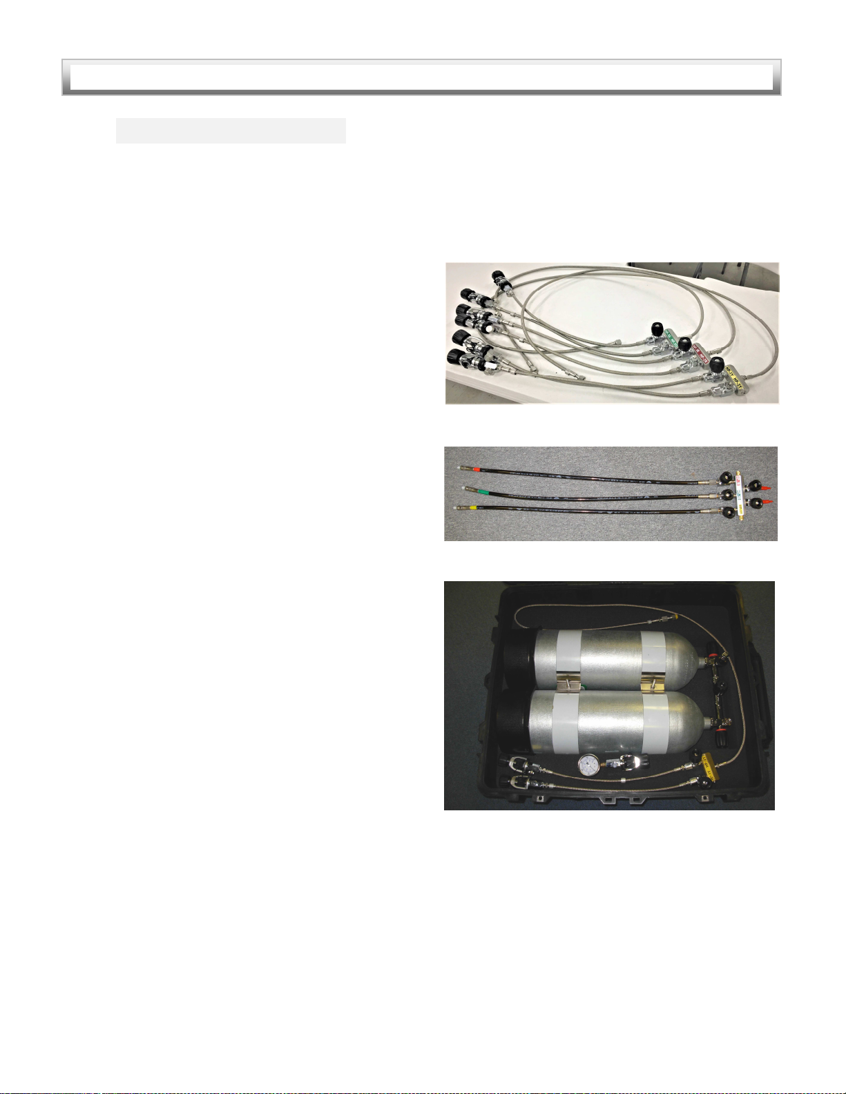
XLDS operates as an interme iate compensate
system. The XLDS system uses a specially
esigne 1/4" main gas umbilical assembly, that
re uces the weight an bulk of the umbilicals to
approximately half that of the lightest assemblies
normally use for surface supply iving. The
umbilicals are supplie air from the console, at
pressures between 350-375 PSIG (24-26 bar), to a
volume compensate pressure control system,
worn by the iver, known as the iver worn
interme iate manifol compensating regulator
system (ICS). The manifol is integrate with a 0.8
liter accumulator an manifol regulator system,
which re uces high velocity me ium pressure
breathing air (350 PSIG), from the umbilical, to
between 150-170 PSIG an supplies it to the
helmet or full face mask being use .
During inhalation, the ICS elivers breathing air to
the eman helmet or full-face mask with
minimal pressure rop, allowing for low
inhalation effort. During the exhalation cycle, the
system quickly buil s pressure for the next
inhalation cycle. Breathing performance of the
system allows breathing rates of up to 90 RMV to
epths of 100 FSW, an up to 75 RMV to epths
of 132 FSW, with most mo el KMDSI helmets an
ban masks, an at 75 RMV to 165 FSW when
using the KMDSI EXO- 26 BR. Both the positive
an non-positive pressure AGA
TM
FFM,
can be
use at work rates of 75 RMV, to epths of 150
FSW.
Conventional Surface Supplied
Diving
The surface air control consoles (RDC-2 an RDC-
3) can also be use as conventional air control
console, for eman mo e surface supplie
iving, with eman mo e Helmets an Masks.
When reference to conventional surface supplie
iving is given, it refers to the RDC-2 or RDC-3
console use with stan ar umbilicals an over
bottom tracking of supply pressures, no more
than 200-250 PSIG OB. When the RDC-2 or RDC-3
consoles are use for conventional air iving,
supply pressure can be regulate to each iver,
IAW the operational pressure an supply
requirements, ictate by the UBA being use ,
an IAW the recommen e performance
specifications as outline in this user gui e.
When using with conventional 3/8” umbilicals,
the RDC relief valves, shoul be reset to relieve
between 290-300 psig, verse the 390-400 psig
setting, when using with the XLDS system.
Currently the RDC-2 an RDC-3, are certifie by
Dive Lab, for use with all properly maintaine
current pro uction mo els of KMDSI Ban Masks,
Helmets, an Full Face Masks properly configure
for conventional surface supplie iving. Other
equipment may be use , contact Dive Lab for
a itional information.

© Copyright 2003-2019 Dive Lab® Inc. All rights reserve .
This Gui e is ma e available for the express use of owners an users of the Dive Lab XLDS systems.
This information is subject to perio ic up ates an changes. Always check the Dive Lab web site for the latest versions.
Document XLDS Gui e – Section Two
Revise July 17, 2019
4
SECTION TWO: CONCEPT AND INTENDED USE
XLDS Major Subsystems
Both the XLDS RDC-2 an RDC-3 share the same
basic subsystems an components lai out in a
similar fashion. These inclu e:
• High Pressure Supply System
• Rapi Deployment Control Console (RDC)
• 1/4” Ultra Light Umbilicals
• Interme iate Manifol Compensating
System (ICS)
• Emergency Gas System (EGS)
• Performance Certifie UBA Helmet / Full
Face Mask System
DANGER
All Divers using the XLDS an associate man
worn equipment, must be me ically fit. All
users must have a current iving me ical exam,
by a physician knowle geable in the
requirements of iving physicals.
WARNING
The Lightweight System must only be use with
properly maintaine an service Helmets,
Masks, Emergency Gas Systems, an support
equipment, as outline in this User Gui e.
DANGER
Only persons properly traine in the practice of
surface supplie iving an surface supplie
iving operations shoul use this equipment.
Failure to have proper training an experience
coul result in injury or eath.
DANGER
The XLDS-RDC-2, an XLDS-RDC-3 high-
pressure systems, shoul not be use with
pure oxygen, or oxygen enriche breathing
gases, with an oxygen percentage greater
than 21% by volume. Use of oxygen or
oxygen enriche breathing gases in the high-
pressure systems, may result in fire or
explosion, resulting in serious injury or eath.
DANGER
When the RDC-2 or RDC-3 is use as the XLDS,
the Consoles must be configure an
operate with the complete XLDS system only.
It must be use within the gui elines of the
operational specifications of the user gui e.
Only eman mo e Helmets an Mask
mo els, that have been Certifie by Dive Lab,
for use with the complete system shoul be
use . Failure to follow the instructions in the
Gui e may result in serious injury or eath.

© Copyright 2003-2019 Dive Lab® Inc. All rights reserve .
This Gui e is ma e available for the express use of owners an users of the Dive Lab XLDS systems.
This information is subject to perio ic up ates an changes. Always check the Dive Lab web site for the latest versions.
Document XLDS Gui e – Section Two
Revise July 17, 2019
5
SECTION TWO: CONCEPT AND INTENDED USE
High Pressure Supply
The High-Pressure Supply System is for air iving
only, an is not esigne or inten e for
breathing gases with an oxygen content greater
than 21% oxygen by volume however the system
has provisions for integration of pure oxygen or
oxygen enriche gas for in water ecompression,
using a separate Dive Lab system known as the
Surface Supply Oxygen Control Console System
(SSOCS). The SSOCS that can be interface with
the re uce pressure Manifol . The oxygen
system is inten e for use to a maximum epth
of 50 FSW, for ecompression purposes only.
The HP air supply system is rate for up to 5000
psig service with properly rate fittings. The HP
system shoul only be supplie with breathing
quality air via sources at supply pressures of 400
PSIG or greater capable of supplying at least 500
LPM. Typical air supply sources inclu e stan ar
single or ouble SCUBA Cylin ers, Fire Fighting
Cylin ers, an /or any high-pressure supply up to
4350 psig, if DIN fittings are in use.
The stan ar High-Pressure Air Supply System for
both the RDC-2 an RDC-3 for each iver circuit
consists of two SCUBA “A” Yokes / DIN
combination connections with Blee Valves, an
short (12”-18”) whips. Each set of Yokes sen s air
via the short Whips, to an isolation valve on a
small manifol block use for supply, isolation
an air switching. From the Junction Block air
travels via a 6’ to 25’ long whip, to the console
pressure regulators. On the RDC-3 the thir iver
(Yellow Diver), is the stan by.
Each HP supply assembly quickly connects to the
Regulator Inlets through the use of 72” long
whips, ZCO O-ring fittings. The “A” Yokes are
rate for 3500 psig an the DIN fittings, are rate
for 4350 PSIG service. Other configurations of
supply whips an fittings are available. The flow
capability of the high-pressure system, enables
stan ar SCUBA Cylin ers, to be use as low as
380 PSIG, before Cylin er switch-out is necessary.
Other supply whips an configurations, can be
use , provi ing they can provi e the proper
volume.
Typical High Pressure Assemblies
Special Purpose High Pressure Assembly
High Pressure Assembly with Gas Storage Cylin ers

© Copyright 2003-2019 Dive Lab® Inc. All rights reserve .
This Gui e is ma e available for the express use of owners an users of the Dive Lab XLDS systems.
This information is subject to perio ic up ates an changes. Always check the Dive Lab web site for the latest versions.
Document XLDS Gui e – Section Three
Revise July 17, 2019
6
S
ECTION THREE: CONFIGURATION AND USE
Rapid Deployment Air Control
Console
The breathing gas control console regulates an
controls the ivers breathing air as well as
pneumofathometer air for epth sensing. Both
the two an three iver console (RDC-2, RDC-3),
have one complete circuit for each iver lai out
in a simple fashion, an the components use in
each console, are the same. The Supply to each
iver’s circuit, starts with a VCO O-ring fitting, or
# 4 37° JIC fitting, attache to a stainless steel
Street “T”, connecte to each ivers pressure
regulator. The regulator is rate for a maximum
inlet supply pressure of 5000 PSIG, an a
maximum outlet pressure of 400 PSIG. Re uce
air pressure passes through a one-way valve,
allowing air to only travel into the Manifol . Each
manifol assembly contains a 0-600 PSIG,
re uce pressure gauge, Pneumofathometer
supply valve, relief valve (set to relieve between
390-400 psig), an iver supply valve. Each
manifol has a 1/2" NPT, 1/2"-20, an 3/8”-28
straight threa gauge calibration port, an a main
supply cross connect, which allows interme iate
air from either circuit, to be line up to the other
ivers re uce pressure circuit(s). Each iver’s
low-pressure (ALP) supply valves, are quick acting
quarter turn valves. The manifol is the
foun ation, that hol s all gas train components,
an secures to a 1/2” thick high ensity
polyethylene plastic foun ation plate, that is
through bolte to the console box, making the
piping system secure.
The pneumofathometer gauges on the 2 an 3
Diver Console, are mounte in the console li ,
along with or without an installe iver intercom
(Optional). The 3 Diver Console can be equippe
with several ifferent iver intercom units
(optional), but oes not have a iver intercom
integrate into box. Both 2 an 3 RDC’s are
normally equippe with in ex locking quick
connect fittings, for attaching the
pneumofathometer an breathing air supply
Umbilicals.
XLDS System Restrictions
The XLDS with 1/4" umbilicals an iver worn
manifol compensating system, has a normal
umbilical restriction, to a maximum length of 330’
(100 meters). Special custom hoses can be
manufacture on a case by case basis, with
certain epths limitations.
When RDC-2 or 3 is use as a stan ar control
console with 3/8” umbilicals, umbilical length
shoul be restricte to 600’ (200 meters) or less,
an a maximum iving epth of 220 fsw. The
system must only be operate an use within
the gui elines of this user gui e, an the
operation specifications escribe in this gui e.
XLDS RDC-3 XLDS RDC-2

© Copyright 2003-2019 Dive Lab® Inc. All rights reserve .
This Gui e is ma e available for the express use of owners an users of the Dive Lab XLDS systems.
This information is subject to perio ic up ates an changes. Always check the Dive Lab web site for the latest versions.
Document XLDS Gui e – Section Three
Revise July 17, 2019
7
S
ECTION THREE: CONFIGURATION AND USE
Ultra Light Umbilicals
The XLDS umbilicals have been specially esigne
for use with the manifol compensating system,
an RDC-2 or RDC-3, an are not inten e to be
use for conventional surface supplie iving.
The umbilical assembly is comprise of four major
components, that are twiste together to form
the complete umbilical assembly, breathing gas
hose, communications /strength member,
penumofathometer hose, an 20’ grab line. The
ivers en has a “D” ring with snap shackle, that
is attache to the communication/strength, an
grab line for securing to the iver worn harness.
The 1/4" I.D. supply umbilical has a esign
pressure of 1500 psig, an is rate for a normal
maximum system working pressure of 400 psig.
Both en s have SS swage 1/4" MPT fittings,
which connect to a 6” a apter hose, that has 1/4”
FNPT on one en , an 9/16 O
2
strait threa on
the other. The topsi e en connects to a 9/16” O
2
fitting on the outlet of each ivers control valve
ALP1R, ALP2G, ALP-3Y on the RDC. At the ivers
en , the umbilical to ICS interface hose attaches
to a 9/16” CGA O
2,
male fitting on the ICS one
way valve.
Pneumo hook-up
Stan ar XLDS Umbilical 300 ft.
Communication Strength
Member
The communication / strength member contains
four (4) wires, for communications an a
polyester strength member. The assembly is
encase in a polyurethane jacket. The strength
member has a safe lifting capacity of 800 lbs, an
a minimum breaking strain of 2200 lbs.
Pneumofathometer Hose
The Pneumofathometer Hose is ma e from black
nylon plastic, 3/16” I.D. rate , for a maximum
internal pressure of 200 PSIG.
Grab Line
The Grab Line is twiste into with the first 20 feet
of Umbilical at the ivers en , to allow for easier
han ling by the ten ers, an to ai in lifting if
necessary. The Line is stan ar 3/8” or 1/2"
brai e nylon.
Diver Worn Harness and
Manifold Compensating
System
The iver worn interme iate compensating
system (ICS), was esigne to allow 1/4" I.D. air
supply umbilicals, to be use with stan ar
eman mo e helmets an masks. The system
allows ivers the ability to ive to epths,
previously only attainable when using heavy 3/8”
Umbilicals, an large support systems. The ICS
system with accumulator cylin er attaches to the
right si e of the mo ifie Atlantic Diving
Equipment, or Miller Bell Harness, an fits
securely behin the right arm, in a specially fitte
holster. The umbilical attaches to the ICS, which
re uces the normal umbilical supply of 350 psig,
to between 150-170 psig, over ambient pressure
to the eman mo e helmet or mask being use .

© Copyright 2003-2019 Dive Lab® Inc. All rights reserve .
This Gui e is ma e available for the express use of owners an users of the Dive Lab XLDS systems.
This information is subject to perio ic up ates an changes. Always check the Dive Lab web site for the latest versions.
Document XLDS Gui e – Section Three
Revise July 17, 2019
8
S
ECTION THREE: CONFIGURATION AND USE
Because the manifol volume tank receives
me ium pressure high velocity air from the
umbilical, the system is capable of provi ing the
necessary peak flows, require to attain
respiratory work rates (RMV), as high as 75 RMV,
with specifie helmets an masks to epths of
190 FSW.
ICS/EGS Manifol Compensating System with 6 cu. Ft. surge
bottle
Harness Assembly an ICS Assembly
XLDS-RDC-3 Specifications
•Box Weight 87 lbs.
• Outer Dimensions Length 28 inches
• Wi th 27 inches
• Height 15 inches
• Number Diver Circuits 3, Re , Green, Yellow
• Max Depth: Using 1/4” I.D. Umbilical one
continuous length up to 330’ long, 165 fsw
• Maximum High Pressure Supply 3000-5000
psig
• Minimum Console Supply Pressure
375 psig
• Maximum Low Pressure Outlet Pressure:
375- 400 psig
• Low Pressure Relief Setting: 400-420 psig
• High Pressure Gauges: 3, 0-5000 psig
• Low pressure Gauges: 3, 0-600 psig
• Pneumofathometer Gauges: 3, 0-250 fsw
Surface Supply Console Flow
Capability with 300 foot long
1/4” umbilicals and ICS
•Minimum Flow: with 800 psig HP supply an
Re ucer, set static to 350 psig 700 slpm (scfm).
• Minimum Flow: 400 psig HP supply, re ucer
set static to 350 psig, 550 slpm (scfm).
Work of Breathing Performance
Work of breathing performance ata is base on
one iver, breathing from a HP supply of 400 psig,
with the SCC regulator, set static at 350 psig. The
I.P. of the ICS set between 150-170 PSIG.
Umbilical length, 300’, maximum epth 132 fsw.

© Copyright 2003-2019 Dive Lab® Inc. All rights reserve .
This Gui e is ma e available for the express use of owners an users of the Dive Lab XLDS systems.
This information is subject to perio ic up ates an changes. Always check the Dive Lab web site for the latest versions.
Document XLDS Gui e – Section Three
Revise July 17, 2019
9
S
ECTION THREE: CONFIGURATION AND USE
High Pressure Air System
The stan ar high-pressure air attachment to
SCUBA cylin ers, are either DIN or SCUBA “A”
Yokes, rate for a maximum supply pressure of
(4350 psig DIN), (3500 psig A-Yoke). All stan ar
RDC-2 an RDC-3 Whips, are rate for a
maximum working pressure of 5000 psig, or as
marke on the Whip. Other Whips up to 25 feet
in length, can be use , provi ing they have a
minimum I.D. of 0.112. Whips over 25 feet in
length, shoul have a minimum I.D. of 0.160.
DIN Yoke Assembly
Proper rate DIN fittings, as well as CGA fittings,
can be use to their appropriate working
pressure, up to the systems maximum supply
pressure of 5000 psig.
Each ivers’ circuit comes stan ar , with two
cylin er attachment whips an yokes, which
attach to a routing block an shut-off valves.
Each supply system allows attachment, to two
single SCUBA cylin ers, or two sets of twin SCUBA
cylin ers, if twin cylin ers are being use . Each
ivers’ circuit, shoul always be set-up with each
yoke attache to a fully charge cylin er, an
only one cylin er supply shoul be on line at a
time, so that when the gas supply reaches
approximately 400 psig, it can be secure an the
other supply opene .
By keeping the system set-up in this manner, the
eplete cylin er(s) can then be change out,
an a full cylin er place in the rea y, without
interruption of breathing air. Prior to attaching
the cylin ers, each HP circuit shoul be
inspecte , for signs of amage.
HP Whip Assembly - 3 Diver
Diver Intermediate
Compensating Manifold Gas
Flow
The ivers’ umbilical snap shackle attaches to D
ring on the left si e of the harness. The Umbilical
connects to the male CGA O2 fitting, on the
compensating manifol one way valve. The one
way valve allows the umbilical gas to supply the
manifol regulator an accumulator. The
manifol regulator re uces the umbilical supply
to a normal supply pressure, between 150-170
psig over ambient. Air then travels up a 5/16”
interme iate whip, to the helmet or mask being
use . The manifol is also equippe with a multi-
turn EGS Valve, for interface with the emergency
air system.
WARNING
The HP whips supplie are rate for 5000 psig
service, but shoul not be use at pressures
greater than 3500 psig, unless the Yokes are
replace with supply fittings, rate for the
increase pressure (DIN).
CAUTION
Ensure the Cylin er Valve Outlet opening is
pointing away, in a safe irection, then slightly
crack open an shut each Cylin er Valve
momentarily, to ispel any ust or irt,that may be
present in the Valve Orifice.

© Copyright 2003-2019 Dive Lab® Inc. All rights reserve .
This Gui e is ma e available for the express use of owners an users of the Dive Lab XLDS systems.
This information is subject to perio ic up ates an changes. Always check the Dive Lab web site for the latest versions.
Document XLDS Gui e – Section Three
Revise July 17, 2019
10
S
ECTION THREE: CONFIGURATION AND USE
Emergency Gas System
The emergency gas system is attache to the
mo ifie harness. The emergency gas system is
ma e up of a goo quality first stage SCUBA
regulator, an high-pressure cylin er. Cylin er
capacity must be selecte base on the epth,
an potential hazar s that may be encountere .
It is strongly recommen e that the cylin er
capacity be sufficient, to allow a normal ascent to
the surface, or to a place of safety where
breathing gas can be restore . The regulator use
with the cylin er, shoul be equippe with a
relief / blee valve. The blee valve allows excess
pressure to vent from the EGS supply whip, in the
event the first stage evelops a minor leak.
Without the blee valve, a minor first stage leak,
coul cause the pressure within the EGS to rise,
above the maximum safe working pressure of the
LP supply whip causing the whip to rupture,
resulting in loss of the EGS system. The XLDS
comes stan ar with either a 30 or 40 C.F.
emergency cylin er which fits the stan ar
system cylin er straps. If larger iameter
cylin ers are to be use the longer cylin er
retaining straps will be require .
EGS Assembly an ICS Manifol Compensating System
WARNING
Un er no circumstance shoul the XLDS iving
system EVER be use without a fully functioning
man worn emergency gas system.

© Copyright 2003-2019 Dive Lab® Inc. All rights reserve .
This Gui e is ma e available for the express use of owners an users of the Dive Lab XLDS systems.
This information is subject to perio ic up ates an changes. Always check the Dive Lab web site for the latest versions.
Document XLDS Gui e – Section Four A
Revise September 30, 2019
11
SECTION FOUR
A
: RDC REPAIR / MAINTENANCE /
OVERHAUL
General Cleaning / Inspection
Procedures
Prior to commencement of system work, a clean
area shoul be establishe an tools to be use
must be clean an free of grease an oil. Persons
performing repairs an overhauls shoul be
traine an experience .
Cleaning Solution
All components of the XLDS an RDC shoul be
cleane using a etergent like Simple Green
ilute , with clean filtere water at a ratio of 1
an 1/2 ounces of etergent to each gallon of
water. Regular han washing type ish etergent,
or Non-Ionic Detergent may also be use by
mixing at a ratio of, one tea spoon per gallon of
water. All components must be thoroughly rinse
with con ition fresh water filtere to 5 micron or
less. After rinsing, take a sample of the final rinse
water in a clear container an perform a shake
test to check for su s, re-rinse components if
su s are observe uring shake test.
Corrosion
Parts showing corrosion shoul be cleane with
etergent an water to remove as much ol
lubricant as possible, an then aci cleane by
immersion in a 50/50 solution of white vinegar
an water for up to 4 hrs. Re-clean parts using
the etergent solution an rinse thoroughly.
Inspection
After cleaning, the parts shoul be inspecte for
obvious contamination an re-cleane as
necessary an carefully inspecte for signs of
wear an amage.
Drying
All parts shoul be left to air ry in a clean
controlle space, or rie using nitrogen or
ivers’ air. A hair ryer set on a low heat is also an
effective way of rying parts. When parts are ry,
inspect using a bright light. Complete a final visual
inspection an if any contamination is foun , the
components must be re-cleane .
Control of Cleane Components
All parts cleane shoul be protecte by seale
airtight esignate containers or in ivi ually
bagge as necessary until reinstalle in the
system. All attempts shoul be ma e to maintain
Foreign Material Exclusion (FME) of all parts an
components, uring all phases of the
repair/overhaul process.
Cleaning an Han ling of O-rings
All O-rings use in the XLDS an RDC will be
cleane using a etergent solution then
thoroughly rinse , rie an seale , in an
appropriate container. Once cleane , all O-rings
shoul only be han le while wearing gloves. O-
rings shoul not be lubricate , until they are
stage , an rea y to be installe into the
components.
Lubrication
Lubricant applie to O-rings an components,
must be one sparingly. The recommen e
lubricant is Christo-Lube.
Pipe Threads
Pipe threa fittings in high- an low-pressure
breathing gas systems, are often use as an
alternative to straight threa O-ring or wel e
fittings ue to cost, complexity, an selection.
Pipe threa fittings offer an attractive alternative
to large ben ra ius wel e , or compression joint
systems, an can pro uce exceptionally strong,
reliable, compact systems.
However, shock an vibration especially in
portable systems can cause movement between
joints resulting in leaks. Unlike O-Ring fittings,

© Copyright 2003-2019 Dive Lab® Inc. All rights reserve .
This Gui e is ma e available for the express use of owners an users of the Dive Lab XLDS systems.
This information is subject to perio ic up ates an changes. Always check the Dive Lab web site for the latest versions.
Document XLDS Gui e – Section Four A
Revise September 30, 2019
12
SECTION FOUR
A
: RDC REPAIR / MAINTENANCE /
OVERHAUL
minor pipe threa fitting leaks will not su enly
or rastically increase because of the natural
locking nature of pipe threa s. Teflon tape is use
both as a lubricant an a sealant. As a lubricant,
the tape keeps the threa s from galling. As a
sealant the tape pro uces a gas tight seal. Unlike
pipe fittings, minor Leaks in O-Ring fittings cannot
be tolerate , because the seal is ma e by the O-
Ring only, between two surfaces an leakage will
normally increase rapi ly especially if there is any
movement of the fittings. In some cases, parts of
the O-Ring may extru e causing su en massive
leakage or total failure of the O-ring seal.
Unlike O-rings, the pipe threa s use sealing tape
which will usually show up as a minor leak an
will not progress significantly as long as there is
no movement of the fitting. Very minor leakage
in pipe threa fittings is common, shoul be
expecte , an oes not pose an operational
hazar in “AIR SYSTEMS”, or a significant
re uction in operational capability as long as the
leaks are minor, can be i entifie an quantifie .
All leaks shoul be repaire as soon as possible /
practical. It shoul be un erstoo , that in
portable fast response systems like the XLDS
which can be subjecte to shock an vibration
uring transport minor leaks may result that may
have to wait before repairs can be ma e.
The only way to reme y leaks in pipe threa
fittings, is to epressurize the system,
isassemble the joint, remove ol sealing tape,
brush clean an inspect the threa s for amage,
an then re-tape an re-make the joint. Because
this is often impractical to accomplish in the fiel ,
minor leakage uring system use, can be an
acceptable alternative to fiel repairs in or er to
safely continue with iving operations until re-
sealing can be accomplishe .
Checking and Quantifying
Leaks
There is a full system step by step test proce ure
for pressure testing. XLDS RDC Console Annual
Pressure /joint Tightness Testing Test which
shoul be one annually, but can also be one at
any time leakage is suspecte . However, as a
quick fiel check if necessary, complete a check
as escribe herein to quantify leakage.
Checking for Leaks Quick Check: To check for
leaks, ensure the umbilical supply valves,
pneumofathometer valves, an cross connect
valves are shut, then slowly open each cylin er
HP supply valve, an each supply block valve
approximately 1/4 -1/2 turn, an pressurize each
HP circuit, using at least a 3000 PSIG supply
pressure. Loa each regulator to 350-400 PSIG
an allow the system to settle for at least one
minute then secure the cylin er valves only, an
recor the high an low pressures an the time.
Allow the system to sit for ten minutes, then
check the gauges. If there has been any loss of
pressure, apply soapy water solution to all joints
an fittings to i entify the leaks. Very minor leaks
at pipe threa e joints, that cause a rop of
gauge pressure of no more than 10 PSIG in ten
minutes, with the supply isolate at the HP blocks
as note on each of the high-pressure gauges, o
not require imme iate re-sealing. Pressure loss in
excess of 10 PSIG, represents a gas loss in excess
of 3 liters in ten minutes, an shoul be correcte
before the system is use . This leakage is
acceptable for pipe threa fittings an joints only,
WARNING
Never tighten fittings or components while the
system is pressurize . Attempting to tighten
fittings, while the system is pressurize , coul
result in component failure, resulting in
serious injury or eath.

© Copyright 2003-2019 Dive Lab® Inc. All rights reserve .
This Gui e is ma e available for the express use of owners an users of the Dive Lab XLDS systems.
This information is subject to perio ic up ates an changes. Always check the Dive Lab web site for the latest versions.
Document XLDS Gui e – Section Four A
Revise September 30, 2019
13
SECTION FOUR
A
: RDC REPAIR / MAINTENANCE /
OVERHAUL
O-ring an or any other types of leakage must be
repaire prior to use. Use the Dive Lab Appen ix
A2.1A Pressure/Joint Tightness proce ure.
Teflon Tape
When making up pipe fittings of 1/4" or smaller,
for best results, use three (3) mil thickness
Teflon® tape. The tape use shoul be 1/4" wi e.
Half inch (1/2”) wi e, three (3) mil tape on 1/4"
or smaller pipe threa s, can be use but will not
stretch an form to the small iameter threa s,
as well as 1/4" tape. Normally, 1-1/2 wraps
applie un er tension, is all that is require on
brass to brass fittings, however for stainless
fittings we recommen up to two an a half (2-
1/2) wraps to achieve a tight seal. The tape
shoul be applie un er tension, starting 1-1/2 to
2 threa s back, from the start of the fitting. In
a ition, we recommen applying a small
amount of Christ Lube over the Teflon® tape.
Making up 3/8” to 1/2” Pipe Fittings
When making up three eighths (3/8”), or half inch
(1/2") pipe fittings, three (3) mil thickness Teflon
tape, or six (6) mil thickness tape, half inch (1/2")
wi e may be use . If three (3) mil is use , use two
(3) to four (4) wraps. If six (6) mil is use , use one
an a half (1-1/2) to two (2) wraps. Apply tape
un er tension starting one an a half (1-½) to two
(2) threa s back from the start of the threa s.
Torque/Tightening
Pipe threa s shoul be tightene using goo
engineering practice. Tighten pipe threa s
securely, but o not over tighten. Normally pipe
threa s shoul engage at least 1 ½ to 2 full turns
by han , followe by at least 2 full turns by
wrench.
RDC Regulator
The stan ar regulators use for the RDC, are
Aqua Environments® mo el 873 piston type han
loa e regulator of a balance poppet, esigne
for high flow with a minimum effect on outlet
pressure. The poppet assembly is containe in a
cartri ge, with internal filtration for easy in-fiel
changing. The regulator is NOT inten e for
oxygen, or oxygen enriche gas mixtures. The
regulator shoul be use with filtere breathing
quality air only.
Specifications
· Maximum inlet pressure 5000 PSIG (340 BAR)
· Outlet pressure 0 - 400 PSIG
· Flow coefficient (Cv) 0.8
(equivalent to 0.23” orifice)
· Rise of outlet pressure with rop of inlet
pressure 10 PSIG/1000 PSIG
· Materials – bo y an cap – aluminum
· Internals – brass, stainless
· Seals – KEL-F, Buna, Viton
· Fittings – ¼” FNPT inlet
½” FNPT outlet
· Size – 3” ia. x 6” long
Installation
Use only Teflon tape on inlet an outlet threa s
of the aluminum regulators never use lubricant
on aluminum threa s use in high pressure piping
systems. Avoi over tightening of pipe threa s.
Pipe threa fittings shoul threa in
approximately 1 ½ to 2 threa s by han , an 2
threa s by wrench. Normal torque, applie with
an 8-12 inch long wrench, is ample.
The inlet (HP) is on the left, when facing the
a justing knob with the two gauge ports upwar .
NOTICE
The purpose for the allowable leakage,
is to allow
continue use of the system to be use , until
repairs can be ma e.

© Copyright 2003-2019 Dive Lab® Inc. All rights reserve .
This Gui e is ma e available for the express use of owners an users of the Dive Lab XLDS systems.
This information is subject to perio ic up ates an changes. Always check the Dive Lab web site for the latest versions.
Document XLDS Gui e – Section Four A
Revise September 30, 2019
14
SECTION FOUR
A
: RDC REPAIR / MAINTENANCE /
OVERHAUL
The ½” port is the outlet. The ¼” port a jacent to
the ½” port, is the LP that is plugge with a pipe
plug. The port to the left is a HP outlet port an is
also plugge .
The HP inlet port is irectly on the opposite si e
of the regulator bo y, opposite the large ½” port.
Operation
Outlet pressure is a juste by rotating the
regulator han wheel, to the esire value, as
rea on the outlet gauge. When re ucing the
pressure, the regulator will not vent the LP
manifol , because of the check valve at the outlet
of the regulator. It will vent slightly, when first
backe off via the vent hole near the cap. This is
normal. To lower the manifol pressure, vent the
umbilical pressure to below the new setting, then
increase pressure to the new setting.
Figure 1
Trouble Shooting
The number one cause of leakage in the high-
pressure regulator, is a irty corro e HP seat,
ue to irt or moisture in the air supply. If
leakage occurs through the regulator, or out the
regulator vent, allow the inlet an outlet
pressure, to equalize by shutting off the inlet. If
leakage continues after the inlet an outlet
equalize, the vent seat (8) or piston seal (6) is
leaking. Replace both. If leakage stops, when the
inlet an outlet pressure equalize, the poppet
cartri ge item (2) is leaking. Replace. Consult Dive
Lab, if necessary.
CAUTION
An outlet gauge an relief valve set no higher
than 400 psig,
shoul be connecte to LP
manifol .
CAUTION
Maintenance an Repair
As with any regula
tor or valve, particulates or
moisture,
can plug or freeze the internal filter or
valve seat. This can occur,
when air compressor
supply ryers are not a equate,
or are not use
regularly. The regulator shoul be overhaule ,
at
least every three years. Sy
stems in continuous
use,
may require overhaul more often. The user
shoul establish time intervals for changing the
valve cartri ge, filter, an any upstream ryers
,
base on experience an service con itions.
Back-up systems shoul be use in very criti
cal
applications,
since fiel maintenance is har to
ensure. The poppet cartri ge (2) i
s a factory
assemble item,
an shoul be replace as an
assembly. Always keep at least one spare
cartri ge on han for repairs. In all cases,
the
unit can be returne
to Dive Lab for repair.
Maintenance or repairs,
shoul only be one by
qualifie personnel,
allowing the rawings an
parts lists herein.
NOTICE
Overhaul of the regulator shoul be limite to
cleaning an changing the HP cartri ge assembly
as well as the upper piston assembly.

© Copyright 2003-2019 Dive Lab® Inc. All rights reserve .
This Gui e is ma e available for the express use of owners an users of the Dive Lab XLDS systems.
This information is subject to perio ic up ates an changes. Always check the Dive Lab web site for the latest versions.
Document XLDS Gui e – Section Four A
Revise September 30, 2019
15
SECTION FOUR
A
: RDC REPAIR / MAINTENANCE /
OVERHAUL
Regulator Overhaul
1. Do not use silicone or Christo Lube, on
threa e high, or low-pressure inlet outlet
fittings. Use Christo Lube MCG 121 on O-
rings, on the bearing (13) an (12), an on
threa s between items (16) an (17), an
between (1) an (18).
2. The regulator internal components, can be
overhaule , with the bottom en of the
regulator in place. The regulator bottom, nee
not, be remove from the system.
3. Remove the regulator a justment knob (15)
an stem (16), as an assembly.
Figure 2
4. Apply several wraps of electrician’s tape or
equivalent, aroun the upper housing (18) to
prevent scratching, then using a “clean
e icate ” oil filter wrench, to loosen the
upper bo y (18), then remove by han .
Figure 3
Figure 4
5. Remove items (14), (12), (13), (10), (11), as a
stack, place these items in a small, clean
container.
Figure 5
6. Carefully remove the piston housing, clean
an inspect all components. Lightly lubricate
new O-rings on new service kit. Figure 6.
NOTICE
The above items are outsi e of the breathing
air system. If the items show no signs of irt
an corrosion, cleaning is not require . If in
oubt, clean an re-lubricate with Christo lube,
or foo gra e Silicone grease.
NOTICE
Aqua Environments regulators ma e after 2015
have a small hole on each si e of the regulator
bo y,
to allow for using a spanner wrench
instea of an oil filter wrench.

© Copyright 2003-2019 Dive Lab® Inc. All rights reserve .
This Gui e is ma e available for the express use of owners an users of the Dive Lab XLDS systems.
This information is subject to perio ic up ates an changes. Always check the Dive Lab web site for the latest versions.
Document XLDS Gui e – Section Four A
Revise September 30, 2019
16
SECTION FOUR
A
: RDC REPAIR / MAINTENANCE /
OVERHAUL
Figure 6
7. Remove low pressure piston assembly.
Figure 7
8. Remove high pressure valve assembly, in
regulator bo y.
Figure 8
9. Inspect regulator bo y for amage an /or
corrosion. If nothing foun install new kit.
10. Install NEW high pressure valve assembly, in
regulator bo y. Tighten to 80-100 inch lbs.
Figure 9
11. Install NEW low pressure piston assembly.
Figure 10
Figure 11
4. Lay the stop ring (9) own on top of the lower
regulator bo y (1) as shown so the bevel is
own, see Figure 13 & 14. Carefully place the
piston housing assembly over the bevel ring
into place. Use care not to rop the seat.
NOTICE
Packing the vent seat area with Christo Lube, is
one to secure the seat uring assembly.
NOTICE
If the housing is heavily corro e , remove it in
accor ance with the proce ures, liste in the
one-way valve removal section.
This manual suits for next models
1
Table of contents