DOCtron Instant Mastering Chain v 5.1.7 Installation manual

Martin Stimming's
Instant Mastering Chain
v 5.1.7
Set-up and operating instructions
Introduction 2
Safety 3
Overview 4
Circuit Parts In Detail 5
Tec Specs 14
IMC5 1 © DOCtron 2021

Introduction
IntroductionIntroduction
Introduction
IMC, meanwhile in version 5, is an idea and commissioned work of one of Germany’s most credible
techno artists: Martin Stimming. he original idea behind IMC is to create a device that is small, light
and handy, allowing a liveshow to sound loud and thick without a computer on stage. While being tied
to the studio in 2020 and 2021 Stimming found out how useful it is there as well.
he signal path is consistently analog. In the course of development, the operation was then digitized and
the circuit itself continuously expanded and supplemented, based on Martin Stimming's experience with
the prototype devices in tough live use around the world.
From working together on this device, a friendship arose that spurred each other on to make IMC
accessible to everyone.
he result is a device that represents a milestone in technical and practical terms. IMC is elaborately
crafted by hand. he "inner values" are excellent and the case (also manufactured by DOCtron) made of
carbon underlines the maxim that allows a device in the smallest space, as easy and uncomplicated as
possible! An audio processor chain, which otherwise only digitally or with much higher budget and
physical space use would be possible.
IMC5 is a sound-shaping device used as a replacement for a classic mastering chain.
Included here is a British-style low and high-shelf EQ with dedicated bypass and a VCA based bus
compressor with FF/FB detector path.
he following instructions will now introduce the device in detail. he manual also represents the current
state of development.
In this tutorial we're scratching the surface. In the depth you have to go yourself ...
And now have fun with IMC !
Wassertrüdingen, June 2021
Mic ael „Doc“ Sc neider,
Doctron
IMC5 2 © DOCtron 2021

Safety
The blue exclamation mark is an indication to the user about safety-relevant
facts and facts relevant to service in this manual.
T e listed safety regulations s ould be carefully observed. Please observe t e following
instructions and read t is manual. For furt er questions please feel free to contact us.
We reserve t e rig t to make c anges to t e design or specifications.
We reserve t e rig t to make c anges to t e design or specifications.We reserve t e rig t to make c anges to t e design or specifications.
We reserve t e rig t to make c anges to t e design or specifications. If you need elp, if you ave questions or if you ave
a defect on t e device, please contact us. We're ere to elp.
IMC5 3 © DOCtron 2021
1. Always use a properly grounded power cord for this product.
Please never remove the ground of the power plug. This connection ensures safe and quiet operation and
is absolutely necessary for operation.
2. When installing into a rack, be sure to provide adequate ventilation.
The top and bottom ventilation slots are not decoration and should never be covered during operation. The
main reason for technical defects are mostly heat problems. In non-ventilated cabinets, use ventilation
panels (1H) between units (even if they don't look very beautiful) to prevent heat build-up.
3. Avoid places with strong magnetic fields.
The housings of the device are designed to protect the sensitive electronics from EMI and RFI. For rack
mounting, be sure to place devices with large power supplies or power amplifiers as far away from the unit
as possible in the rack. A separate routing of signal and power lines can also help to suppress EMI and
RFI as much as possible.
4. Protect your device from moisture and water splashes.
If water has entered the housing, disconnect it immediately from the mains and send it to us for inspection
to prevent major damage.
5. If you feel unsure about having to open the device to make settings, check fuses or set /
remove jumpers, please contact our support team. We're here to help.
6. Before you open the device to change jumpers or make adjustments, be sure to unplug
the power adapter before opening the case. Disconnect the device from the mains! Make
sure that no foreign parts remain in the device after completion of the work.

Overview
Here is t e entire circuit as a block diagram:
IMC5 4 © DOCtron 2021
Figure 1: block diagram

T e individual parts of t e circuit will be described later in detail.
T e general circuit description is initially limited to t e Audiopat .
Since bot c annels are identical, only t e left c annel is described ere, as s own in t e block
diagram.
IMC5 as a so-called "true-bypass", w ic means t at t e audio signal in t e de-energized state is
passed uninfluenced from input to output.
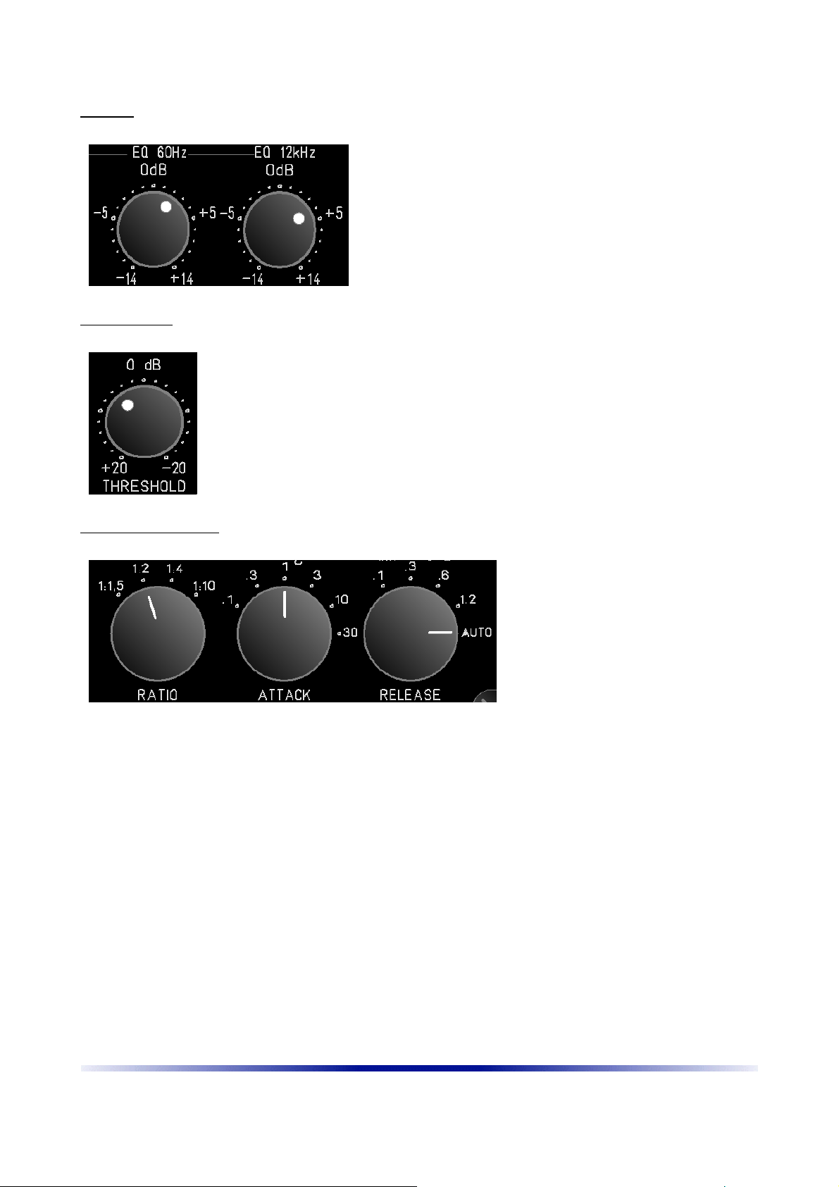
T e audio signal goes via an isolated 6,3mm jack socket to t e treble and bass EQ. T en t e audio
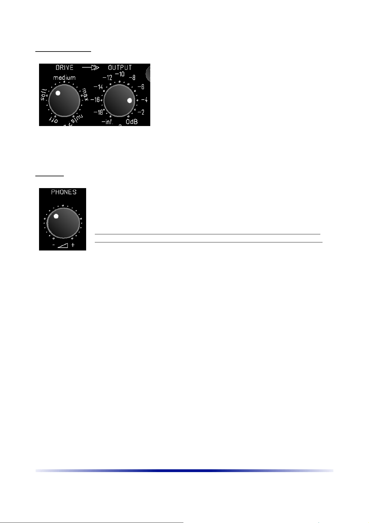
signal reac es a sound-forming, discrete operational amplifier (ORANGE DD). Now t e signal
reac es t e VCA compressor. T e output stage of t e compressor reac es a furt er amplifier stage,
w ic later determines t e saturation for t e output transformer. T e signal conditioned in t is way
now reac es a balancing driver stage and finally t e LUNDAHL output transformer.
At t e output of t e transformer, t e signal is routed to t e adjustable Output-Stage and to t e
eadp one amplifier.
T e remaining circuit parts work exclusively wit control voltage and are not in t e audio pat . T us,
no interference can enter t e signal pat . T e separation between audio pat and control voltages is
also made by using 6-way multilayer boards wit t eir own ground layers.
T is reduces interference enormously.
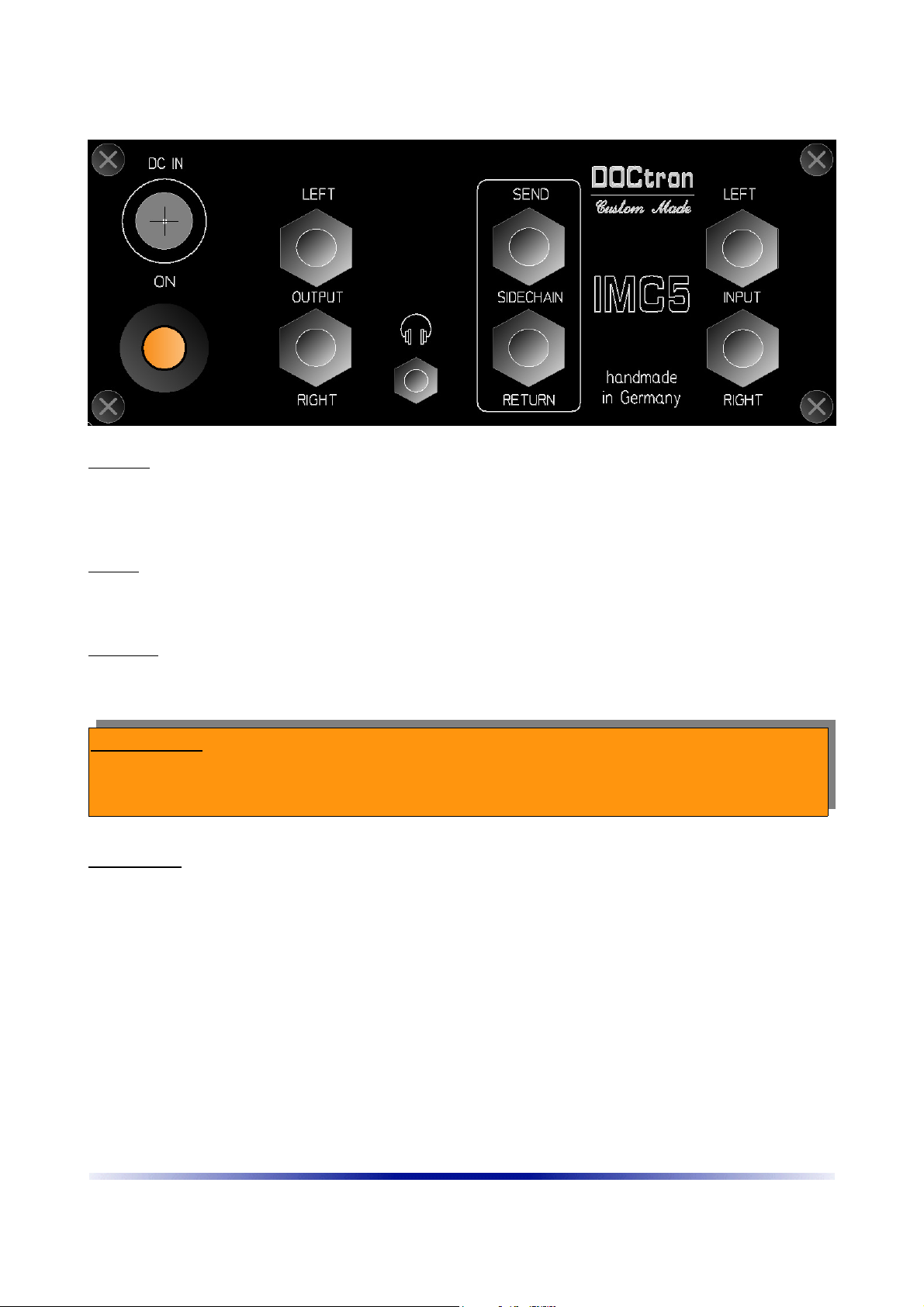
New in v5 is also an external Sidec ain (Send / Return on t e backplane).
T e power supply is via an external switc ing power supply. T is power supply must deliver at least
20V-24V. T e distribution of t e positive and negative supply voltages is carried out in t e device by
its own sub-switc ing power supplies.
Due to t e conductivity of t e carbon casing material, sufficient protection against t e outside world
is ensured. T e interior of t e ousing no longer needs to be sprayed wit conductive ink, as wit
IMC1.
The individual circuit parts in detail
The power supply:
The power supply:The power supply:
The power supply:
T e external switc ing power supply is plugged in wit a ollow plug on t e back of IMC5.
T e power supply as a very large voltage and frequency range and s ould be universally
applicable. Please c eck before connecting t e mains connection, if t e primary connection
corresponds to t e specifications on site! T e power plug s ould be unplugged w en connecting or
T e power plug s ould be unplugged w en connecting or T e power plug s ould be unplugged w en connecting or
T e power plug s ould be unplugged w en connecting or
disconnecting t e power supply to t e IMC.
disconnecting t e power supply to t e IMC.disconnecting t e power supply to t e IMC.
disconnecting t e power supply to t e IMC.
T e internal overload fuses could trigger. If t is is t e case, please wait a few minutes. T e fuses are
self-resetting. IMC5 as compre ensive reverse polarity protection and protection circuits against
“p antom-power”. All safety devices are self-resetting. An opening of t e ousing is t erefore not
necessary.
In general, all audio connections s ould be made before power is supplied to t e device. In addition
to t e main connector is a main switc . T is switc turns t e IMC5 on or off.
Here are t e tec nical data of t e external power supply used:
IMC5 5 © DOCtron 2021

Features and functions of t e series
Features and functions of t e seriesFeatures and functions of t e series
Features and functions of t e series
Table Switc ing Power Supply
Closed / Splas proof
Low standby consumption
Compact construction
Overload and s ort circuit proof
EU CoC V5 Tier 2 / EnergyStar DOE VI
Power Supply Specifications:
Power Supply Specifications:Power Supply Specifications:
Power Supply Specifications:
Input voltage: 90 - 264 V AC / 47 - 63 Hz
Power: 60W
Efficiency: DOE VI
Idle input: <0.15 W
Isolation: 3000 V AC / 1 min
Overcurrent protection: s ort-circuit protection
Overvoltage protection: 120%
Output: 24 V DC / 0 - 2.5 A
Ripple: 350 mVpp
Weig t: 320g
Input and output sockets:
Input and output sockets:Input and output sockets:
Input and output sockets:
T e audio connections are made via 6,3mm
jack sockets.
In fact t ey are “stereo”-jacks, so t at
symmetrical cables/jacks also could be used. In
t is case t e negative Signal (RING) will be
grounded.
IMC5 works internally unbalanced. T e
problem ere is often ground and ground loops
resulting from multiple s ielding. In a stereo
connection t us two (parallel) masses are
present. In order to avoid ground loops at t is
point, t ere are in eac case a jumper "GL" on
t e board for t e left and t e rig t input. If you
remove t is jumper, t e ground of t e assigned input is disconnected. T e cables are s ielded via
t e upstream device. T us you can avoid ground loops at t e entrance.
Note: You should always first separate only one channel from the ground. missing ground
connection is definitely buzzing louder than a ground loop!
In fact it is more simple to lift ground at an input or output-cable than opening the unit.
A ground-lift jumper is not provided at t e outputs. For testing, t e use of a ground-free
intermediate plug is recommended.
Simply insert t e adapter between Output-Left (or Rig t) and t e following device.
T e adapter reliably disconnects t e ground to t e subsequent connection.
IMC5 6 © DOCtron 2021
Figure 2: groundlift jumper (GL)

The CTIVE-Button
The CTIVE-ButtonThe CTIVE-Button
The CTIVE-Button
IMC5 as a "true bypass" circuit. T is circuit makes it possible for t e
device to remain in t e signal pat even wit out a power supply. In t is
case, t e applied audio signal is switc ed to t e output directly and
lossless.
T e ACTIVE button on t e front left of t e front panel allows manual
switc ing of true bypass. A red LED is signalizing an active unit.
The EQ-Button
The EQ-ButtonThe EQ-Button
The EQ-Button
T e knob in t e middle switc es t e EQ in t e audio-pat . A pressed
switc causes a red LED to lig t up and is signalizing an active EQ.
Use t is switc for a quick c eck of t e defeat signal against t e EQ
signal.
The FF/FB-Button / OVER-LED
The FF/FB-Button / OVER-LEDThe FF/FB-Button / OVER-LED
The FF/FB-Button / OVER-LED
T is knob defines t e working c aracter of t e compressor.
T ere are two types of signal tap for t e sidec ain: T e feed forward
(= FF) is t e signal before t e compressor tapped, wit feed backward
(= FB) after t e compressor.
Newer compressors work almost exclusively wit "Feed Forward" (FF).
Many "classics" (suc as 1176 or 660) used t e Feed Backward (FB)
met od. T e difference between t e types: FF intervenes muc " arder"
in t e signal. FB allows a muc "gentler" met od of compression.
If t e knob is pressed t e compressor is working in FF-mode. A
unpressed knob means t at t e compressor is working in FB-mode.
T e LED inside t e switc is a signal overload indicator (OVER). It flas es in case of an output signal
greater t an +6 dB. It's not a signal indicating distortion! It just informs t e user t at you are
reac ing a zone in w ic you ave to be careful not to jump over t e top.
T e FF/FB-button as no illumination itself.
INPUT
INPUTINPUT
INPUT
T e INPUT potentiometer is an attenuation of t e input signal. It reduces t e
input signal in a range from -10 dB to 0 dB.
Because IMC is a grateful amplifier it needs some “ eadroom” to work. Also
one can reduce t e pending signal before reac ing t e EQ.
IMC5 7 © DOCtron 2021

The EQ
The EQThe EQ
The EQ
T e EQ allows to rearrange t e pending signal in a wide
range. It is a s elving EQ c anging t e low signals
(approx 60 Hz) and ig signals (approx 12 kHz). T e
range is from -14dB to +14 dB for eac frequency
range. By toggling t e EQ-switc one can switc direct
bot bands from 0dB (linear) to t e selected range.
THRESHOLD
THRESHOLDTHRESHOLD
THRESHOLD
T e THRESHOLD determinate s t e t res old w ere t e compressor starts to
work. In full left position (+20 dB) t e compressor won't work. A full rig t
position (-20 dB) means t at all signals louder t an -20 dB will be compressed.
Wit THRESHOLD one can establis ow muc compression s ould be present
in t e audio-signal.
T res old determines from w ic signal t res old t e compressor s ould be
present in t e audio-signal
The COMPRESSOR
The COMPRESSORThe COMPRESSOR
The COMPRESSOR
Wit t is t ree switc es one can
regulate t e parameters of t e
integrated compressor.
RATIO
RATIORATIO
RATIO
Ratio determines t e ratio of uncompressed to compressed signal. 1: 1.5 is t erefore a slig t
compression, w ile 1:10 can be described as a very strong compression.
For sum compression in mastering, a slig t compression of 1: 1.5 or 1: 2 is preferred.
ATTACK
ATTACKATTACK
ATTACK
Attack determines ow fast t e compressor s ould react. T e s orter t e selected time, t e faster t e
compression will affect t e signal. T e indicated time for t e ATTACK switc is measured in
milliseconds (msec).
RELEASE
RELEASERELEASE
RELEASE
Release determines t e time after w ic t e compressor "releases" t e signal again. T e longer t e
release, t e longer it takes for t e compressed level to return to an uncompressed state.
A special feature is t e setting "AUTO". In t is setting, t e release time is automatically determined by
t e applied signal. T e compressor t en adjusts t e release time to t e program material.
T e indicated time for t e REALEASE switc is measured in seconds (sec).
IMC5 8 © DOCtron 2021

DRIVE & OUTPUT
DRIVE & OUTPUTDRIVE & OUTPUT
DRIVE & OUTPUT
T ese two potentiometer are t e most important
parameter for t e unique IMC-circuit. T ey determinate
ow “fat” t e output signal will sound.
DRIVE determinates ow muc t e integrated transformer
will be driven in saturation and wit OUTPUT one can
regulate t e signal back into “real world”. With DRIVE you
put your audio signal right before the distortion limit and with
OU PU you can handle the amount of “coloring” the
transformer output while also reducing the output level.
To say it clear: IMC is a pure analog machine. There are no “parental controls”! If you choose to put
To say it clear: IMC is a pure analog machine. There are no “parental controls”! If you choose to put To say it clear: IMC is a pure analog machine. There are no “parental controls”! If you choose to put
To say it clear: IMC is a pure analog machine. There are no “parental controls”! If you choose to put
DRIVE to the nuts?-position you will get a horrible distorted signal.
DRIVE to the nuts?-position you will get a horrible distorted signal. DRIVE to the nuts?-position you will get a horrible distorted signal.
DRIVE to the nuts?-position you will get a horrible distorted signal.
PHONES
PHONESPHONES
PHONES
T e output-jack for t e eadp ones is on t e back (3,5mm stereo jack).
Wit t e PHONES potentiometer you can regulate t e volume for your
eadp ones.
T e integrated eadamp is intended for usual in-ears wit an impendance
grater t an 20 O ms. It also can be used as a line-level monitor-out.
Please switc t e unit off before connecting your p ones to IMC and please
reduce t e PHONES-level to minimum before putting t e p ones in your ear.
BE CAREFUL WITH THE VOLUME. DON'T HEAR TOO LOUD. YOU ONLY HAVE
BE CAREFUL WITH THE VOLUME. DON'T HEAR TOO LOUD. YOU ONLY HAVE BE CAREFUL WITH THE VOLUME. DON'T HEAR TOO LOUD. YOU ONLY HAVE
BE CAREFUL WITH THE VOLUME. DON'T HEAR TOO LOUD. YOU ONLY HAVE
ONE PAIR OF EARS!!
ONE PAIR OF EARS!! ONE PAIR OF EARS!!
ONE PAIR OF EARS!!
IMC5 9 © DOCtron 2021

Backplate / Connections
POWER
POWERPOWER
POWER
Connect t e power adapter to DC IN.
Please make all connections before switc ing t e unit ON.
T e power switc as an orange indicator w en pressed (also visible wit out power connected)
INPUT
INPUTINPUT
INPUT
Connect your Audio-signal to INPUT LEFT and RIGHT. You can use 6,3mm mono or stereo plugs. If
you use stereo or symmetrical plugs t e “ring” (negative signal) will internally bridged to ground.
OUTPUT
OUTPUTOUTPUT
OUTPUT
Connect OUTPUT LEFT and RIGHT to t e following device. You can use 6,3mm mono or stereo
plugs. If you use stereo or symmetrical plugs t e “ring” (negative signal) will internally bridged to
ground.
PROTECTION
PROTECTIONPROTECTION
PROTECTION
All inputs and outputs are protected against p antom power or ot er DC-voltages. Nevert eless
please be careful to switc p antom power off
switc p antom power offswitc p antom power off
switc p antom power off because t e protection can degrade t e audio-
signal!
SIDECH IN
SIDECH INSIDECH IN
SIDECH IN
With SIDECHAIN SEND and RE URN you can influence the control voltage of the compressor. You can
insert an Equalizer, for example, to influence the frequency-range the compressor will compress.
You can also insert a different audio signal (only the bassdrum for example) for the compressor to react
differently.
Important: he external sidechain is NO in the signal-path. You only handle control-voltage which
influences the VCA-compressor.
If no plug is inserted the SIDECHAIN is out of the chain. If you plug something in the SEND or RE URN
plug the control-voltage is interrupted. As long as there is no external device connected and only a plug
is inserted, the compressor won't work! No sidechain – no compression.
Connect the output of your external device to SEND and the input to RETURN
he Sidechain is MONO. You can plug mono or stereo plugs in the sidechain. he “ring” of a stereo-
connector is internally not connected.
IMC5 10 © DOCtron 2021

Technical specifications
Here are t e mandatory tec nical data of t e device.
Frequency response: +0.13 dB, -0.18 dB
Noise level: -108 dB (A)
Dynamic range: 108 dB (A)
THD: 0,0099 %
Stereo cross-talk - 101,3 dB (A)
IMD at 10 kHz 0,0186 %
primary voltage: 90 - 264 V ~
el. power: 10 Watt (max)
Input Voltage Range 27,5 dBu
Input Impedance 47 kΩ
PSRR 90 dB
Max. Output Level +24 dBu@20Hz (load 600Ω)
Gewic t:
IMC ~ 1000g
Contact details:
Contact details:Contact details:
Contact details:
DOCtron UG ( aftungsbesc ränkt)
Frankenstrasse 14
D-91717 Wassertrüdingen
Germany
Tel.: +49 (0)9832-708844
Fax.:+49 (0)9832-708833
www.doctron.de
info@doctron.de
IMC5 11 © DOCtron 2021
This manual suits for next models
1
Table of contents
Popular Music Mixer manuals by other brands

Electro-Voice
Electro-Voice EVT 52 Series II owner's manual

Behringer
Behringer EUROPOWER PMP530M quick start guide

American Audio
American Audio Q-SD Record User guide and reference manual

Inter-m
Inter-m PX-0288 operating manual

Mackie
Mackie Mackie Control Universal Pro quick start guide

Electro-Voice
Electro-Voice 8108 Service manual