Dover HYDRO HYDSPD0036 User manual

user manual
PLC Controlled 1-Channel
Multi Washer Panel with
Pneumatic Pump

(This page was intentionally left blank.)

index
1.OO overview page
1.01 Safety Precautions 5
1.02 Overview 5
1.03 Package Contents 6
1.04 Dimensions 6
2.OO installation
2.01 Preliminary Tasks 7
2.02 Panel Mounting 7
2.03 Peripheral Elements 7
2.04 Tubing 8
Water Inlet 8
Chemical Pickup 8
Distributor Manifold Hoses 8
High Pressure Air Connection 9
Optional Air-Assist Flush 9
2.05 Electrical Connections 9
Input: 110 VAC Main Power Connection 9
Input: Air Pressure Sensor Connection 10
Input: Drum Level Sensor Connection 10
Input: External Emergency Stop Connection 11
Output: External Alarm Indicator Connection 11
Output: Distribution Manifold Solenoid Connection 12
Output: Air Assist Flush Connection 12
Communication: Machine Communication Boxes 13
Communication: Machine Signals 13
Communication: DIP Switch 5 - Auto-Formula Select 13
3.OO system start-up
3.01 Configuring the System Settings 15
3.02 Prime the Hoses that go to the Washer Extractors with Water 15
3.03 Prime the Suction Hoses of every Product 15
3.04 Calibration of Products 15
3.05 Calibration of Water 15
3.06 Check the Dosage Calibration with Manual Dose 15
3.07 Adjusting Flush Time for Each Washer Extractor 15
3.08 Test the System 15
(continued)

index (continued)
page
4.OO service parts 16
5.OO warranty
5.01 Limited Warranty 18
5.02 Limitation of Liability 18

5
1.OO overview
1.O1 Safety Precautions
WARNING! Please read precautions thoroughly before operation. Meet all applicable local codes and regulations.
THANK YOU FOR YOUR INTEREST IN OUR PRODUCTS
Please use this equipment carefully and observe all warnings and cautions.
• Both the unit and its peripheral elements must be handled by qualified technical personnel.
• Make sure the installation is carried out according to the current regulations of the state, county and city.
• Do not mount the unit on an irregular or unstable surface.
• This unit is designed to work in a vertical position.
• The unit must be installed in an area with adequate clearance, far from possible impacts, electromagnetic noise sources
and pipelines of gas, steam or water.
• The top of the cabinet is not a shelf! Do not leave objects on the unit.
• Warranty is voided if the user modifies, adds or suppresses any feature of the unit.
• All components involved in maintenance tasks must be the ones registered in the spare parts list supplied by the
manufacturer. Otherwise the Warranty is void.
• The installation of the dosing system must be performed according to the instructions of this manual.
• Main electrical power supply must be 110-230VAC, at 50 to 60 Hz.
• Always use wires in good condition.
• The water supply to the unit must conform to the specifications of this manual.
• The high pressure air supply to the unit must conform to the specifications of this manual.
• The unit should be configured according to the programming manual.
• All chemical products must be stored in approved container, at a safe distance from the unit.
• The handling of chemical products requires the proper safety measures such as protective glasses, mask and gloves.
1.O2 Overview
PLC controlled pneumatic wall-mount units are designed to dose chemical products to multiple washer extractors. The
maximum number of products that can be used with a single unit is eight (8). Regardless of the number of dosage channels
the maximum number of washers the products can be distributed to by a single unit is ten (10).
All the components of the system are consistent with general purpose industry standards, and the materials of construction
are compatible with all normal laundry products.
The measurements made by the built-in flow meter ensure reliable, accurate and repeatable product dosage. The use of a
flow meter also allows for additional safety measures and alarms to prevent mixing of chemicals.
The pneumatic wall-mount units have five major components:
1) The collection manifold (Mounted on the main panel.)
2) The dosing channel (From the collection manifold on the main panel out to the distribution manifold.)
3) The distribution manifold, (Mounted separately.)
4) The calibration vase. (Mounted separately.)
5) The communications boxes (To capture and transmit the signals from each washer extractor to the controller.)
When a qualified signal is detected by the communication box, the unit will dose the appropriate products according to the
settings of the formula and washing phase being executed.
An external panel for an optional air flush can be used when larger doses or longer distances are required in order to deliver
the chemical doses to the machines much faster and using less water.

6
1.OO overview (continued)
1.OO overview
1.O4 Dimensions
Panel Dimensions
Panel Height: 26.5 in (670 mm)
Panel Width: 36.5 in (925 mm)
Panel Depth: 9.33 in (237 mm)
Distributor Dimensions (10 washer shown, width varies by model)
Distributor Height: 8.5 in (215 mm)
Distributor Width: 33.9 in (860 mm)
Distributor Depth: 5.4 in (138mm)
1.O3 Package Contents
PLC Controlled Multi Washer Panel with Pneumatic Pump
A key feature to the system is delivering up to 8 chemicals
to up to 10 washers with a single, durable, pneumatic,
double-diaphragm pump.
Aiding in the reliability and longevity of the system is a water
flush that cleans the entire channel after every product
delivery.
The collection manifold, both sides of the pump, the flow
meter, and all the way through the distribution manifold to
the washer is flushed with water, to prevent the effects of
long-term chemical exposure.
5 Product Systems
HYDSPD0036 5 P, 4WE,1CH,241,NEU,V
HYDSPD0019 5 P, 6WE,1CH,241,NEU,V
HYDSPD0020 5 P, 8WE,1CH,241,NEU,V
HYDSPD0021 5 P, 10WE,1CH,241,NEU,V
8 Product Systems
HYDSPD0037 8 P, 4WE,1CH,241,NEU,V
HYDSPD0022 8 P, 6WE,1CH,241,NEU,V
HYDSPD0024 8 P, 8WE,1CH,241,NEU,V
HYDSPD0026 8 P, 10WE,1CH,241,NEU,V
26.5”
8.5”
36.5”
33.9”
18”
9.33”
5.4”
Dositec PLC 1-Channel Pneumatic Panel
Dositec Pneumatic Distributor (10 Washer)

7
2.O1 Preliminary Tasks
It is highly recommended to visit the site well before installation, to familiarize yourself with the physical layout of the laundry,
the machines present and their characteristics, the laundry products in use, and how any current laundry dosing system is
being employed.
Pay attention to the entire laundry system, its requirements and its schedules, to ensure a smooth transition to, and
installation of, your Dositec laundry dosing system.
Learn the operations of all the washers, as well as the products they use, and why. Determine the capacities of the machines
and what is involved in programming their signals.
Measure the distance between where the Dositec main panel will be installed and the location of the Distribution Manifold(s).
Determine where the communication boxes will be installed for each washer, as well as the lengths of 4-conductor cable
needed to daisy-chain them back to the main panel, and the lengths of 10-conductor cable from each communication box to
each washer’s signal terminals. Identify the voltage each washer is using for it’s signals. Determine how many conductors you
need for connecting the main panel and the distribution manifold(s) and the distance for that connection.
Measure the lengths of chemical delivery hose that will be needed to run from the main panel to the distribution manifold(s),
from the distribution manifold(s) to the washers, and back to the Calibration vase. Identify how the hoses will be routed, and
what hardware will be required to accomplish that scheme. Identify where the bulk chemicals will be placed and the lengths
of hose needed to connect them to the Collection Manifold of the main panel. Calculate how many hose clamps will be
necessary to complete the installation.
It is recommended to order the specific installation kit for the system being installed, which is available from Hydro Systems. If
the mounting hardware is obtained from local providers, all items should be the same as the ones listed in the kit.
Schedule an orderly transition from any previous dosing system in use, and investigate if any portions of that system must
be removed before the installation of the Dositec system. In case a previous unit is already working in the site, all the existing
elements must never interfere with the new installation.
2.O2 Panel Mounting
• In order to make the unit work correctly, it must be placed on a clear
and flat wall.
• The system must be placed at such a height that the screen must be
easily manipulated.
• The panel’s mounting dimensions will be approximately 25.25 in by
35.25 in (642 mm by 895 mm), but may vary slightly, so use the actual
panel being installed as a template. To use the supplied mounting
hardware, drill four 5/16 in (8 mm) holes at the locations indicated.
• Insert the included fittings.
• Place the unit on the wall and use the included screws and mounting
hardware to hang the system.
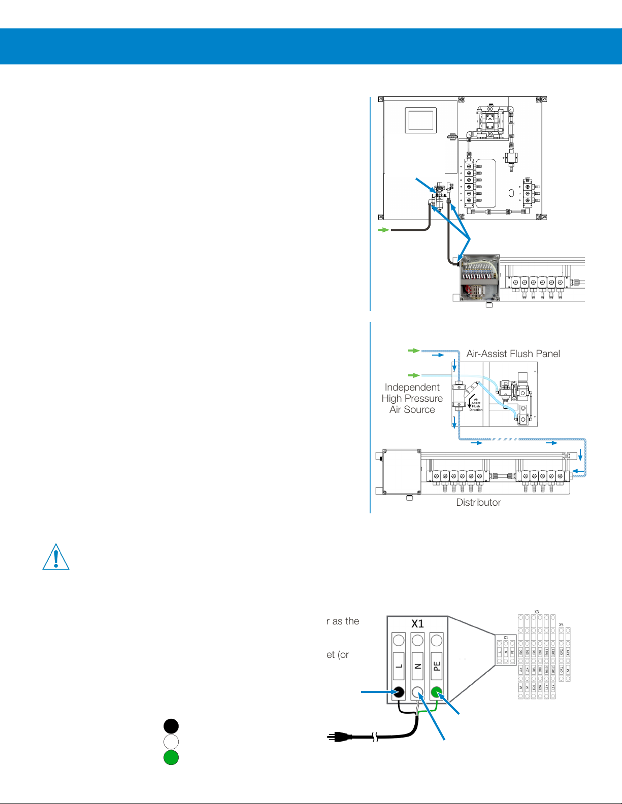
2.O3 Peripheral Elements
After placing the unit, it is necessary to mount the rest of the elements:
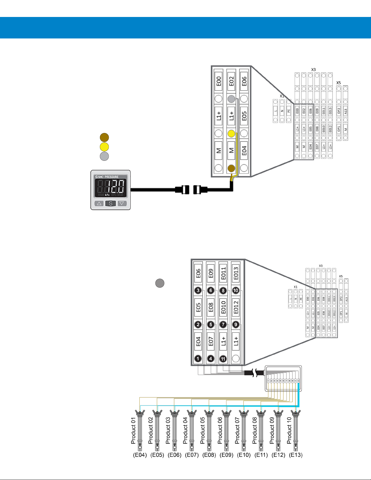
Distributor: This element is the responsible for diverting the products to the corresponding washer extractor. Only one
machine is attended while the others are queued. It is recommended to set the distributor at a position equidistant from the
washer extractors.
Calibration Vase: Since this vase is used for dosage calibration, it should be installed on the wall near the main panel.
Please note the vase is connected by a hose to the distribution manifold. Make provision for draining the calibration vase and
for overflow from the vent fitting.
Communication Boxes (machine signal interfaces): These elements are used to get the signals from the machines so they
can be acquired by the unit. There must be one box per washer extractor. The recommended position is a clear place on the
wall behind every machine.
2.OO installation
25.25”
35.25”
Note: Indicated Measurements are Approximate!

8
2.O4 Tubing
With all the components mounted, they can be connected with the
delivery hoses. A flexible, reinforced, transparent, chemically-compatible
hose of the proper inside diameter is recommended. On U.S. systems the
delivery hose connections are 1/2” barb and must be secured with worm-
gear hose clamps. Check the fittings on the washers and the chemical
drum pickup systems, in case an adapter will be required.
Water Inlet
The product delivery system will require water flow of about 1 to 2
gallons per minute (gpm) at a dynamic (valves open) water pressure
of 20 to 30 psi (1.5 to 2 bar). Do not use a water source that feeds other
equipment, if during that feed the flow or pressure drops below these
requirements.
Water of a higher pressure will require a pressure regulator before
the connection to the Dositec system. If necessary, install the appropriate
Hydro Systems Booster Tank to supply water at the proper flow and
pressure.
Chemical Pickup
Decide the best distribution for the tanks / drums of product.
After that, connect all tubes from the inlets at the unit’s manifold to the
suction lances. Please note the numbered order of the inlet valves, as
shown to the right.
Inlet Valve 1 = Water Inlet
Inlet Valve 2 = Product 1
Inlet Valve 3 = Product 2
Inlet Valve 4 = Product 3
Inlet Valve 5 = Product 4
Inlet Valve 6 = Product 5
Inlet Valve 7 = Product 6
Inlet Valve 8 = Product 7
Inlet Valve 9 = Product 8
Distributor Manifold Hoses
Install the delivery tubing from the main panel to the distributor inlet and
connect each distributor delivery tube to the appropriate washer, as
shown to the right. Note that a Distributor always has a final delivery valve
dedicated for the Calibration Vase. (A 10-washer Distributor is shown.)
Distributor Valve 1 = Machine 1
Distributor Valve 2 = Machine 2
Distributor Valve 3 = Machine 3
Distributor Valve 4 = Machine 4
Distributor Valve 5 = Machine 5
Distributor Valve 6 = Machine 6
Distributor Valve 7 = Machine 7
Distributor Valve 8 = Machine 8
Distributor Valve 9 = Machine 9
Distributor Valve 10 = Machine 10
Distributor Valve 11 = Calibration Vase
2.OO installation (continued)
Water
Inlet
Water valve
is always
first!
1/2” Tubing
1/2” Tubing
to Distributor
to Distributor
Product 1 Chemical Drum
From the
Main Panel
Machine 1
To the
Calibration
Vase
Products
W
2
9
3
8
7
Valves
Valves
Valves
Valves
P1
P2
P6
P7
P8
P5
P4
P3
6
6
54 10
3 9 V2 81 7
5
4

9
2.O4 Tubing (continued)
High Pressure Air Connection
Make sure there is sufficient air pressure, more than 60 PSI or 4 bar, but
not more than 120 psi or 8 bar.
Both the air line coming into the main panel regulator and the air line
running to the distribution manifold must be a 3/8” (12mm) outside
diameter plastic hose, and the fittings are a “push-in” design with no tools
required.
“Push twice” to get the hose past the sealing O-ring and the grip ring. The
hose can be soft or hard plastic, but the grip ring of the push-in fitting may
not hold with harder materials. To remove a hose from these fittings, push
the external ring toward the fitting to release the hose so it can be pulled
out. These fittings seal best when the hose goes “straight in”, not pulled at
an angle.
Once the main inlet is connected to the unit, set the regulator to 60 PSI
or 4 bar.
2.O5 Electrical Connections (110 VAC Main Power & Input / Output / Communications Connections)
Note: Do not power up the unit until ALL input, output and communications connections are connected!
Input: 110 VAC Main Power Connection
The 110 Volt AC power input must be an independent 3 wire supply and
a dedicated 10-amp breaker is recommended. Never use a washer as the
source for the input power supply!
The power cord must be plugged into a grounded three prong outlet (or
equivalent) using all three wires on Bank X1 as follows
:
• Phase – ‘L’ connector. (Black wire in U.S.)
• Neutral – ‘N’ connector. (White wire in U.S.)
• Ground – ‘PE’ connector (Green wire in U.S.)
1) Black Wire to L
2) White Wire to N
3) Green Wire to PE
Optional Air-Assist Flush
There are generally three reasons you might consider employing the
optional Air-Assist Flush Panel.
• A long distance to some or all of the washers (over 100 feet).
• Large dosage volumes of product to be delivered.
• When you have short duration washer cycles.
The advantage of the air-assist flush is a much faster dosage delivery than
the unassisted water flush.
The compressed air will push the product dosage to the washer very
quickly and also introduce much less water into the washer than would the
normal water flush.
2.OO installation (continued)
3 x Push-in Hose Fittings
(3/8 in or 12mm O.D.)
Incoming
Air Supply
60 - 120 psi
(4 - 8 bar)
Set
Regulator
to 0.4 MPa
(4 bar/60 psi)
Distributor
Main Panel
~~
~
~
Air-Assist Flush Panel
Delivery Hose
from Main Panel
Independent
High Pressure
Air Source
Distributor
“Hot” Black
Wire to L
“Ground” Green
Wire to PE
“Neutral” White
Wire to N
110-120 VAC
Grounded
Supply

10
2.O5 Electrical Connections (continued)
Input: Air Pressure Sensor Connection
If your system includes the optional Air Assist Flush feature, you
must connect the Air Pressure Sensor to the main panel on Bank
X3 at M, L1+ and E02 as shown below.
Remove the jumper/bridge wire from L1+ and E02. If the Air
Pressure sensor is not being connected, there must be a jumper/
bridge wire from L1+ to E02 or the system will go into alarm when
the air pressure test is performed.
1) Brown Wire to M
2) Yellow Wire to L1+
3) Gray Wire to E02
Input: Drum Level Sensor Connection
The Dositec Product Drum Lances have a built-in level sensor that
can tell the system if the chemical drum is empty.
You can have as many as ten of the level sensors connected to
the main panel, on Bank X3 using E04 through E13 and L1+ for
the common ground connection.
Wire supplied by installer, colors may vary.
Wire 1) Product 01 connects to E04
Wire 2) Product 02 connects to E05
Wire 3) Product 03 connects to E06
Wire 4) Product 04 connects to E07
Wire 5) Product 05 connects to E08
Wire 6) Product 06 connects to E09
Wire 7) Product 07 connects to E10
Wire 8) Product 08 connects to E11
Wire 9) Product 09 connects to E12
Wire 10) Product 10 connects to E13
Wire 11) Common ground always connects to L1+
2.OO installation (continued)
?

11
2.O5 Electrical Connections (continued)
Input: External Emergency Stop Connection
The contacts OP1 and OP2 on Bank X5 are configured for an External Emergency Stop function. It is a simple two- wire
resistance circuit, like a switch. When the circuit is closed (low resistance/continuity) the system operates normally. When the
circuit is open (high resistance/no continuity) the system will perform an Emergency Stop.
There is normally a jumper/bridge wire between OP1 and OP2 so the system will operate normally without an External
Emergency Stop device. Remove the jumper/bridge wire when using these connections.
Wire colors are dependent
on the device manufacturer
Output: External Alarm Indicator Connection
The Dositec’s main panel has a built-in alarm buzzer that is quite loud with a piercing sound, but it also has two contacts on
Bank X5, at A13 and M, that are designed to energize an additional, external alarm indicator.
The contacts are configured to supply 24 Volts DC, at up to 2 amps, to energize an external alarm indicator, like a strobe,
buzzer or bell.
1) Positive Connection to A13
2) Negative Connection to M
2.OO installation (continued)
?
?
OR
OR
OR
24V DC up
to 2 Amps
Device Wire
Colors May
Vary

12
2.O5 Electrical Connections (continued)
Output: Distribution Manifold Solenoid Connection
The PLC controls the solenoids in the Distribution Manifold through connections made on Bank X6, using A20 through A29
for chemical delivery to up to 10 washers, A210 for delivery back to the Calibration Vase, and M as a common ground for all
connections.
Note: The connector in the distribution manifold for the calibration vase solenoid is always marked “11”, even if less than
ten washers are being serviced.
Wire supplied by
installer, colors
may vary.
Output: Air Assist Flush Connection
The optional Air Assist Flush system is controlled by the PLC using the connections on Bank X6, at A215 and M, as shown
below.
1) Brown Wire to M
2) Green Wire to A215
2.OO installation (continued)
?
Distribution Manifold
Air Assist Panel

13
2.O5 Electrical Connections (continued)
Communication: Machine Communication Boxes
The Dositec’s Communication Boxes are the interface between the signals coming from the washer and the formula
programming to deliver certain products at certain times. The simple On/Off signals from the washer are translated into digital
packets of information and transmitted back to the Dositec PLC over a digital network. This allows a single four-wire cable to
daisy-chain from one communication box to another, which greatly simplifies installation.
The connection at the main panel is on Bank X8 at L1+, M, A and B as shown below. The four conductor cable runs to the
“In” connector of the box closest to the main panel. Any remaining boxes are connected with a cable running from the “Out”
connector to the “In” connector of the next box.
The boxes are identified to the PLC by the DIP switch settings as shown below. If you are using the Remote Formula
Selection accessory, their DIP switches must be set to match the Communication Box to which they are connected.
Communication: Machine Signals
The signal wires from each washer connect to their Dositec
Communications Box using the row of connectors at the lower
edge of the circuit board, with the grounds jumpered to have a
common connection, as shown to the right.
Communication: DIP Switch 5 - Auto-Formula Select Time
On the DIP switch that identifies the Communications Box (see
above), the fifth DIP switch is used to adjust the time period
for Auto-Formula Select (AFS).
With switch 5 in the Off position, 5 seconds is the AFS time, so
an AFS signal of 15 seconds would select Formula 3. With switch
5 in the On position, 3 seconds is the AFS time, so an AFS
signal of 9 seconds would select Formula 3.
2.OO installation (continued)
470 Ω
Resistor
Box 1 Box 2
InOut InOut
Other
Boxes
(If any)
= 1
= 2
= 3
= 4
= 5
= 6
= 7
= 8
= 9
= 10
Box Identification DIP Switch Settings
Every Box
Connection
(top down)
Brown
Yellow
Green
White
Washer
Signal
Wires
5 = Off
AFS time
is 5 sec.
5 = On
AFS time
is 3 sec.
Installer
supplied wiring,
color will vary!
1 2 3 4 5 6 7 8

14
(This page was intentionally left blank.)

15
When you have finished the physical installation of the system, you can begin the start-up procedure, detailed below:
3.O1 Configuring the System Settings
It is necessary to define all the parameters related to the unit, products, channels and washer extractors. Although you can do
this at the front panel, it is easier to use Hydro Connect to configure the unit remotely from a PC.
3.O2 Prime the Hoses that go to the Washer Extractors with Water
The hoses in the delivery channel and from the distribution manifold to the washers need to be filled with water. To do this,
use to the calibration screen and do successive ‘Water’ calibrations to each washer. Also fill the hose that comes back to the
calibration vase by selecting it as the destination. Check for leaks before proceeding to the next step.
3.O3 Prime the Suction Hoses of every Product
The hoses that run from product pick-up drum lances to the collection manifold on the main panel also need to be filled. Once
again use the calibration function but this time select ‘Product’ as calibration mode. You can send the flow to a washer or the
calibration vase, releasing the button to stop the dose as soon as the product hose is filled to the collection manifold. If you
are sending the flow to the calibration vase, open the valve at the bottom of the vase.
After each calibration you will be required to run a flush to clean the delivery channel. If you are sending the flow to
the calibration vase, watch out for an overflow when doing the flush. It is important to take into account the chemical
incompatibilities when choosing the order of the products to prime. If the delivery channel or vase is not sufficiently cleaned by
the flush, do a water calibration until you are satisfied.
3.O4 Calibration of Products
Now that all the hoses are primed, you can do the product calibrations. Select the Product whose delivery you wish to
calibrate in the calibration screen, and choose the calibration vase as the destination. Check that the valve at the bottom of
the calibration vase is closed. Press and hold the calibration button while sending the dosage to the vase. Remember that the
vase will begin to fill with water, not product, which is correct since the volume of water is the same as the volume of product
being pulled from the collection manifold.
Release the button to stop the dose when there is a representative sample in the vase (use the average of the maximum and
minimum dose for each chemical), check the volume scale on the side of the vase and enter the actual volume pumped on
the PLC touchscreen in milliliters.
3.O5 Calibration of Water
Although you could calibrate water delivery to the calibration vase, calibrating at the washer farthest from the main panel
provides the worst case scenario for pumping against back pressure. Put a bucket or other container at the inlet hose for
the washer, and hold the Calibration button down long enough to get a sizable volume delivered, like half a gallon (2 liters).
Carefully measure the volume of water that was delivered and enter that volume in the Actual field for the calibration in
milliliters.
3.O6 Check the Dosage Calibration with Manual Dose
To verify the flow meter measurements, perform a manual dosage to the calibration vase, with the Flush option set to “No”,
and with the valve at the bottom of the vase closed. Then confirm the volume in the vase is the same as the manual dosage
volume you entered on the PLC display. Since using the manual dose function to check the flow meter measurement must
be done with the vase valve closed and without flush, you will have to open the vase valve and flush the delivery channel as a
separate operation.
3.O7 Adjusting Flush Time for Each Washer Extractor
Use the Manual Dose function (with the Flush Option set to “Yes”) and send a dosage to each washer extractor. Choose a
product with a noticeable color, so you can watch at the inlet of the washer extractor and see if the current flush volume is
enough to take the full product dosage inside the washer. If the water flush volume needs to be adjusted, that is done on the
“Parameters of Washer Extractors” screen.
3.O8 Test the System
Run each washer one by one, and verify that the PLC is receiving all the washer’s signals, and responding with the proper
product delivery, based on the formula selected and the configuration for each wash phase. The number of the formula and
the corresponding phases must be reflected in the “View machines” screen.
3.OO system start-up

16
4.OO service parts
1
2
4
5
3
2
3
4
1
8
7
5 6
Schneider
HYD481712EST
3 Valve - Pneumatic Block HYD481713EST
HYD481714EST
2 Valve - Pneumatic Block
5 Valve - Pneumatic Block HYD481715EST
6 Valve - Pneumatic Block HYD481716EST
4 Valve - Pneumatic Block
2 Thermal Circuit Breaker HYD6153IDPN21643
HYD2940ABL8REM24050
HYD2953NSYTRV42SF5
1 Power Supply - 24V 5A
4 CPU - Model 241 PLC HYD2940TM241CEC24T
5 4 Input / 4 Output Module HYD2940TM3DM8R
6 16 Relay Output Modules HYD2940TM3DQ16R
7 Color Touchscreen 5.7” HYD2938HMISTU855
8 SD Memory 512MB for Schneider HYD2940TMASD1
3 2-Fuse Block Connector
Assy, Air Regulator, 1 Channel HYD1117210003
Flow Meter
1 Kit, Flow Meter Sensor HYD021713020002
HYD1318100FG4812PP2 Input Hose Fitting, 1/2”
HYD0217297301490
HYD02171432300
3 Kit, Paddlewheel & Base
4 Kit, PaddleWheel Only
HYD548084002995 Output Hose Barb, 1/2”
Kit, Replacement Pneumatic Pump HYD10099342
Pneumatic Solenoid Valve Blocks
M241 Pneumatic Wall-Mount Cabinet Components

17
4.OO service parts (continued)
1 Valve Block Hose Barb 1/2”
Pneumatic Solenoid Valve Block, Hose Barb, All
HYD54818400298
1
1
M241 Pneumatic Cabinet, Electric Air Valve, All
HYD481715LOUB1 Cabinet Electric Air Valve

18
5.O1 Limited Warranty
Seller warrants solely to Buyer the Products will be free from defects in material and workmanship under normal use and
service for a period of one year from the date of completion of manufacture. This limited warranty does not apply to (a) hoses;
(b) and products that have a normal life shorter than one year; or (c) failure in performance or damage caused by chemicals,
abrasive materials, corrosion, lightning, improper voltage supply, physical abuse, mishandling or misapplication. In the event
the Products are altered or repaired by Buyer without Seller’s prior written approval, all warranties will be void.
No other warranty, oral, express or implied, including any warranty of merchantability or fitness for any particular
purpose, is made for these products, and all other warranties are hereby expressly excluded.
Seller’s sole obligation under this warranty will be, at Seller’s option, to repair or replace F.O.B. Seller’s facility in Cincinnati,
Ohio any Products found to be other than as warranted.
5.O2 Limitation of Liability
Seller’s warranty obligations and Buyer’s remedies are solely and exclusively as stated herein. Seller shall have no other
liability, direct or indirect, of any kind, including liability for special, incidental, or consequential damages or for any other claims
for damage or loss resulting from any cause whatsoever, whether based on negligence, strict liability, breach of contract or
breach of warranty.
5.OO warranty
Hydro Systems
3798 Round Bottom Road
Cincinnati, OH 45244
Phone 513.271.88OO
Toll Free 8OO.543.7184
Fax 513.271.O16O
Web hydrosystemsco.com HYD90097621 Rev B 6/21
This manual suits for next models
7
Table of contents
Other Dover Washer manuals