DPS Telecom NetGuardian E16 DX G2 User manual

USER MANUAL
NetGuardian E16 DX G2
March 26, 2019 D-UM-X2E16 Firmware Version 1.0A
Visit our website at www.dpstelecom.com for the latest PDFmanual and FAQs.

© 2019 DPS Telecom
This document contains proprietary information which is protected by copyright. All rights are reserved. No part of this
document may be photocopied without prior written consent of DPS Telecom.
All software and manuals are copyrighted by DPS Telecom. Said software and manuals may not be reproduced, copied,
transmitted or used to make a derivative work, by either mechanical, electronic or any other means in whole or in part, without
prior written consent fromDPS Telecom, except as required by United States copyright laws.
The material in this manualis for information purposes and is subject to change without notice. DPS Telecomshall not be
liable for errors contained herein or consequentialdamages in connection with the furnishing, performance, or use of this
manual.
Notice
Revision History
Updated Specifications
Updated shippinglist
Added note that LAN is for testing or firmware upgrades
Initial Release
March 26, 2019
August 31, 2017
September 26, 2014
March 25, 2014

Contents
Overview1 1
Shipping List22
Specifications3 3
Front Panel Connections44
Rear Panel Connections54
LAN Connection64
Hardware Installation75
Tools Needed7.1 5
Mounting7.2 6
Power Connection7.3 6
Communication Lines7.4 7
Alarm and Control Relay Connections7.5 8
Connecting via the USB port810
Bypass Password916
Setting the DCP Address10 16
Updating Firmware with dsPICLoader11 17
Updating Firmware via the web12 18
Operations13 19
Front and Rear Panel LEDs13.1 19
Provisioning Menu14 20
System14.1 21
Ethernet14.2 22
Monitoring via Web Browser15 23
Alarms15.1 23
Controls15.2 24
Device Access Descriptions16 25
Technical Support17 26
End User License Agreement18 26

1
Overview1
Fig. 1. The NetGuardian E16 DXG2
Discrete Alarm and Control Relay Expansion Solution
The NetGuardian E16 DXG2 expands the capacity of the NetGuardian 832 G5 platform (including the 864A) by 16
alarm points and 16 controls.
The E16 DXG2 interfaces to either:
·An RS232 serial ports on the NetGuardian 832A G5 that is configured for point expansion, or
·An RS232 serial port on a NetGuardian 864 DXthat is already daisy-chained onto a base NetGuardian.
NOTE: Only a single E16 DXG2 may be connected to a base NetGuardian, and it must be the last expansion in a
daisy chain. Because the E16 DXG2 has only an input serial port and no output serial port, it can only attach itself
to the end of a chain.
Fig. 2. An expanded RTU. The NetGuardian 864A G5 (top) has been supplemented by 2 NetGuardian 864DXunits
(middle) and a NetGuardian E16 DXG2 (bottom). This configuration has a total of 208 alarm inputs and 40 control
relays. Both of the 864DXunits are optional expansions.
Dual, separately fused -48V power
For protection against power failures, the NetGuardian E16 DXfeatures dual redundant -48vdc power supplies.

2
Shipping List2
While unpacking the NetGuardian E16, please make sure that all of the following items are included. If some parts
are missing, or if you ever need to order new parts, please refer to the part numbers listed and call DPS Telecom at
(800) 622-3314.
NetGuardian E16 DX G2 NetGuardian E16 DX G2 User Manual
D-PK-X2E16 D-UM-X2E16
RJ45 to RJ45 connection cable USB Cable
D-PR-1028-10C-00 D-PR-046-10A-06
23" Rack Ears 19" Rack Ears
D-CS-325-10A-01 D-CS-325-10A-00
x8 X 4
3/8" Ear Screws & Washers Standard Rack Screws
2-000-60375-05 1-000-12500-06
X 4
Metric Rack Screws Pads
2-000-80750-03 2-015-00030-00
x3 X 2
3/4 -Amp GMT Fuse Locking Power Screw Lug Barrier Plugs
2-741-00750-00 2-820-35102-00
Cable Ties

3
Specifications3
Dimensions: 1.7" H x 17.0" W x 6.6" D
Weight: 2.25 lbs.
Mounting: 19" rack, 23" rack, or wall mounting
Power Input: –48VDC (–18 to –72 VDC)
Current Draw: 250 mA
Fuse: (2) 3/4 Amp GMT
Operating Temperature: 32° – 140° F (0° – 60° C)
Operating Humidity: 0%–95% non-condensing
Interfaces: Two 50-pin connectors for discrete alarms and control relays
1 RJ45 Ethernet jack (not used)
1 RJ45 RS-232 jack
1 USB craft port
Protocols: DCPx, 2400 baud
Discrete Point Inputs: 16 inputs
Control Outputs: 16 relay contacts
Visual Display: Dual and Mono Color LEDs

4
Front Panel Connections4
Fig. 3. The NetGuardian E16 DXG2 Front Panel Controls
The craft port, Ack, and LED displays are accessed via the front panel, as seen in Figure 3.
Rear Panel Connections5
Fig. 4. NetGuardian E16 DXG2 rear panel connections
Connectors for power feeds, alarm inputs, control outputs, and communication lines are on the back panel of the
NetGuardian E16, as shown in Figure 4.
LAN Connection6
To connect the unit to LAN, insert a standard RJ45 Ethernet cable into the 10/100BaseT Ethernet port on the back
of the unit. If the LAN connection is OK, the LNK LED will light SOLID GREEN. The LAN connection may be used
for upgrading the firmware or testing but is not required for the equipment to function properly.

5
Hardware Installation7
Follow this order of steps when installing your NetGuardian E16.
1. Unpack the NetGuardian E16 DX G2 and check parts.
Please see the shipping list to verify that all parts were included in your shipment.
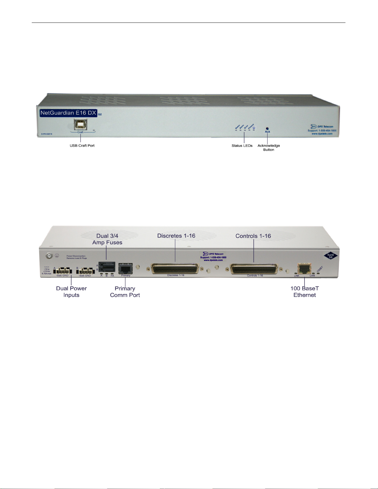
2. Mount the NetGuardian E16 DX G2.
The NetGuardian E16 can be mounted in a 19" or 23" rack.
3. Connect power leads to the NetGuardian E16 DX G2.
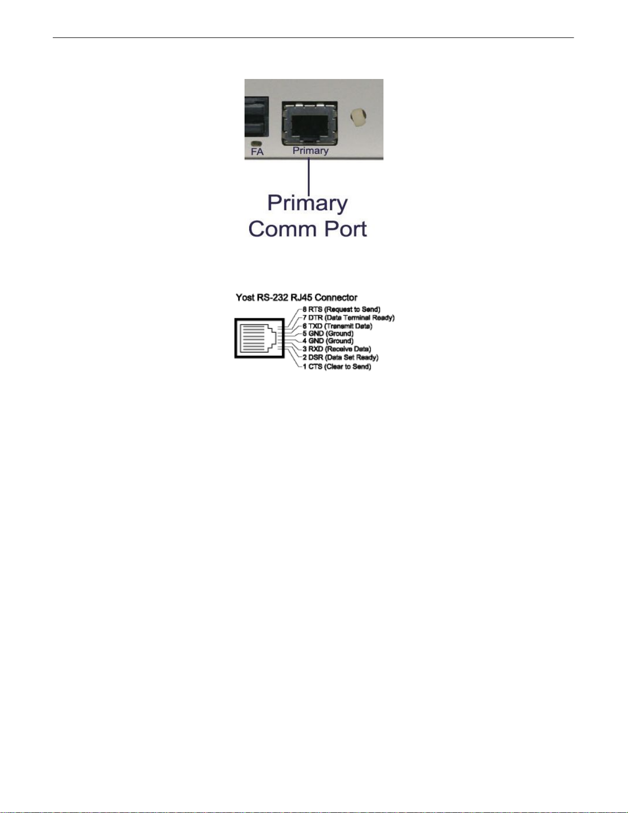
4. Connect communication lines to the NetGuardian E16 DX G2.
The NetGuardian E16 has one communication line: a RS232 serial port
5. Connect discrete alarm inputs.
6. Connect control outputs.
7. Connect to the NetGuardian 832 or 864 G5.
You can connect to the NetGuardian E16 DX G2 through the front panel craft port. Please note that the NetGuardian
E16 DXG2 must be the last unit in the chain.
8. Provision the NetGuardian E16 DX G2 and 832A G5.
The NetGuardian E16 DXG2 must be provisioned with a DCP address using the TTY interface via Craft Port
connection. You must provision the NetGuardian 832A G5 to specify the "E16" as the DXtype.
Tools Needed7.1
To install the NetGuardian E16, you'll need the following tools:
Phillips No. 2 Screwdriver Small Standard No. 2 Screwdriver
Wire Strippers/Cutter Computer with terminal software or web browser

6
Mounting7.2
Fig. 5. The NetGuardian E16 DXG2 can be flush or rear-mounted.
The NetGuardian E16 DXG2 can be mounted in a 19" rack or a 23" rack by using the provided rack ears for each
size. Two rack ear locations are provided. Attach the appropriate rack ears in the flush-mount or rear-mount
locations shown in Figure 5.
Note: Rack ears can be rotated 90° for wall mounting or 180º for other mounting options not shown.
Power Connection7.3
To connect the NetGuardian to a power supply:
Battery lead left, and Ground right
Grounding Lug left, dual power inputs right
1) Insert a battery ground wire into the connector's right terminal (Shown above) and battery lead into
the left terminal and tighten the screws. Insert the connector into the power plug. Attach a grounding
wire to the grounding lug .
2) Ensure the power status LED is lit up green for correct polarity.
3) Insert the local fuse into the fuse holder.
4) The front panel status LED should flash RED and GREEN to indicate that the unit is operating.
Note: Always use safe power practices when making power connections. Make sure the power wires are
not active before making any power connections

7
Communication Lines7.4
Fig. 7
Serial Port is in the lower right corner of the NetGuardian E16 DXG2's back panel, as shown in Figure 7.
Fig. 8. Serial Port Pinouts

8
Alarm and Control Relay Connections7.5
Fig. 9. Alarm and control relay connectors.
Discrete alarms and control relays are connected to the NetGuardian E16 DXG2 using the two 50-pin connectors on
the back panel, shown in Figure 9. Pinouts for all connections are shown in Figure 10, and alternately in Table A.
Fig. 10. Alarm and control connection pinouts.

9
Alarms
1
-16
Controls
1
-16
Pin #
Pin #
Pin #
Pin #
GND
1
AM1
26
CT 1 NC
26
CT 9 NC
38
GND
2
AM2
27
CT 1 NO
1
CT 9 NO
13
GND
3
AM3
28
CT 1 CO
27
CT 9 CO
39
GND
4
AM4
29
CT 2 CO
2
CT 10 CO
14
GND
5
AM5
30
CT 2 NC
28
CT 10 NC
40
GND
6
AM6
31
CT 2 NO
3
CT 10 NO
15
GND
7
AM7
32
CT 3 NC
29
CT 11 NC
41
GND
8
AM8
33
CT 3 NO
4
CT 11 NO
16
GND
9
AM9
34
CT 3 CO
30
CT 11 CO
42
GND
10
AM10
35
CT 4 CO
5
CT 12 CO
17
GND
11
AM11
36
CT 4 NC
31
CT 12 NC
43
GND
12
AM12
37
CT 4 NO
6
CT 12 NO
18
GND
13
AM13
38
CT 5 NC
32
CT 13 NC
44
GND
14
AM14
39
CT 5 NO
7
CT 13 NO
19
GND
15
AM15
40
CT 5 CO
33
CT 13 CO
45
GND
16
AM16
41
CT 6 CO
8
CT 14 CO
20
17
42
CT 6 NC
34
CT 14 NC
46
18
43
CT 6 NO
9
CT 14 NO
21
19
44
CT 7 NC
35
CT 15 NC
47
Lk DN NO
20
Lk DN CO
45
CT 7 NO
10
CT 15 NO
22
21
46
CT 7 CO
36
CT 15 CO
48
22
47
CT 8 CO
11
CT 16 CO
23
23
48
CT 8 NC
37
CT 16 NC
49
FANO
24
FACO
49
CT 8 NO
12
CT 16 NO
24
GND
25
GND
50
GND
25
GND
50
Table A. Alarm and Control connection pinouts.

10
Connecting via the USB port8
The NetGuardian E16's front panel USB craft port.
1. The simplest way to connect to the NetGuardian is over a physical cable connection between your
PC's USB port and the unit's USB craft port. Note: You must be connected via craft port or Telnet
to use the TTYinterface. Make sure you are using a standard A-B USB cable (this same cable is
commonly used for USB printers) to make a USB craft port connection. We'll be using
HyperTerminal to connect to the unit in the following example - however, most terminal-emulating
programs are also compatible.
When you first connect the NetGuardian to your PC via USB, a "Found New Hardware" message will
appear:
1. Click the "Found New Hardware" message/icon to launch the "Found New Hardware Wizard".

11
2. Select "Install from a list or specific location (Advanced)"
3. Click "Next >"
4. Select "Search for the best driver in these locations."
5. Insert NetGuardian Resource Disc (CD) into your PC.
6. Click "Browse"

12
7. Select the "Driver" folder of your NetGuardian Resource Disc (CD) and click "OK"
The following message will confirm installation of a new "USB Communications Port"
8. Click "Finish" to close the Wizard.
Now that the driver has been installed, a new COMport is being emulated on your PC. Before using
hyperterminal, you must confirm the identity of that new COMport (COM1, COM2, COM3...) in the
Windows Device Manager.

13
9. Right-click the "My Computer" icon on your desktop, then click "Manage"
10.Click "Device Manager" in the left pane.

14
11.Expand the "Ports (COM& LPT)" section in the right pane. Look for "USB Communications Port
(COMx)". Note the number of the COMport ("COM3" in the example above).
Now that you know which COMport to use, it's time to launch HyperTerminal (or other terminal
software):
12.Click on the Start menu > select Programs > Accessories > Communications >
HyperTerminal.
13. At the Connection Description screen, enter a
name for this connection. You may also select an
icon. The name and icon do not affect your ability
to connect to the unit.
14. At the Connect To screen, use the drop-
down menu to select the COMport you found
earlier in the Device Manager.

15
15. Select the following COMport options:
• Bits per second: 9600
• Data bits: 8
• Parity: None
• Stop bits: 1
• Flow control: None
Once connected, you will see a blank, white
HyperTerminal screen. Press Enter to activate
the configuration menu.
16. When prompted, enter the default user
name admin and password dpstelecom.
NOTE: If you don't receive a prompt for your
user name and password, check the Com port
you are using on your PC and make sure you
are using the cable provided. Additional cables
can be ordered from DPS Telecom.
17. The NetGuardian 's main menu will appear.
Type C for C)onfig, then E for E)thernet. Configure
the unit's IP address, subnet mask, and default
gateway.
18. ESC to the main menu. When asked if
you'd like to save your changes, type Yfor Y)es.
Reboot the NetGuardian to save its new
configuration.

16
Bypass Password9
Hold button while unit is booting up to bypass password in the event of a forgotten password.
Setting the DCP Address10
To set the DCP address on the NetGuardian E16 DXG2, connect to the TTY interface.
Note: The default DCP address is '1'. Most likely you will not need to change this.
To connect to the TTY interface, connect a serial port on your PC to the front craft port on the E16 DXG2 using
the included USB cable.
Use terminal software such as Hyperterminal or PuTTY to establish a connection (9600 baud).
Fig. 13 - The procedure for setting the DCP address on the NetGuardian E16 DX G2 via the TTY interface.

17
Once the TTY connection has been established,
1. Login using admin; dpstelecom
2. Press 'C' for Configure
3. Press 'D' for DCP
4. Type '1', '2', or '3' to set the DCP address to 1, 2, or 3. The address will be displayed.
5. Reboot the E16 DX to activate the new address
Updating Firmware with dsPICLoader11
Fig. 14. dsPICLoader screen
To update the NetGuardian E16 DX G2 firmware using dsPICLoader with firmware you have downloaded from
dpstele.com, follow these steps:
1. Connect to the USB Port (See: Connecting via the USB port)
2. Select a task file by clicking the browser button next to the Select File: box.
3. Click the Start button. The firmware upgrade will be automatically uploaded to the NetGuardian E16 DX G2.
While uploading, the dsPICLoader screen will display the elapsed time and throughput of the upload to the
NetGuardian E16 DX G2.
4. Once the firmware upload is finished, click the X to exit dsPICLoader.
Table of contents