Dulas Solar VC150 User manual


2
CONTENTS:
Page
SECTION I
Dulas Solar Powered VC150 Refrigerator/Freezer
Installation & Operation Manual
………….
1 to 26
SECTION II
Fault Finding & Repair of
Photovoltaic Refrigerators
… ……
1 to 100
SECTION III
A User Handbook For
Photovoltaic Refrigerators…………… 1 to 23

3
SECTION I

4

5
CONTENTS
SECTION Page No.
KNOW YOUR SYSTEM
Component checklist 3
Battery safety 4
Preparation 5
Completed system 6
SOLAR ARRAY
Photovoltaic module assembly 7
Support structure orientation 8
Support structure assembly 10
Lightning protection 12
ELECTRICAL SYSTEM
Photovoltaic controller information 13
Photovoltaic controller installation 14
Battery commissioning 15
THE REFRIGERATOR/FREEZER
Positioning and starting 1
Loading 21
Single fridge controller settings 22
Routine maintenance 23 & 24
SYSTEM DIAGRAMS
Photovoltaic module and battery wiring 25
Diagrams
System wiring diagram 26
Refrigerator general layout 27
Electrical circuit diagram 28
Refrigeration circuit diagram 29

6
COMPONENTS-CHECK LIST
REF
PRODUCT QUANTITY
SOLAR ARRAY
a.1 KD135 solar modules 2
a.2 10m array output cable 1
a.3
0.5m module
Interconnect cable assembly
1
a.4
Bolt, plain washer, Nylon washer,
Penny washer & Nut
Pack
a.5 Silicon Sealant 1
REFRIGERATOR
b.1 DULAS VC150 refrigerator/
Freezer
1
b.2 Refrigerator cable 1
SUPPORT STRUCTURE
c.1
Unirac rail
c.2 Unirac high profile tilt leg kit 2
c.3 Feet 4
c.4 Bolt, plain washer, spring washer &
nut
Pack
c.5 Screws & wall plugs Pack
c.6 Cable clips
BATTERY PACK
d.1 Battery 1
d.2 Battery box 1
d.3 Photovoltaic controller 1
d.4 Battery to controller cable 1
d.5 Spare fuses 3
d.6 Cable ties Pack
d.7 Padlocks 2
TOOLS REQUIRED FOR INSTALLATION
Pozidriv No.2 Screwdriver Slot-head Screwdriver
Pliers Wire Cutters
Wire Strippers Craft Knife
Drill and Bits Hammer & Punch
Adjustable Spanner Size10, 11, 13, 14 & 17mm Spanners

7
BATTERY SAFETY
Observe operating instructions and position them within
sight of battery! Work only on batteries under instruction of skilled personnel!
The electrolyte (diluted sulphuric acid) is extremely corrosive. When
working on batteries wear safety glasses and protective clothing.
Acid splashes in the eyes or on the skin must be washed out or off with
plenty of water. Then see a doctor immediately. Clothing exposed to
acid should be washed out with water without delay.
Electrical danger! In the case of short circuit, extremely high currents
can occur which can cause severe burn.
Block batteries or cells are heavy! Ensure secure installation! Only use
suitable transport equipment!
Explosion and fire hazard due to explosive gases escaping from the
battery. Caution! Metal parts of battery are always live; therefore do not
place items or tools on the battery! Avoid short circuits!
No Smoking! Do not expose the battery to an open flame; a glowing
fire or sparks as explosion and fire hazards exists.

8
KNOW YOUR SYSTEM
PREPARATION
Before connecting, some time should be dedicated to working out all the aspects
concerned in the system installation.
By following these simple instructions and spending a little time on each, the whole
installation process should be easier.
1) Check that all components are present, familiarize yourself with them and make
sure that everything has been identified.
2) Discuss and decide a position for refrigerator, ensuring that it is well ventilated,
dry and not in direct sunlight. The colder the room, the better the performance.
3) Work out a position for the solar array ensuring that it faces the correct direction,
is at the correct tilt angle (see page on support structure orientation), no shading
will occur, it will not be damaged and it is accessible for cleaning and
maintenance.
4) Work out the route for the solar array output cable, ensuring that there is
sufficient length to reach the charge regulator.
5) Choose a position for the batteries that is well ventilated, dry, safe, not in direct
sunlight and accessible for topping up with distilled water. The colder the room
the better the performance.
The system when completely installed should look similar to the drawing below.
Each component should have a sensible, well thought out, safe location, allowing
access for routine maintenance.
KNOW YOUR SYSTEM
KNOW YOUR SYSTEM
COMPLETED

9
KNOW YOUR SYSTEM
COMPLETED
SOLAR MODULE ARRAY
SUPPORT STRUCTURE
CHARGE REGULATOR
BATTERY PACK
REFRIGERATOR
SOLAR ARRAY ACCESS
GOOD VENTILATION
NO DIRECT SUNLIGHT ON REFRIGERATOR
1
2
3
4
5
6
7
8

10
SOLAR ARRAY
KYOCERA MODULE ASSEMBLY
PLEASE READ ALL INSTRUCTIONS THOROUGHLY BEFORE COMMENCING
(FOR 12V WIRING LAYOUTS SEE ‘JUNCTION BOX WIRING DIAGRAMS’)
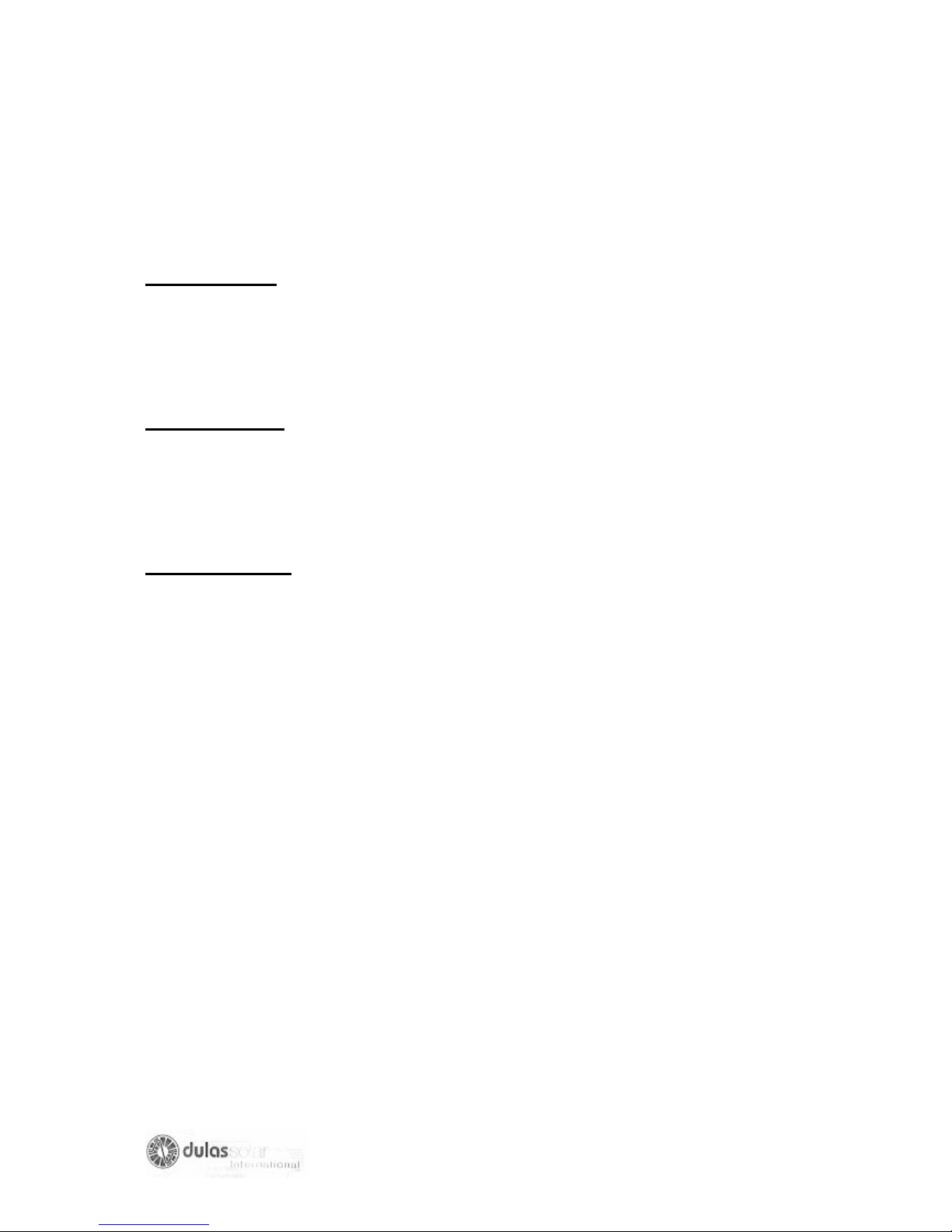
After insuring that all the components are present, remove the
solar (module a.1) from their cardboard boxes and lay them next
to each other on top of the cardboard, with glass facing down.
Do not step on the glass module. BROKEN MODULE CANNOT
BE USED. Arrange the solar modules so that the junction boxes
are all on the same side.
Interconnected the modules with the cables provided (a.3). The
interconnected cable has a crimped ring terminal at each end
which are easily connected to the Kyocera junction boxes as
illustrated below in figure1, (remove plastic unit, screw gland in
place, replace plastic nut and connect cable.)
The array output cable (a.2) must then be connected to the
nearest module (see system wiring diagram), brown or red wire
to +, blue or black wire to -. Ensure that there is sufficient cable
to meet the necessary distance then insert into the junction
boxes as performed previously.
Note: Due to New cable color regulations brown or red can be
used for + ve and blue or black for – ve until 1/4/06 after which
time only brown and blue will be permissible.
Lift the cover of the junction box by removing the four screws.
Place the ring terminal into position and tighten up the terminal
screw until it is gripped securely. Replace the cover of the
junction box with the screw provided ensuring a moisture proof
seal.

11
SUPPORT STRUCTURE
ORIENTATION
The solar array must be permanently positioned where the module will receive the
maximum amount of sunshine, however they are very fragile and should not be
located where they may be damaged. A suitable position must be found away from
trees and tall objects, to avoid shading the array, as this will impair the performance
of the module.
Please ensure that the support structure is:
SECURE AND NOT TWISTED
ACCESSIBLE FOR CLEANING
WELL VENTILATED
SAFE FROM SEVERE WEATHER CONDITIONS
NOT SHADED (BETWEEN 7am & 5 pm)
The solar array should face towards the equator- i.e.
South in the Northern Hemisphere,
North in the southern Hemisphere.
The tilt angle of a solar array is dependent on the country in which it is located.
Figure 3 demonstrates common tilt angles. The front of the solar modules must be
cleaned every week or when necessary in dusty Ares.
SUPPORT STRUCTURE
ORIENTATION CONTINUED

12
SUPPORT STRUCTURE
ORIENTATION CONTINUED
The support structure is made from pre-drilled galvanized steel angle. If you
mounting area cannot be level e.g. you have a sloping roof, then adjusting the foot
mounting holes must make the correct angle.
Use the ratios below to calculate your appropriate angle and follow the diagram to
position the structure accurately.
Required angle (A)
Approx. ratio (x:y) Required Angle (A) Approx. ratio(x: y)
10
0
6:1
30
0
2:1
15
0
4:1
35
0
1.75:1
20
0
3:1
40
0
1.5:1
25
0
2.4:1
45
0
1.4:1
Changing the position or length of the Tilt legs
can alter module angles.
Always ensure that all bolts are secured
tightly after alterations have been made.
A protractor can be used to determine
if the correct angle has been acquired.

13
SUPPORT STRUCTURE
ASSEMBLY
1. Assemble the Unirac TLH High Profile tilt Legs as shown in the drawing below.
The UniRac can easily be assembled in any order appropriate to the job site
requirement.
2. Use 3/8” hardware to assemble the UniRac and ¼” hardware to attach the PV
modules to the UniRac
3. UniRac must be securely attached to roof rafter, ground footing or other secure
structural feature. Simply screwing the UniRac to roof decking is not adequate to
withstand high wind loads.
4.leaving as much space as possible at the bottom of the UniRac will minimize
debris accumulation and snow load.

14
SUPPORT STRUCTURE
LOCATING MOUNTING FEET
5. The drawing below shows two options for setting the width of the Mounting feet. If
possible, mount a PV module to the UniRails to determine the best attachment
method for ontaining the proper distance between the mounting feet.
TILT LEG
6. On UniRacs Tilt Leg Kits, rack tilt can be determined by
A- raising or lowering the Tilt Leg
B- Moving the Tilt leg up or down alog the UniRails,
C-Adjusting the distance between the lower and upper Mounting feet before
final installation.
COMPLETED UNIRAC TLH HIGH-
PROFILE TILT LEGS INSTALLATION
(ADJUSTABLE LEG
)

15
LIGHTNING PROTECTION
MEASURES
LEVEL 1-NO PROTECTIVE MEASURES-NOT RECOMMENDED BY DULAS LTD
Failure to provide protection measures against lightning strike risks damage to the
equipment. In the event of lightning strike the roof mounted solar array, high voltage
may be conducted towards the refrigerator system. This high voltage may damage
the electronic components of the system.
LEVEL 2-LIMITED PROTECTIVE MEASURES (Normally Supplied)
We strongly recommend that at least this level of protection be installed-see figure 1.
Install an earth electrode (earth rod)(A) outside the building-the earth rod should be
at least 2m long. Connect the earth rod with good quality wire (at least 6mm
2
) to
battery positive (wire B) and with separate similar wire to the Solar array and support
structure (wire C). The earth wire should follow the shortest and straightest path
between the support structure and the earth rod.
LEVEL 3- FULL LIGHTNING CONDUCTOR SYSTEM (Not Supplied)
Assess the risk of lightening strike. Look at other local building- are they fitted with
lightening conductors? Ask local people if TV aerials etc often get struck?
If the installation is at high risk of lightening strike then an additional lightening
conductor and separate earth rod should be installed-see figure 2.
In addition to level 2 protections, install a second earth electrode (D). The distance
between the two earth electrodes must be more than their length. Erect an Air
terminal of Lightning Conductor (E) next to the second earth electrode. The Air
terminal must exceed the height of the Solar Array such that the Solar Array falls
within 45
0
cone centered on the Air terminal-this is the area that is protected by the
Air Terminal.

16
PHOTOVOLTAIC CONTROLLER
INFORMATION
When using Lead-Acid batteries in photovoltaic systems it is important to protect
them against overcharging which would otherwise cause excessive gassing and
overheating, resulting in permanent plate damage and loss of electrolyte. The
Photovoltaic Controller is installed into the system to perform this task. Over –charge
prevention is achieved by limiting the battery voltage to a maximum of around 2.3
Volts per cel at 25
0
c.This cause the charging current to fall naturally before gassing
becomes a problem. The battery can be left charging at this ‘float’ voltage for long
periods with minimal electrolyte loss. A periodic equalization charge is given to avoid
plate sulphation and electrolyte stratification. The battery float voltage is temperature
compensated. In order to measure temperature, a temperature sensor is built in to
the controller. The controller should therefore be mounted as close as possible to the
batteries.
The controller also has an automatic low voltage disconnect facility. In the event of
the batteries not receiving charge, the refrigerator will be disconnected before
permanent battery damage occurs, thus protecting system. Re-connection is
automatic. A Liquid Crystal Display (LCD) indicates the state of charge of the
batteries, and terminals are provided for the connection of batteries, photovoltaic
panels and the refrigerator.
OPERATION
The Photovoltaic Controller is fully automatic in operation. See Steca manual for
installation.
REGULAR FUNCTIONS
The display widow on front panel shows system and error message, the left button
on front panel can be used to switch display windows or calling up settings and the
right button is used as a manual load switch, or confirmation button in the
programme mode. The three displays, which are the most relevant to the operation
of the refrigerator, are as follows:
1. CORRECT OPERATION: Indicated by a smiling face in the display window. A sad
face indicates a fault. The reference number in the display can then be looked up in
the manual to give the meaning of the error and the cause/remedy.
2. STATE OF CHARGE: Indicated by the bar graph (SOC) and a percentage on the
display. When the state of charge is 50% or less, icepacks should not be frozen.
3. LOAD DISCONNECTION: The refrigerator is disconnected when the state of
charge drop to 30%. The SOC bar value, or the voltage value, flashes. The face
looks sad until the reconnection set point is reached.
THE LCD ALSO PERFORMS VARIOUS OTHER FUNCTIONS. CONSULT THE
MANUFACTURER’S HANDBOOK FOR FURTHER INFORMATION.

17
PHOTOVOLTAIC CONTROLLER
INSTALLATION
The unit should be installed in a dry location with clear space around it, to allow heat
generated at the rear of the unit to be dissipated. The unit is fixed to the wall so that
the terminals are at the bottom and the fins running vertically.
Installation instructions
1. Fix the Photovoltaic Controller to the wall with plugs and screws.
2. Connect the battery cable to the central pair of terminal on the unit (2). Taking
care to ensure correct polarity (brown or red to +, blue or black to -).
3. The array output cable (a.2) must be connected AFTER the batteries, to the left
hand pair of terminal on the unit (1) (brown or red to +, blue or black to -). BE
AWARE OF LARGE VOLTAGES. Cover the array or connect at night.
4. The refrigerator is connected to the right hand pair of terminal (3) on the regulator,
taking care to ensure correct polarity (brown or red to +, blue or black to -).
5. Support the cables using the clips provided.

18
COMMISSION THE BATTERIES
CONNECT THE BATTERIES
THE BATTERY BOX MUST ALWAYS BE LOCATED IN A VERY WELL
VENTILATED AREA AS THE BATTERIES GENERATE HYDROGEN, WHICH IS
AN EXPLOSIVE GAS.
1. After choosing a final location, carefully place
batteries into the empty box, ensuring not to
lift by the terminal points. THE BATTERIES
ARE NOW EXTREMELY HEAVY.
2. Connect the battery –to-regulator cable to the regulator
FIRST, brown or red to + and blue to – THEN to the
battery. Secure in place using the nuts, bolts and
washers provided. Insert a spare fuse (d.7) into the
fuse holder on the battery-to-regulator cable. Any
problem refers to the manufacturers handbook
provided.
3. Apply petroleum jelly or similar to each battery
terminal-this help avoid corrosion.
4. Commence charging of the batteries immediately by
connecting the solar array cable to the PV controller.
DO NOT CONNECT THE REFRIGERATOR, as the
batteries need an initial charging of two sunny days for
optimum performance.
5. Once the batteries are ready for operation (after two
good sunny days of charging), the refrigerator can be
connected.

19
THE REFRIGERATOR /FREEZER
POSITIONING
DO NOT POSITION THE VC150 REFRIGERATOR/FREEZER IN DIRECT
SUNLIGHT.
ENSURE THAT THE REFRIGERATOR IS WELL VENTILATED, ESPECIALLY
THE VENTILATION GRILLS AND CONDENSER.
WE RECOMMEND LEAVING a 500mm GAP AT EACH END OF THE
REFRIGERATOR
NEVER OBSTRUCT THE TEMPERATURE OR REGULATOR DISPLAYS
ENSURE THAT THE BATTERY BOX AND BATTERIES CAN BE INSPECTED
WHEN NECESSARY
NEVER BLOCK THE CIRCULAR COMPRESSOR VENTILATION FAN AT THE
FRONT
STARTING THE FRIDGE
The VC150 refrigerator is designed for continuous operation, therefore an ON/OFF
switch is not provided, as it is not necessary. The VC150 Freezer however, does not
an ON/OFF switch to allow for defrosting? This is situated at the rear right of the
cabinet, as viewed from the front, above the cable gland (see General Layout
diagram)
The VC150 refrigerator/freezer is operational when the power cable is connected to
the controller.
a) Strip the power cable to reveal 10 mm of brown or red (+) and blue or black (-)
wire.
b) Insert the cable into the black strain relief gland, located at
the rear, see ‘Cable Entry’ in the General Layout Diagram.
.
c) Connect to + & - terminals
on opposite side of the
strain relief gland
.
.
d) TIGHTEN THE TERMINALS SECURELY, TIGHTEN
THE STRAIN RELIEF GLAND SECURELY.

20
THE REFRIGERATOR/FREEZER
LOADING
IN ORDER TO KEEP INTERNAL TEMPERATURE OPTIMUM AND MINIMISE
ENERGY CONSUMPTION ONLY OPEN THE LID WHEN STRICTLY NECESSARY
AND ALWAYS REPLACE INNER FOAM LIDS
The VC150 refrigerator /freezer has two components, see General layout Diagram:
1) The smaller freezer (ice pack) compartment to left.
2) The larger refrigerator (vaccine) compartment to the right.
ICE PACKS: When frozen ice packs are needed; switch the freezer ON, insert ice
packs with basket into the LEFT compartment. Ice packs must be in contact with the
freezer compartment walls for effective freezing. A wire basket is provided to hold
the ice packs against the walls of the compartment. Only three sided of the
compartment can be used for freezing ice packs as the fourth has the thermostat
sensor mounted on it. A small wire cage protects the sensor. Simply simply reaching
inside the basket, and sliding the ice packs up and out of the ice freezing area
remove ice packs. Frozen ice packs can be stored in the space inside the wire
basket. The freezer can freeze nine ice packs simultaneously. Remember to switch
freezer OFF when not in use – to save energy.
WARNING: STANDARD SYSTEMS ARE DESIGNED TO ONLY FREEZE 2.4 KG’S
OF ICE PER 24 HOURS, FREEZING MORE WILL FLATTEN THE BATTERIES.
VACCINES: The refrigerator compartment situated to the RIGHT is in constant
operation. The wire baskets in the refrigerator compartment are designed to prevent
the contents of the compartment from touching the cold sides, and to encourage the
circulation of air. Good air circulation will help the refrigerator to maintain an even
temperature throughout the compartment. The contents of the compartment should
be arranged to allow good air circulation. In order to save energy, try to keep the lid
open for as short a time as possible. Try to allocate a certain space for each different
type of vaccine, so that they may be located rapidly. Check the vaccine labels and
adhere to any special requirements, always use before expiry date (store older
vaccines on top).
WARNING: ALWAYS FOLLOW THESE VACCINE STORAGE GUIDELINES
Other manuals for VC150
1
Table of contents
Other Dulas Solar Refrigerator manuals