Dvorak SPIDER MINI II User manual

2/ 102 SM-8 Ev3/08072015
SPIDER MINI
TECHNICAL SPECIFICATIONS ...................................................................................................3
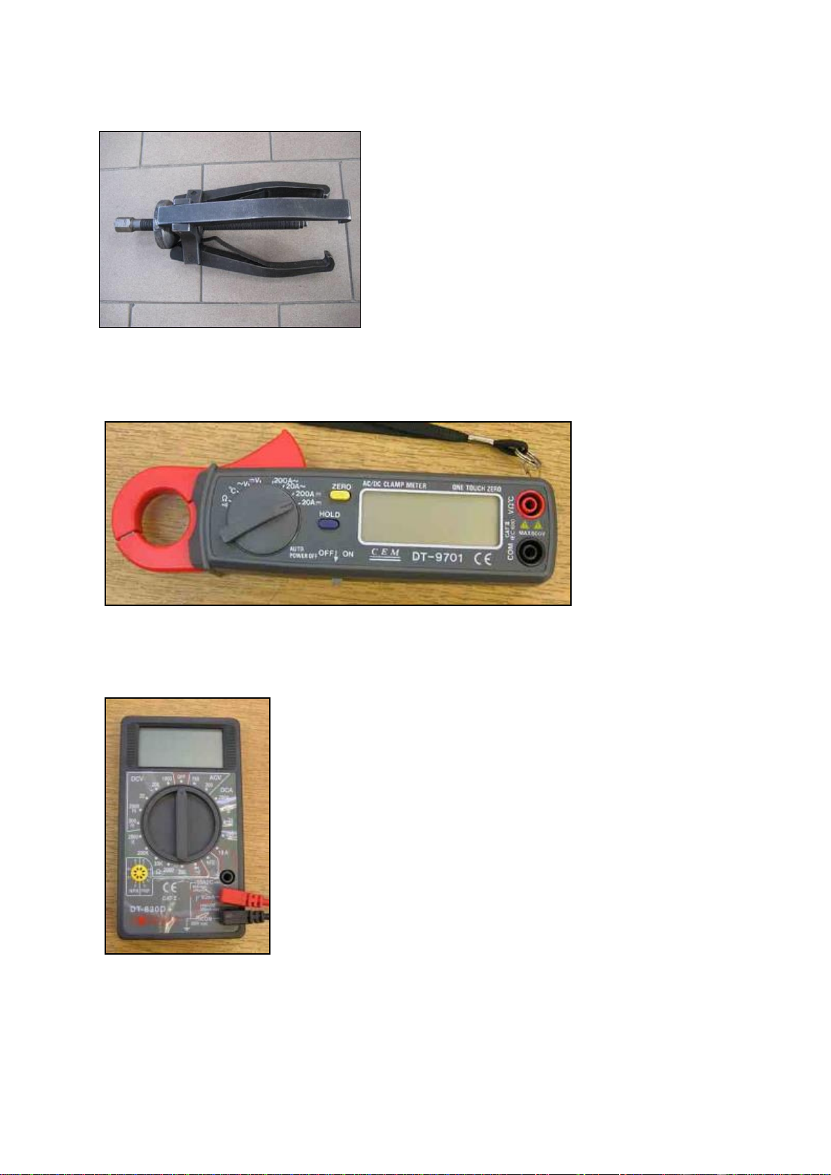
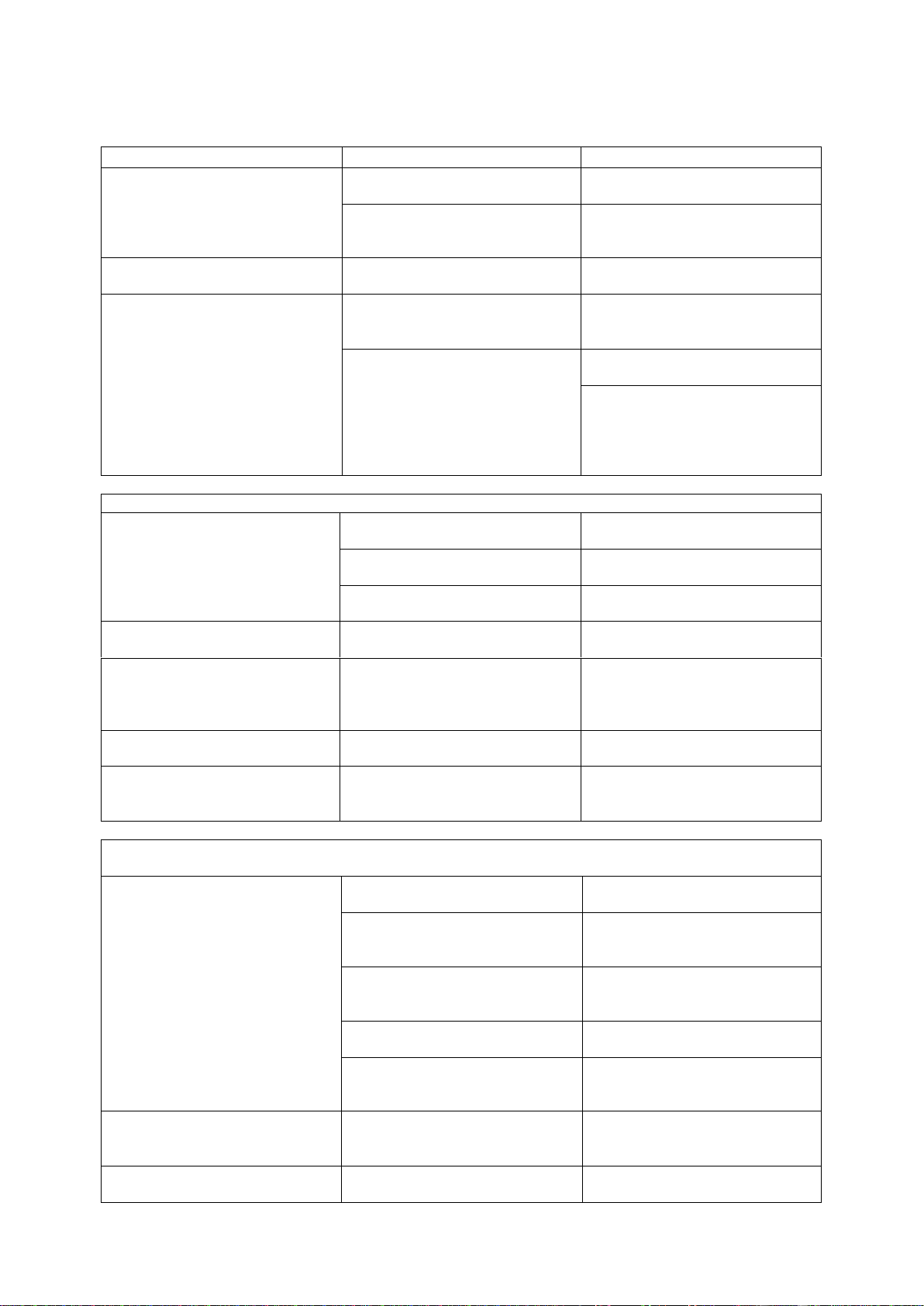
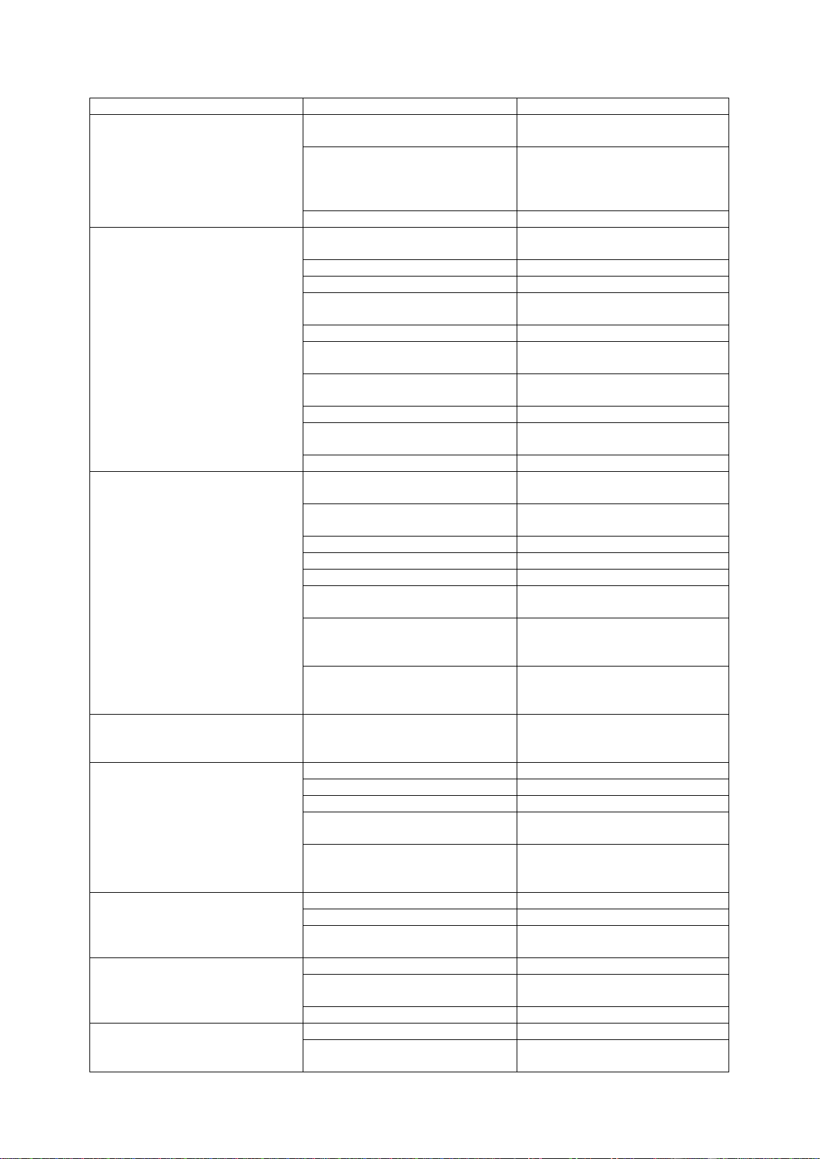
1 SPECIAL SERVICE TOOLS..........................................................................................................4
2 TROUBLESHOOTING ..................................................................................................................6
3 BASIC TECHNICAL SPECIFICATIONS.......................................................................................9
4 REGULAR MAINTENANCE OF SPIDER MINI .........................................................................10
4.1 DAILY OR EACH 8 mth......................................................................................................10
4.2 AFTER FIRST 5 HOURS.....................................................................................................13
4.3 AFTER 50 HOURS............................................................................................................... 13
4.4 AFTER 200 hours.................................................................................................................14
4.5 SEASONAL PERIOD .......................................................................................................... 16
5 ENGINE MAINTENANCE CHART .............................................................................................19
6 INSTRUCTION MANUAL SPIDER MINI ................................................................................... 20
6.1 Tilting of the mower for maintenance-service position.........................................................20
6.2 Replacement of engine oil and filter .....................................................................................21
6.3 Replacement of hydraulic oil and filter.................................................................................22
6.4 Replacement of hydraulic pump ........................................................................................... 24
6.5 Replacement of hydraulic motor...........................................................................................28
6.6 Replacement of the clutch, drive V-belt and engine pulley ..................................................33
6.7 Replacement of the blade hub and bearing ........................................................................... 37
6.8 Sharpening of the blade.........................................................................................................39
6.9 Replacement of the steering chain ........................................................................................40
6.10 Replacement of the steering servomotor............................................................................. 41
6.11 Replacement of the main drive chain..................................................................................43
6.12 Replacement of the wheel chain.......................................................................................... 46
6.13 Replacement of the wheel shaft, bearings and chain tensioners..........................................53
6.14 Replacement of the wheel suspension.................................................................................58
6.15 Wheel geometry alignment .................................................................................................62
6.16 Replacement of the alternator .............................................................................................66
6.17 Replacement of the drive servomotor .................................................................................68
6.18 Replacement of the brake solenoid .....................................................................................73
6.19 Replacement of the main harness........................................................................................75
6.20 Carburetor of the engine Briggs &Stratton Professional 950.............................................. 80
6.21 Modification of the engine brake Briggs & Stratton...........................................................81
6.22 Replacement of the engine Briggs & Stratton Professional 950 .........................................82
6.23 Hydraulic circuit .................................................................................................................87
6.24 Torque chart........................................................................................................................88
6.25 Lubricators .......................................................................................................................... 88
7 ELECTRICAL SYSTEM ...............................................................................................................89
7.1 Electrical component location............................................................................................... 89
7.2 Electric circuit diagram......................................................................................................... 90
7.3 Fuse box................................................................................................................................ 91
7.4 Current measurement table...................................................................................................92
7.5 Main switch –Emergency STOP..........................................................................................92
7.6 Horn ......................................................................................................................................93
7.7 Brake solenoid.......................................................................................................................93
7.8 Light for neutral position ......................................................................................................94
7.9 Battery ..................................................................................................................................94
7.10 Steering servomotor PAL ................................................................................................... 95
7.11 Drive servomotor NBB ......................................................................................................95
7.12 Alternator - charging...........................................................................................................96
7.13 Control unit NBB................................................................................................................97
Programming of the control unit..................................................................................................... 98

3/ 102 SM-8 Ev3/08072015
TECHNICAL SPECIFICATIONS
Parameter
Unit
Value
Length/Width
mm (inch)
910 x 1040 (36 x 41)
Height
mm (inch)
600 (23,6)
Mowing width
mm (inch)
560 (22)
Mowing blade height
mm (inch)
40 –90 (1,5 –3,5) - 6 levels
Weight
kg (pound)
125 kg (275)
Driving speed
km/h (mph)
0 –4 (2,5)
Mower deck
-
Single blade with a firm blade attached to a clutch flange
Blade clutch
-
Mechanical with a friction brake
Hydraulic pump
Hydro Gear PC
Hydraulic motor
-
Sauer Danfoss OMM20
Drive system
-
4 x 4
Wheels
inch
13 x 5,00 –6 with V-pattern
Battery
12 V, 18 Ah, gel
Fuel
-
Unleaded petrol / gasoline
Fuel tank capacity
litre (gallon)
4 (1)
Engine
Briggs&Stratton 950 Professional Series
Cylinder volume
cm3
223
Power output
HP/min-1
4,1 /3060
Torque
N.m/min-1
12,59 / 3060
Ignition
Electronic
Starting
Electric
Frequency range of the Remote
controller NBB for EU and USA
for Japan
MHz
433.100 - 434.750
429.250-429.7375 MHz

4/ 102 SM-8 Ev3/08072015
1 SPECIAL SERVICE TOOLS
Wooden blocks for lifting the mower ( 150x130x80) –4 pieces
Stright lath for wheel geometry adjustment (length 1100 mm)
Oil filter release jig

5/ 102 SM-8 Ev3/08072015
Wheel hub puller
Ampere meter CEM DT –9701
Voltmeter Ben electronic DT - 830 D+

6/ 102 SM-8 Ev3/08072015
2 TROUBLESHOOTING
Problem
Possible cause
Correction
No green light illuminates after RC
is turned on
No or empty batteries in the RC
Insert fully charged batteries into
the RC.
RC failure
Turn off the RC and turn it on
again. If restart does not help,
contact an authorized service.
Red light flashes after RC is turned
on
Empty RC batteries
Insert fully charged batteries into
the RC.
After pressing the confirmation /
horn button a connection between
the RC and the mower is not
established. The mower is
otherwise fully functional.
The RC does not belong to this
mower.
Check the RC number and Control
Unit number. They must be
identical. Use the correct RC.
Signal is interfered with by another
device working on the same
frequency.
Turn off the interfering device, get
closer to the mower.
Press and holed the antenna button
on the RC and at the same time
press the horn button to change the
RC channel. Then press the horn
button again.
The mower does not activate after turning on the main switch on the mower
Beacon does not flash (failure of
main electric power supply)
Battery is not connected properly or
is empty
Properly connect a fully charged
battery.
Disconnected cables of the mower
electric harness
Check cables and connectors.
Main fuse failure
Change the fuse for a new one with
the same value
Beacon flashes (electric power is
supplied)
Mower battery is not fully charged
Charge or replace mower battery
Connection between the RC and the
Control Unit was not confirmed
Repeatedly press the RC
confirmation button. Check the RC
functions. See the beginning of this
chapter.
Control Unit is not properly
connected
Check the LED light on the Control
Unit. It must flash.
Control unit is properly connected,
but the light on the Control Unit is
not flashing.
Control unit failure. Contact an
authorized service centre.
Mower cannot be started. Communication between RC and Control Unit is OK. Mower power supply is
OK. Beacon is flashing.
Neutral light is not illuminated
Communication between RC and
Control Unit was not confirmed.
Press confirmation / horn button on
the RC
Drive servomotor is not in the
neutral position.
Move drive joystick slightly
forward and backward until neutral
light illuminates.
Check if the drive servomotor lever
is not mechanically blocked (by
debris, sticks etc.)
Release the drive servo lever so
that it can freely move.
Light is damaged (does not affect
starting of the mower)
Change the LED neutral light
Servo lever does not respond to
joystick movement
Restart the mower and try again.
Otherwise contact authorized
service
Neutral light is illuminated
No relay clicking sound is audible
from the fuse box when start button
on the RC is pressed
Change the starter relay in the fuse
box.
Neutral light is illuminated.
Starter relay works correctly.
Engine brake is activated
Release the engine brake by
pressing the lever, which activates

7/ 102 SM-8 Ev3/08072015
starter and ignition.
Neutral light is illuminated.
Starter relay works correctly.
Engine brake is released
Disconnected cable between fuse
box and starter
Check cables and connectors
Defective switch of the engine
brake (under engine cover)
Check voltage before and behind
the engine brake switch. You
should read 12 V when start button
is pressed.
Defective engine starter
Replace the engine starter
Mower cannot be started.
Starter freely turns the engine.
Closed fuel cock or lack of fuel in
the fuel tank
Check the fuel cock and refuel
Clogged fuel filter
Change the fuel filter.
Low quality fuel
Change fuel
Disconnected or defective spark
plug
Check the spark plug and replace if
necessary
Broken ignition cable
Check the cable
Defective switch of the engine
brake
Change the switch.
Dirty air filter
Clean or change the air filter and
rough air filter
Clogged and dirty carburettor
Clean the carburettor
Blocked or non-functional
automatic engine choke.
Check the choke line, replace if
necessary.
Clogged engine exhaust.
Clean
Mower cannot be started.
Starter turns the engine with
difficulty.
Blocked mowing blade
Disengage blade clutch and select
maximum height of cut
Empty battery
Check battery voltage and recharge
or replace battery if necessary.
Lack of engine oil
Check and add engine oil
Worn starter pinion
Replace
Defective started
Replace
Blocked drive belt
Clean the belt space and make sure
it turns freely
Blocked hydraulic pump.
(possible repair should only be
performed by authorized service)
After releasing drive belt check if
the pump pulley freely turns.
Blocked alternator
After releasing drive belt check if
the alternator freely turns. Clean
the space around the alternator.
Drive servo lever does not react.
Connection between RC and CU is
OK. Mower can be started.
Loose lever between the
servomotor and the hydraulic pump
Check the tightness of nuts and
bolts of the lever mechanism
Mower drive does not work or is
insufficient
Open pump By-pass
Close the pump By-pass
Worn, broken or loose drive belt
Check the drive belt
Lack of oil in hydraulic system
Add oil in authorized service
Worn mechanical elements of the
hydraulic circuit
Change in authorized service
Overheated hydraulic oil
Let the mower cool down and clean
the space around the hydraulic
pump for better cooling
Mowing blade clutch slips
Dirty functional surfaces of clutch
Clean
Clutch worn out excessively
Replace worn components
Clutch damaged by hitting a firm
obstacle
Check the blade hub and replace if
necessary.
Clutch does not stop the blade
Dirty functional surfaces of clutch.
Clean
Block clutch disengagement
mechanism
Check and clean.
Clutch worn out excessively
Replace worn components
Clutch makes noise
Dirty functional surfaces of clutch.
Clean
Clutch loose on the crankshaft or
loose blade.
Tighten and glue fastening bolts of
clutch and blade

8/ 102 SM-8 Ev3/08072015
Worn clutch bearings
Check free turning of functional
components of the clutch. Replace
if necessary.
Mower vibrates when clutch
engaged.
Unbalanced or bent blade
Balance and sharpen blade, replace
if necessary
Damaged blade hub
Replace
Bent crankshaft
Contact authorized service
Insufficiently tightened blade
Glue and tighten blade bolts
Mower pivots around vertical axis
while driving
Unevenly inflated tyres
Check tyre pressure
Wrong wheel geometry
Check and adjust geometry
Bad mowing quality
Overgrown, wet or tall grass
Mow grass max. 3x higher than the
selected height of cut. Let the grass
dry before mowing.
Blunt or worn mowing blade
Sharpen or replace the blade
Low engine RPM
Check engine RPM in an
authorized service centre
High driving speed
Slow down
Clogged mower deck
Clean
Engine brake does not work when
EMERGENCY STOP button is
pressed
Dirty surfaces of the lever
mechanism
Clean and lubricate
Mechanically damaged brake
mechanism.
Check in an authorized service
centre.
Engine brake excessively worn
Replace in an authorized service
centre.

9/ 102 SM-8 Ev3/08072015
3 BASIC TECHNICAL SPECIFICATIONS

10 / 102 SM-8 Ev3/08072015
4 REGULAR MAINTENANCE OF SPIDER MINI
4.1 DAILY OR EACH 8 mth
a) Check leakage of engine and hydraulic oil
b) Check and add engine oil level, fill up to the
maximum mark on the dipstick
- see 6.2 Replacement of engine oil and filter
c) Check tires pressure 200 kPa / 2 bar / 30 PSI
Dipstick
max
min

11 / 102 SM-8 Ev3/08072015
d) Check tightening of steering and driving chains
- see 6.9 Replacement of the steering chain
- see 6.11 Replacement of the main drive chain
e) Check out electric and safety equipment
f) Check geometry and sharpening of the blade
- see 6.8 Sharpening of the blade
g) Check tightening of blade bolts
h) Retighten all bolts and nuts
ch) Clean the engine cooling system, exhaust cover, alternator, starter, hydraulic pump and controls
Blade bolts
Sharpening of the blade

12 / 102 SM-8 Ev3/08072015
d) Lubricate the sliding of the machine shown in the figure below
- Use a spray lubricant: Berner grease for chains

13 / 102 SM-8 Ev3/08072015
4.2 AFTER FIRST 5 HOURS
a) Change engine oil
- see 6.2 Replacement of engine oil and filter
4.3 AFTER 50 HOURS
a) Check tightening of V-belt
- see 6.6 Replacement of the clutch, drive V-belt and engine pulley
b) Check or recharge main gel battery
c) Retighten all bolts and nuts
d) Check and clean mechanical blade clutch
- Remove the cover of the mowing device and blow it with compressed air
- Check the wear on the clutch plates and brake, the brake must not touch the clutch plate with engaged blades
- see 6.6 Replacement of the clutch, drive V-belt and engine pulley
e) Change engine oil
- see 6.2 Replacement of engine oil and filter
f) Change engine oil filter
- see 6.2 Replacement of engine oil and filter

14 / 102 SM-8 Ev3/08072015
g) Check and add engine oil level, fill up to the maximum mark on the dipstick
h) Clean paper and rough air filters
4.4 AFTER 200 hours
a) Check or adjust wheel geometry
- see 6.15 Wheel geometry alignment
b) Adjust neutral position of driving system –SW SpiderMiniConfig - see Programming of the control unit
or use a special procedure (adjustment of the neutral position by steering joystick) - see 6.17 Replacement of
the drive servomotor

15 / 102 SM-8 Ev3/08072015
c) Change hydraulic oil and filter
- see 6.3 Replacement of hydraulic oil and filter
d) Check oil level of wheel suspension
- see 6.12 Replacement of the wheel chain
e) Check or replace drive V-belt
- see 6.6 Replacement of the clutch, drive V-belt and engine pulley
f) Check bearings of the clutch and blade hub
- see 6.6 Replacement of the clutch, drive V-belt and engine pulley

16 / 102 SM-8 Ev3/08072015
g) Replace paper and rough air filters
4.5 SEASONAL PERIOD
a) Visually check hydraulic hoses, fuel leading, wiring or eventually exchange
b) Adjust neutral position of driving system –SW SpiderMiniConfig- see Programming of the control unit or use
a special procedure (adjustment of the neutral position by steering joystick) - see 6.17 Replacement of the drive
servomotor
c) ) Change hydraulic oil and filter
- see 6.3 Replacement of hydraulic oil and filter

17 / 102 SM-8 Ev3/08072015
d) Check oil level inside the wheel suspension
- see 6.12 Replacement of the wheel chain
e) Check after-running limit of the blade
f) Check bearings of the clutch
- see 6.6 Replacement of the clutch, drive V-belt and engine pulley
g) Replace spark plugs
h) Replace fuel filter, breath filter and clean fuel tank

18 / 102 SM-8 Ev3/08072015
ch) Check and adjust valve clearance
Valve clearance:
Intake - 0,10 –0,20 mm
Exhaust - 0,10 –0,20 mm
Adjustment:
-Using a feeler gauge (A), adjust
rocker nut to obtain the clearance
-Hold rocker nut and tighten the
rockerball setscrew (B).
Piston must be in T.D.C. This prevents
the compression release from holding
the valves open

19 / 102 SM-8 Ev3/08072015
5 ENGINE MAINTENANCE CHART
First 5 Hours
Change oil
Every 8 Hours or Daily
Check engine oil level
Clean are around muffler and controls
Clean finger guard
Every 50 Hours or Annually
Clean air filter*
Clean pre-cleaner*
Change oil
Change oil filter
Check muffler and spark arrester
Every 200 Hours or Anually
Replace air filter*
Replace pre-cleaner*
Annually
Replace spark plug
Clean air cooling system*
Replace fuel filter
Check or adjust valve clearance
*In dusty conditions or when airborne debris is present, clean more often

20 / 102 SM-8 Ev3/08072015
6 INSTRUCTION MANUAL SPIDER MINI
6.1 Tilting of the mower for maintenance-service position
-Disconnect the battery and spark plug to prevent accidental starting of the machine and possible injury
-Turn the wheels across the direction of the tilt-wheel housings must be turned down
-Always tilt the mower exhaust up to prevent ingress of oil into the engine air intake and air filter
-Before starting work, make sure the mower is stable in this position, and that there is no possible rollover
-Secure it against a possible fall
-Leave the mower in this position only for the time required for maintenance
-Do not use cutting height adjustment in this position , it could cause an injury
Hydraulic tank
Exhaust
Wheel housing
Table of contents
Other Dvorak Lawn Mower manuals
Popular Lawn Mower manuals by other brands

Western Auto
Western Auto NOP7122A19 Operation and service instructions

MTD
MTD 121-838E000 owner's guide

McCulloch
McCulloch M3750SM instruction manual

Scag Power Equipment
Scag Power Equipment SW-13KA Technical manual

Stihl
Stihl FCS-KM instruction manual

Cub Cadet Commercial
Cub Cadet Commercial Z-Wing 48 Operator's and service manual