E.F. Johnson 5100 SERIES User manual

DIGITAL/ANALOG PORTABLE RADIO
OPERATING
MANUAL
5100 SERIES
PORTABLE RADIO
■APCO Project 25
– Conventional
– Trunked
■SMARTNET®/
SmartZone®
■Analog FM
Conventional
VHF
UHF
700/800 MHZ
Part No. 242-51xx-xxx
Part Number 002-5100-1006
December 2004
Supersedes: 002-5100-1005, 5/04

5100 SERIES PORTABLE
OPERATING MANUAL
■APCO PROJECT 25 CONVENTIONAL
■APCO PROJECT 25 TRUNKED
■SMARTNET®/SmartZone®
■ANALOG (FM) CONVENTIONAL
■VHF/UHF/800 MHz
Copyright© 2004 by the E.F. Johnson Company
The E.F. Johnson Company, which was founded in 1923, provides wireless communication
systems solutions for public safety, government, and commercial customers. The company
designs, manufactures, and markets conventional and trunked radio systems, mobile and
portable subscriber radios, repeaters, and Project 25 digital radio products. EFJohnson is a
wholly owned subsidiary of EFJ, Inc.
Viking Head/EFJohnson logo, PCConfigure™, and Call Guard®are trademarks of the E.F.
Johnson Company. SMARTNET®, SmartZone®, SecureNet™, Call Alert™, Enhanced Pri-
vate Conversation™, and Private Conversation II™are trademarks of Motorola, Inc. All other
company and/or product names used in this manual are trademarks and/or registered trade-
marks of their respective manufacturer. The IMBE™ voice coding technology embodied in
this product is protected by intellectual property rights including patent rights of Digital Voice
Systems, Inc.
LAND MOBILE PRODUCT WARRANTY - The manufacturer’s warranty statement for this
product is available from your product supplier or from E.F. Johnson Company, 1440
Corporate Drive, Irving, TX 75038-2401. Phone toll free 1-800-328-3911.
Information in this manual is subject to change without notice.
This manual covers 51xx firmware through Version 1.16/2.6/3.6/4.2 and PCConfigure software through Version 1.26.

3
TABLE OF CONTENTS
TABLE OF CONTENTS
SAFETY INFORMATION
Federal Communications Commission Regulations 6
Compliance with RF Exposure Standards. . . . . . . .6
RF Exposure Compliance and Control Guidelines
and Operating Instructions . . . . . . . . . . . . . . . . .7
Contact Information. . . . . . . . . . . . . . . . . . . . . . . . .7
Electromagnetic Interference. . . . . . . . . . . . . . . . . .7
Usage Compatibility . . . . . . . . . . . . . . . . . . . . . . . .7
Battery Disposal. . . . . . . . . . . . . . . . . . . . . . . . . . . .7
1 FEATURES
1.1 General Features . . . . . . . . . . . . . . . . . . . . . . . . . . .8
1.2 Conventional Features . . . . . . . . . . . . . . . . . . . . . . .8
1.3 SMARTNET/SmartZone Features . . . . . . . . . . . . .8
1.4 Project 25 Trunked Features . . . . . . . . . . . . . . . . . .9
2 CONTROLS AND DISPLAY
2.1 Front Panel Controls . . . . . . . . . . . . . . . . . . . . . . .10
2.2 Top Panel Controls . . . . . . . . . . . . . . . . . . . . . . . .11
2.3 Side Controls . . . . . . . . . . . . . . . . . . . . . . . . . . . . .11
2.4 Display. . . . . . . . . . . . . . . . . . . . . . . . . . . . . . . . . .12
3 GENERAL OPERATION
3.1 Turning Power On and Setting Volume . . . . . . . .13
Power Up . . . . . . . . . . . . . . . . . . . . . . . . . . . . . 13
Standard and Soft Power Down . . . . . . . . . . . . 13
Setting Volume Level. . . . . . . . . . . . . . . . . . . . 13
3.2 Power-Up Password. . . . . . . . . . . . . . . . . . . . . . . .13
General . . . . . . . . . . . . . . . . . . . . . . . . . . . . . . . 13
Password Features With Later Models. . . . . . . 14
Password Features with Early Unrevised
Models . . . . . . . . . . . . . . . . . . . . . . . . . . . . . 14
3.3 Zone and Channel Select . . . . . . . . . . . . . . . . . . . .14
3.4 Low Battery Indication . . . . . . . . . . . . . . . . . . . . .16
General . . . . . . . . . . . . . . . . . . . . . . . . . . . . . . . 16
Battery Charging. . . . . . . . . . . . . . . . . . . . . . . . 16
3.5 Backlight . . . . . . . . . . . . . . . . . . . . . . . . . . . . . . . .16
3.6 Keypad Lock . . . . . . . . . . . . . . . . . . . . . . . . . . . . .16
3.7 Setting Squelch . . . . . . . . . . . . . . . . . . . . . . . . . . .17
3.8 Transmit Disable. . . . . . . . . . . . . . . . . . . . . . 17
3.9 Radio Operating Modes. . . . . . . . . . . . . . . . . . . . .17
General. . . . . . . . . . . . . . . . . . . . . . . . . . . . 17
Conventional Mode. . . . . . . . . . . . . . . . . . . . . . 17
SMARTNET/SmartZone Mode . . . . . . . . . . . . 18
P25 Trunked Mode . . . . . . . . . . . . . . . . . . . . . . 18
Systems, Channels, and Zones . . . . . . . . . . . . . 18
4 RADIO-WIDE FEATURES
4.1 Option Switches . . . . . . . . . . . . . . . . . . . . . . . . . . 20
4.2 Menu Mode. . . . . . . . . . . . . . . . . . . . . . . . . . . . . . 20
4.3 Time-Out Timer . . . . . . . . . . . . . . . . . . . . . . . . . . 20
4.4 Home Zone/Channel Select . . . . . . . . . . . . . . . . . 22
4.5 Power Output Select. . . . . . . . . . . . . . . . . . . . . . . 22
4.6 Alert Tone Select . . . . . . . . . . . . . . . . . . . . . . . . . 22
4.7 Surveillance Mode . . . . . . . . . . . . . . . . . . . . . . . . 22
4.8 Scanning . . . . . . . . . . . . . . . . . . . . . . . . . . . . . . . . 23
Introduction . . . . . . . . . . . . . . . . . . . . . . . . . . . . 23
Priority Scanning . . . . . . . . . . . . . . . . . . . . . . . . 23
Radio Wide Scanning . . . . . . . . . . . . . . . . . . . . 23
Scan Hold Time. . . . . . . . . . . . . . . . . . . . . . . . . 23
Transmitting in the Scan Mode . . . . . . . . . . . . . 24
Nuisance Channel Add/Delete. . . . . . . . . . . . . . 24
4.9 Scan Lists . . . . . . . . . . . . . . . . . . . . . . . . . . . . . . . 24
Priority Scan Lists . . . . . . . . . . . . . . . . . . . . . . . 24
Radio Wide Scan Lists. . . . . . . . . . . . . . . . . . . . 26
5 CONVENTIONAL MODE FEATURES
5.1 Introduction . . . . . . . . . . . . . . . . . . . . . . . . . . . . . 27
5.2 Monitoring Before Transmitting . . . . . . . . . . . . . 27
5.3 Monitor Mode. . . . . . . . . . . . . . . . . . . . . . . . . . . . 27
5.4 Busy Channel Lockout . . . . . . . . . . . . . . . . . . . . . 27
5.5 Call Guard Squelch. . . . . . . . . . . . . . . . . . . . . . . . 28
Introduction . . . . . . . . . . . . . . . . . . . . . . . . . . . . 28
Call Guard Squelch Enable/Disable . . . . . . . . . 28
Tone Call Guard Squelch. . . . . . . . . . . . . . . . . . 28
Digital Call Guard Squelch . . . . . . . . . . . . . . . . 28
Selective Sq Code Select (CTCSS/DCS/NAC). 29
5.6 Penalty Timer . . . . . . . . . . . . . . . . . . . . . . . . . . . . 29
5.7 Conversation Timer . . . . . . . . . . . . . . . . . . . . . . . 29
5.8 Repeater Talk-Around . . . . . . . . . . . . . . . . . . . . . 30
5.9 Displaying Transmit/Receive Frequency . . . . . . . 30
5.10 Emergency Alarm and Call . . . . . . . . . . . . . . . . . 30
Introduction . . . . . . . . . . . . . . . . . . . . . . . . . . . . 30
Emergency Alarms . . . . . . . . . . . . . . . . . . . . . . 30
Emergency Calls . . . . . . . . . . . . . . . . . . . . . . . . 31
Emergency Man-Down Feature. . . . . . . . . . . . . 31
5.11 Conventional Mode Scanning . . . . . . . . . . . . . . . 32
General. . . . . . . . . . . . . . . . . . . . . . . . . . . . . . . . 32
Transmitting in Scan Mode . . . . . . . . . . . . . . . . 32
Priority Channel Sampling . . . . . . . . . . . . . . . . 32
5.12 Standard Conventional Calls . . . . . . . . . . . . . . . . 33
5.13 DTMF/ANI Signaling. . . . . . . . . . . . . . . . . . . . . . 33
5.14 Single Tone Encoder . . . . . . . . . . . . . . . . . . . . . . 34
5.15 MDC1200 Compatibility . . . . . . . . . . . . . . . . . . . 34
5.16 Clone Mode . . . . . . . . . . . . . . . . . . . . . . . . . . . . . 34
General. . . . . . . . . . . . . . . . . . . . . . . . . . . . . . . . 34

TABLE OF CONTENTS
4
Wireless Cloning. . . . . . . . . . . . . . . . . . . . . . . . 34
Cloning Procedure . . . . . . . . . . . . . . . . . . . . . . 34
5.17 Project 25 Mode Features . . . . . . . . . . . . . . . . . . .35
Unit ID Code. . . . . . . . . . . . . . . . . . . . . . . . . . . 35
Group ID Code . . . . . . . . . . . . . . . . . . . . . . . . . 35
Network Access Code. . . . . . . . . . . . . . . . . . . . 35
P25 Group Calls . . . . . . . . . . . . . . . . . . . . . . . . 35
P25 Unit Calls. . . . . . . . . . . . . . . . . . . . . . . . . . 36
P25 Conventional Telephone Calls. . . . . . . . . . 36
Call Alert. . . . . . . . . . . . . . . . . . . . . . . . . . . . . . 37
Messaging. . . . . . . . . . . . . . . . . . . . . . . . . . . . . 38
Status Messaging . . . . . . . . . . . . . . . . . . . . . . . 38
P25 Packet Data . . . . . . . . . . . . . . . . . . . . . . . . 39
5.18 Keypad Programming . . . . . . . . . . . . . . . . . . . . . .39
Introduction. . . . . . . . . . . . . . . . . . . . . . . . . . . . 39
Menu Description . . . . . . . . . . . . . . . . . . . . . . . 39
Zone Password . . . . . . . . . . . . . . . . . . . . . . . . . 40
Zone Change Parameter . . . . . . . . . . . . . . . . . . 40
Channel Change Parameter. . . . . . . . . . . . . . . . 40
System Parameters . . . . . . . . . . . . . . . . . . . . . . 40
Channel Parameters . . . . . . . . . . . . . . . . . . . . . 40
6 SMARTNET/SMARTZONE/P25
TRUNKED FEATURES
6.1 Introduction . . . . . . . . . . . . . . . . . . . . . . . . . . . . . .43
6.2 Analog and Digital Operation . . . . . . . . . . . . . . . .43
6.3 Viewing Unit ID . . . . . . . . . . . . . . . . . . . . . . . . . .43
6.4 Standard Group Calls. . . . . . . . . . . . . . . . . . . . . . .43
Introduction. . . . . . . . . . . . . . . . . . . . . . . . . . . . 43
Placing a Standard Group Call . . . . . . . . . . . . . 43
Receiving a Standard Group Call . . . . . . . . . . . 43
6.5 Private (Unit-To-Unit) Calls . . . . . . . . . . . . . . . . .44
General . . . . . . . . . . . . . . . . . . . . . . . . . . . . . . . 44
Placing an Enhanced Private Conversation Call 44
Placing a Standard Private Conversation Call . 45
Receiving a Private Call (All Types) . . . . . . . . 46
6.6 Telephone Calls . . . . . . . . . . . . . . . . . . . . . . . . . . .46
General . . . . . . . . . . . . . . . . . . . . . . . . . . . . . . . 46
Placing a Telephone Call . . . . . . . . . . . . . . . . . 46
Answering a Telephone Call. . . . . . . . . . . . . . . 47
6.7 Call Alert . . . . . . . . . . . . . . . . . . . . . . . . . . . . . . .47
General . . . . . . . . . . . . . . . . . . . . . . . . . . . . . . . 47
Answering a Page . . . . . . . . . . . . . . . . . . . . . . . 47
Initiating a Page . . . . . . . . . . . . . . . . . . . . . . . . 48
6.8 Messaging . . . . . . . . . . . . . . . . . . . . . . . . . . . . . . .48
6.9 Sending Status Conditions. . . . . . . . . . . . . . . . . . .48
6.10 Emergency Alarm and Call . . . . . . . . . . . . . . . . . .48
Introduction. . . . . . . . . . . . . . . . . . . . . . . . . . . . 48
Emergency Alarms . . . . . . . . . . . . . . . . . . . . . . 49
Emergency Calls. . . . . . . . . . . . . . . . . . . . . . . . 49
Emergency Man-Down Feature . . . . . . . . . . . . 50
6.11 Failsoft Operation . . . . . . . . . . . . . . . . . . . . . . . . .50
6.12 SMARTNET/Smartzone/P25 Trunked Scanning
Features. . . . . . . . . . . . . . . . . . . . . . . . . . . . . . . . . 50
General. . . . . . . . . . . . . . . . . . . . . . . . . . . . . . . . 50
Priority Talk Group Sampling . . . . . . . . . . . . . . 50
6.13 Dynamic Regrouping . . . . . . . . . . . . . . . . . . . . . . 51
6.14 SmartZone and P25 Trunked Unique Features. . . 51
Introduction . . . . . . . . . . . . . . . . . . . . . . . . . . . . 51
Busy Override . . . . . . . . . . . . . . . . . . . . . . . . . . 51
Site Trunking. . . . . . . . . . . . . . . . . . . . . . . . . . . 51
Determining Current Site and Searching For
New Site . . . . . . . . . . . . . . . . . . . . . . . . . . . . 52
Locking/Unlocking a Site . . . . . . . . . . . . . . . . . 52
ZoneFail Site Lock . . . . . . . . . . . . . . . . . . . . . . 52
P25 Wide Area Scan . . . . . . . . . . . . . . . . . . . . . 52
7 MISCELLANEOUS
7.1 Supervisory Tones . . . . . . . . . . . . . . . . . . . . . . . . 54
7.2 Error Messages. . . . . . . . . . . . . . . . . . . . . . . . . . . 55
7.3 System Operator Programming . . . . . . . . . . . . . . 56
7.4 Speaking Into Microphone . . . . . . . . . . . . . . . . . . 57
7.5 Operation At Extended Range . . . . . . . . . . . . . . . 57
7.6 Licensing . . . . . . . . . . . . . . . . . . . . . . . . . . . . . . . 57
7.7 Radio Service . . . . . . . . . . . . . . . . . . . . . . . . . . . . 57
8 DETERMINING AVAILABLE OPTIONS
8.1 General . . . . . . . . . . . . . . . . . . . . . . . . . . . . . . . . . 58
8.2 Upgrading A Radio With New Options . . . . . . . . 58
8.3 Using PCConfigure To Determine Options . . . . . 58
9 51xx FIRMWARE VERSIONS
9.1 General . . . . . . . . . . . . . . . . . . . . . . . . . . . . . . . . . 60
9.2 Firmware Version Used . . . . . . . . . . . . . . . . . . . . 60
9.3 Programming Software Required. . . . . . . . . . . . . 61
10 PASSWORD DESCRIPTION
10.1 New Password Enhancements . . . . . . . . . . . . . . . 61
Introduction . . . . . . . . . . . . . . . . . . . . . . . . . . . . 61
Software Versions Required . . . . . . . . . . . . . . . 61
Availability With Earlier Versions . . . . . . . . . . 61
10.2 Programming Passwords . . . . . . . . . . . . . . . . . . . 61
General. . . . . . . . . . . . . . . . . . . . . . . . . . . . . . . . 61
Lost Passwords . . . . . . . . . . . . . . . . . . . . . . . . . 61
Changing Password . . . . . . . . . . . . . . . . . . . . . . 62
Password Entry Procedure. . . . . . . . . . . . . . . . . 62
10.3 Password Description. . . . . . . . . . . . . . . . . . . . . . 62
User (Power-On) Passwords . . . . . . . . . . . . . . . 62
Download/Upload Passwords . . . . . . . . . . . . . . 62
Master Password . . . . . . . . . . . . . . . . . . . . . . . . 62
10.4 Zone Password . . . . . . . . . . . . . . . . . . . . . . . . . . . 62

TABLE OF CONTENTS
5
11 SECURE COMMUNICATION
(ENCRYPTION)
11.1 General . . . . . . . . . . . . . . . . . . . . . . . . . . . . . . . . .63
Introduction. . . . . . . . . . . . . . . . . . . . . . . . . . . . 63
Encryption Algorithms . . . . . . . . . . . . . . . . . . . 63
Encryption Available With Various Channel
Types . . . . . . . . . . . . . . . . . . . . . . . . . . . . . . 63
5100 Encryption Capabilities . . . . . . . . . . . . . . 63
FIPS and Non-FIPS Modes. . . . . . . . . . . . . . . . 64
11.2 Encryption Keys . . . . . . . . . . . . . . . . . . . . . . . . . .64
Introduction. . . . . . . . . . . . . . . . . . . . . . . . . . . . 64
Key and Algorithm IDs. . . . . . . . . . . . . . . . . . . 64
PID/SLN Key Management Modes . . . . . . . . . 64
Maintaining Keys in Memory. . . . . . . . . . . . . . 65
Encryption Key Select . . . . . . . . . . . . . . . . . . . 65
Encryption Key Erase. . . . . . . . . . . . . . . . . . . . 65
Encryption Icon Operation . . . . . . . . . . . . . . . . 65
11.3 Clear/Secure Strapping . . . . . . . . . . . . . . . . . . . . .66
Transmit Mode Options . . . . . . . . . . . . . . . . . . 66
Receive Mode Options . . . . . . . . . . . . . . . . . . . 66
Talk Group Encryption Override . . . . . . . . . . . 66
11.4 OTAR (Over-The-Air Rekeying) . . . . . . . . . . . . .67
Introduction. . . . . . . . . . . . . . . . . . . . . . . . . . . . 67
Encryption Key Types. . . . . . . . . . . . . . . . . . . . 67
Keysets. . . . . . . . . . . . . . . . . . . . . . . . . . . . . . . . 67
Crypto Groups . . . . . . . . . . . . . . . . . . . . . . . . . . 67
Key Management Facility . . . . . . . . . . . . . . . . . 68
Message Number Period (MNP) . . . . . . . . . . . . 68
Definitions . . . . . . . . . . . . . . . . . . . . . . . . . . . . . 68
11.5 Radio Setup For Encryption . . . . . . . . . . . . . . . . . 70
General Encryption Setup . . . . . . . . . . . . . . . . . 70
Additional Setup For OTAR . . . . . . . . . . . . . . . 71
11.6 Radio OTAR Capabilities. . . . . . . . . . . . . . . . . . . 72
SEM 5100/53xx, Standard 51xx . . . . . . . . . . . . 72
UCM Equipped 5100. . . . . . . . . . . . . . . . . . . . . 72
OTAR Option Switches. . . . . . . . . . . . . . . . . . . 72
INDEX . . . . . . . . . . . . . . . . . . . . . . . . . . . . . . . . 74

6
SAFETY INFORMATION
RF ENERGY EXPOSURE AWARENESS AND CONTROL INFORMATION, AND
OPERATIONAL INSTRUCTIONS FOR FCC OCCUPATIONAL USE REQUIREMENTS
Before Using Your Portable Two-Way Radio, Read
This Important RF Energy Awareness And Control
Information And Operational Instructions To
Ensure Compliance With The FCC’s RF Exposure
Guidelines.
NOTICE: This radio is intended for use in occupa-
tional/controlled conditions where users have full
knowledge of their exposure and can exercise control
over their exposure to meet FCC limits. This radio
device is NOT authorized for general population,
consumer, or any other use.
This two-way radio uses electromagnetic energy
in the radio frequency (RF) spectrum to provide
communications between two or more users over a
distance. It uses radio frequency (RF) energy or radio
waves to send and receive calls. RF energy is one form
of electromagnetic energy. Other forms include, but
are not limited to, electric power, sunlight and x-rays.
RF energy, however, should not be confused with
these other forms of electromagnetic energy, which
when used improperly can cause biological damage.
Very high levels of x-rays, for example, can damage
tissues and genetic material.
Experts in science, engineering, medicine, health
and industry work with organizations to develop stan-
dards for exposure to RF energy. These standards
provide recommended levels of RF exposure for both
workers and the general public. These recommended
RF exposure levels include substantial margins of
protection. All two-way radios marketed in North
America are designed, manufactured and tested to
ensure they meet government established RF expo-
sure levels. In addition, manufacturers also recom-
mend specific operating instructions to users of two-
way radios. These instructions are important because
they inform users about RF energy exposure and
provide simple procedures on how to control it. Please
refer to the following web sites for more information
on what RF energy exposure is and how to control
your exposure to assure compliance with established
RF exposure limits.
•http://www.fcc.gov/oet/rfsafety/rf-faqs.html
•http://www.osha.gov/SLTC/radiofrequencyradia-
tion/index.html
FEDERAL COMMUNICATIONS COMMISSION
REGULATIONS
The FCC rules require manufacturers to comply
with the FCC RF energy exposure limits for portable
two-way radios before they can be marketed in the U.S.
When two-way radios are used as a consequence of
employment, the FCC requires users to be fully aware of
and able to control their exposure to meet occupational
requirements. Exposure awareness can be facilitated by
the use of a product label directing users to specific user
awareness information. Your EFJohnson two-way radio
has a RF exposure product label. Also, your EFJohnson
user manual, or product manual, or separate safety
booklet includes information and operating instructions
required to control your RF exposure and to satisfy
compliance requirements.
COMPLIANCE WITH RF EXPOSURE
STANDARDS
Your EFJohnson two-way radio is designed and
tested to comply with a number of national and interna-
tional standards and guidelines (listed below) for human
exposure to radio frequency electromagnetic energy. This
radio complies with the IEEE and ICNIRP exposure
limits for occupational/controlled RF exposure environ-
ment at operating duty factors of up to 50% transmitting
and is authorized by the FCC for occupational use only.
In terms of measuring RF energy for compliance with the
FCC exposure guidelines, your radio radiates measurable
RF energy only while it is transmitting (during talking),
not when it is receiving (listening) or in standby mode.
NOTE: The approved batteries supplied with this radio
are rated for a 5-5-90 duty factor (5% talk-5% listen -
90% standby), even though this radio complies with the
FCC occupational RF exposure limits and may operate
at duty factors of up to 50% talk.
Your EFJohnson two-way radio complies with the
following RF energy exposure standards and guidelines:
•United States Federal Communications Commission,
Code of Federal Regulations; 47 CFR §§ 1.1307,
1.1310, 2.1091 and 2.1093
•American National Standards Institute (ANSI) / Insti-
tute of Electrical and Electronic Engineers (IEEE)
C95. 1-1992

SAFETY INFORMATION
7
•Institute of Electrical and Electronic Engineers (IEEE)
C95.1-1999 Edition
RF EXPOSURE COMPLIANCE AND CONTROL
GUIDELINES AND OPERATING INSTRUCTIONS
To control your exposure and ensure compliance
with the occupational/controlled environment exposure
limits, always adhere to the following procedures.
Guidelines:
•Do not remove the RF Exposure Label from the
device.
•User awareness instructions should accompany the
device when it is transferred to other users.
•Do not use this device if the operational requirements
described herein are not met.
Operating Instructions:
•Transmit no more than the rated duty factor of 50% of
the time. To transmit (talk), push the Push-To-Talk
(PTT) button. To receive calls, release the PTT button.
Transmitting 50% of the time, or less, is important
because this radio generates measurable RF energy
exposure only when transmitting (in terms of
measuring for standards compliance).
•Hold the radio in a vertical position in front of face
with the microphone (and the other parts of the radio,
including the antenna) at least one inch (2.5 cm) away
from the nose. Keeping the radio at the proper distance
is important because RF exposures decrease with
distance from the antenna. The antenna should be kept
away from eyes.
•When worn on the body, always place the radio in an
EFJohnson approved clip, holder, holster, case, or
body harness for this product. Using approved body-
worn accessories is important because the use of
EFJohnson or other manufacturer’s non-approved
accessories may result in exposure levels which
exceed the FCC’s occupational/controlled environ-
ment RF exposure limits.
•If you are not using a body-worn accessory and are not
using the radio in the intended use position in front of
the face, then ensure the antenna and the radio are kept
at least one inch (2.5 cm) from the body when trans-
mitting. Keeping the radio at the proper distance is
important because RF exposures decrease with
increasing distance from the antenna.
•Use only EFJohnson approved supplied or replace-
ment antennas, batteries, and accessories. Use of non-
EFJohnson approved antennas, batteries, and accesso-
ries may exceed the FCC RF exposure guidelines.
•For a list of EFJohnson approved accessories, see the
service manual or marketing accessory lists or contact
the E.F. Johnson Company
CONTACT INFORMATION
Toll-Free: 1-800-328-3911
FAX: 972-818-0639
E-Mail: customerservice@efjohnson.com. You can also
e-mail a person directly if you know their first initial/last
name (example: jsmith@efjohnson.com).
You may also contact the Customer Service Depart-
ment by mail. Please include all information that may be
helpful in solving your problem. The mailing address is
as follows:
E.F. Johnson Company
Customer Service Department
1440 Corporate Drive
Irving, TX 75038-2401
ELECTROMAGNETIC INTERFERENCE
This device complies with Part 15 of the FCC rules.
Operation is subject to the condition that this device does
not cause harmful interference. In addition, changes or
modification to this equipment not expressly approved
by the E.F. Johnson Company could void the user’s
authority to operate this equipment (FCC Rules, 47CFR
Part 15.19).
USAGE COMPATIBILITY
DO NOT operate it in areas that are sensitive to RF
energy such as aircraft, hospitals, blasting sites, and fuel
storage sites. Areas with potentially flammable atmo-
spheres are usually, but not always, clearly posted. These
may include gas stations, fuel and chemical storage and
transfer stations, below deck on boats, and areas where
the air contains flammable chemicals or particles such as
grain dust or metal powders.
BATTERY DISPOSAL
Dispose of the nickel metal-hydride (NiMH) battery
used by this radio in accordance with local regulations.
DO NOT dispose of it in fire because it can explode.
Also, do not short the terminals because it may become
very hot.

8
FEATURES
SECTION 1 FEATURES
NOTE: The availability of many of the following
features is controlled by factory coding of your radio,
installed options, firmware version, and field
programming. Refer to Sections 8 and 9 for more
information.
1.1 GENERAL FEATURES
•The following operating modes are programmable:
– Conventional analog
– Conventional APCO Project 25 (digital)
– Trunked APCO Project 25 (digital)
– SMARTNET™/SmartZone®trunked (analog
or digital)
•Up to 32 zones with 16 channels each (512 channels
total) are standard.
•Large graphic display with backlight
•16-position channel select switch
•3-position rotary option switch
•Up to 9 (limited keypad) or 21 (DTMF keypad)
programmable option switches
•Each option button programmable with a different
function for each operating mode (Conventional,
SMARTNET/SmartZone, Trunked P25)
•Menu mode
•AES 256-bit FIPS 140-2 approved encryption
available on P25/digital channels
•DES/DES-XL64-bitencryptionavailableonanalog
channels, DES-OFB on digital channels (see
Section 11).
•Emergency calls for high priority system access
•Priority(standard) and Radio Widescanmodeswith
user programmable scan lists
•User selectable high and low power output
•Surveillance mode
•Time-out timer
•Keypad lock to prevent accidental key presses
•Power up password to prevent unauthorized use.
•Programmable and user adjustable tone volume
•Programmable minimum volume level
•Soft power down to prevent accidental power off
•Operates on both wide and narrow band channels
1.2 CONVENTIONAL FEATURES
•Up to 512 channels or talk groups programmable
•Repeater talk-around
•Carrier or Call Guard®(CTCSS/DCS) controlled
squelch on analog channels, NAC and talk group
IDs on P25 channels.
•Normal/selective squelch selectable by option
switch or menu
•Monitor mode selectable by option switch or menu
•Time out timer penalty and conversation timers
•Dual priority channel sampling when scanning
(analog and digital channels)
•Busy channel lockout (transmit disable on busy)
•Unit calls on P25 channels
•Telephone calls on P25 channels with overdialing
(firmware 1.16/2.6/3.6 or later).
•Cloning capability using a cable or wireless connec-
tion (some versions only, see Section 5.16)
•Emergency alarms and calls to alert a dispatcher of
an emergency condition (analog emergency avail-
able only with firmware 1.8.0/2.0/3.0 or later).
•Single tone encoder controllable by user on analog
channels
•ANI (Automatic Number Identification) on analog
channels
•MDC1200 ANI and Emergency Alert support
(models with firmware 4.x only).
•Call Alert™ on P25 channels (send and receive
pages) with firmware 1.8.0/2.0/3.0 or later.
•Predefined messages (up to 16) can be sent to a
dispatcher (P25 mode with firmware 1.8.0/2.0/3.0
or later only)
•Predefined status conditions (up to 8) can be sent to
a dispatcher (P25 mode with firmware 1.8.0/2.0/3.0
or later only)
•OTAR (Over-The-Air-Rekeying) compatible (P25
channels with firmware 1.5.0/2.0/3.0 or later).
•Keypad programming with password access
(Federal Government users only)
1.3 SMARTNET/SMARTZONE FEATURES
•Up to 512 talk groups programmable (channels
select talk groups)
•Group, Enhanced Private Conversation™, standard
Private Conversation, and Telephone calls
•Emergency alarms to alert a dispatcher of
emergency conditions
•Emergency calls for high priority system access

FEATURES
9
•Failsoft operation on a predefined conventional
channel if trunked system fails
•Priority group calls detected while listening to other
group calls when scanning
•Call Alert™ (send and receive pages)
•Predefined messages (up to 16) can be sent to a
dispatcher
•Predefined status conditions (up to 8) can be sent to
a dispatcher
•Dynamic regrouping (dispatcher can automatically
gather users on a channel to receive a message)
•Roaming (SmartZone only)
1.4 PROJECT 25 TRUNKED FEATURES
•Up to 512 talk groups programmable (channels
select talk groups)
•Group and Unit Calls
•Telephone calls with overdialing (with firmware
1.16/2.6/3.6 or later)
•Emergency alarms to alert a dispatcher of
emergency conditions
•Emergency calls for high priority system access
•Failsoft operation on a predefined conventional
channel if trunked system fails
•Priority group calls detected while listening to other
group calls when scanning
•Call Alert™ (send and receive pages)
•Predefined status conditions (up to 8) can be sent to
a dispatcher
•Dynamic regrouping (dispatcher can automatically
gather users on a channel to receive a message)
•Roaming
10
CONTROLS AND DISPLAY
SECTION 2 CONTROLS AND DISPLAY
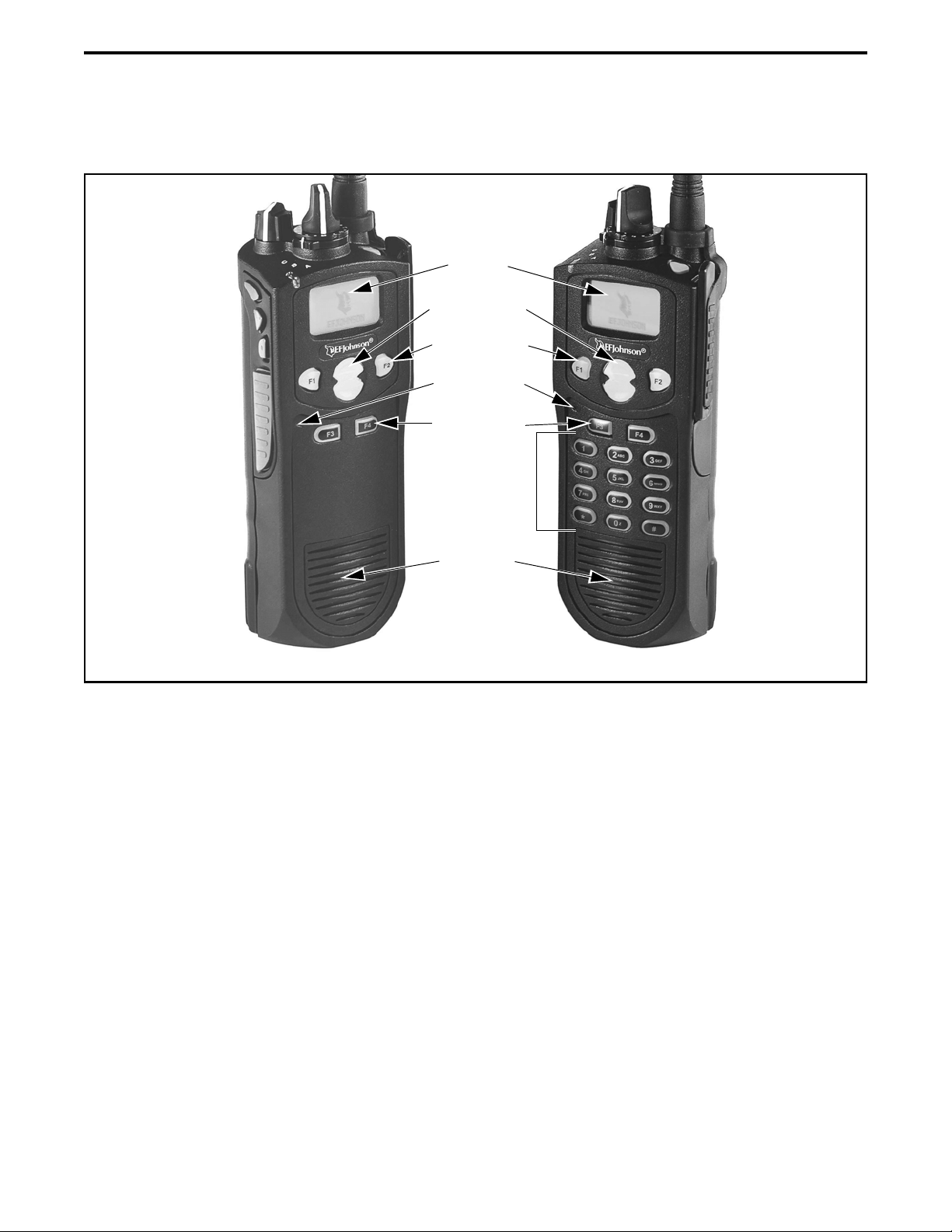
Figure 2-1 Front Panel Controls
Speaker
Display
DTMF Keypad
Option Keys
Microphone
DTMF Keypad Model
Limited Keypad Model
Up/Down Sw
Menu/Option
Keys
F1 = Exit
In Various Modes:
F2 = Select/Menu
Enable
2.1 FRONT PANEL CONTROLS
NOTE: The location of these controls is shown in
Figure 2-1.
Microphone - The microphone is located behind the
small opening shown in Figure 2-1. For best results,
hold the radio 2-3 inches from you mouth and speak at
a normal conversational level. Do not shout since it
distorts your voice and does not increase range.
Display - This is a graphical LCD (Liquid Crystal
Display). The display backlight can be programmed to
turn on when any key is pressed or when the Backlight
option switch is pressed or menu parameter selected
(see Section 3.5).
Up/Down Switch - Selects zones when multiple zones
are programmed (see Section 3.3). Pressing the upper
part of the switch selects the next higher number and
pressing the lower part selects the next lower number.
This control also provides up/down select in the menu
mode and in other modes when up/down select is
required.
F1 - In menu mode (see Section 4.2), functions as a
step back and exit switch. If menu mode is not used, it
is a programmable option switch.
F2 - Selects the menu mode when that mode is
enabled by programming. Also functions as an Enter
or Select switch in the menu and other modes. If menu
mode is not used, it is a programmable option switch.
F3, F4 - Programmable option switches.

CONTROLS AND DISPLAY
11
DTMF Keypad - The full keypad DTMF models
include the 12 keys required to dial telephone and unit
ID numbers.
Speaker - The radio speaker is located near the
bottom of the front panel. When a speaker/microphone
is used, it is automatically detected when the Opt Sel 1
line of the accessory connector is pulled low. The logic
then automatically disables the internal speaker.
Figure 2-2 Top Panel Controls
2.2 TOP PANEL CONTROLS
Multi-Function Indicator - Indicates the following
conditions:
Steady Red - Transmitter keyed.
Flashing Red - Low battery in receive mode.
Steady Green - Carrier detected in receive mode.
NOTE: This indicator is disabled if the Surveillance
mode is programmed (see Section 4.7).
On-Off/Volume - Turning the knob clockwise turns
power on and sets the volume level. Turning it coun-
terclockwise to the detent turns power off. The
minimum volume level can be set by programming.
Soft power down can be programmed as described in
Section 3.1.2, and the volume control can be disabled
as described in Section 3.1.3.
Channel Switch - This 16-position switch selects up
to 16 channels in the current zone. Additional zones
can be programmed to allow up to 512 channels to be
selected by this switch. This control can be disabled as
described in Section 3.3.
Rotary Option Switch - This is a three-position
switch that can be programmed to control various
options. The “A” position is “on” and the “B” and “C”
positions are “off” (see Section 4.1). When this switch
is programmed to select zones, “A” selects Zone 1,
“B” Zone 2, and “C” Zone 3 if applicable (available
only with firmware 1.7.0 or later).
Antenna Connector - Connection point for the
antenna. Make sure the antenna is tight before using
the radio.
Emergency Switch - This switch or some other option
switch can be programmed as an Emergency switch to
alert a dispatcher of an emergency condition. Refer to
Sections 5.10 and 6.10 for more information. This
switch can also be programmed for other functions.
2.3 SIDE CONTROLS
Figure 2-3 Side Controls and Jacks
PTT (Push-To-Talk) Switch - This switch is pressed
to turn the transmitter on to transmit a message. It is
then released to listen. Transmitting is indicated when
the top panel indicator is constant red or is
displayed (surveillance mode only, see Section 4.7).
Option Switches 1, 2, and 3 - Each of these switches
can be programmed to control a specific function (see
Emergency
(Option)
Power On-Off/
Volume Adj
Channel
Switch
Antenna
Connector
Option
Switch Switch
Multi-Function
Indicator
Option Switches
PTT Switch
Battery Pack
Accessory
Connector
1
2
3
CONTROLS AND DISPLAY
12
Section 4.1). In addition, they can be programmed for
soft power down (see Section 3.1.2). These switches
can also be temporarily disabled by the keypad lock
feature (see Section 3.6) or permanently disabled.
Battery - To remove the battery, press the release
button on the bottom and pivot the bottom of the
battery outward.
Accessory Connector - Connection point for optional
accessories such as a speaker/microphone or earphone.
It is also the connection point for the computer when
programming the radio or for data equipment when the
P25 Packet Data feature is used (see Section 5.17.10).
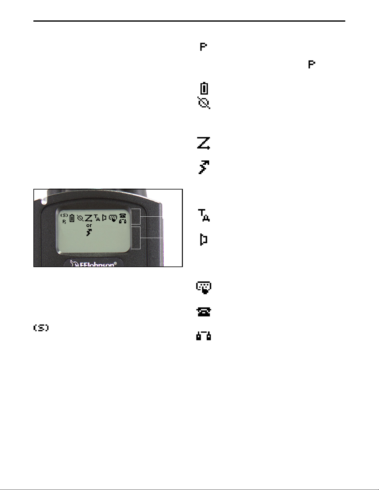
2.4 DISPLAY
Figure 2-4 Graphical Display
The front panel display is shown above. Icons are
typically shown in the upper part of the display and
text messages in the lower part. The icons are as
follows:
- When the scan or the scan list edit mode is
enabled, indicates that the displayed channel is in the
scan list and scanned (see Section 4.8).
- When the scan or the scan list edit mode is
enabled, indicates that the displayed channel is a
priority channel. If dual priority is used, indicates
that it is a second priority channel.
- Low battery indication (see Section 3.4).
- Voice encryption is enabled or an encrypted
call is being received. This indication flashes when an
encrypted call is received on a digital channel (see
Section 11.2.7).
- Priority or radio wide scanning is enabled (see
Section 4.8).
- In the surveillance mode only (see Section
4.7), indicates that the transmitter is keyed. This icon
is displayed in the preceding scan icon location, and
they do not conflict because the scan icon is never
displayed in the transmit mode.
- Repeater talk-around is enabled (see
Section 5.8).
- The Monitor mode is enabled by the Monitor
option switch or menu parameter (see Section 5.3).
The radio can also be programmed so this icon is
displayed when the Normal mode is selected by the
Normal/Selective function (see Section 5.5.2).*
- Keypad programming or another mode is
enabled which allows the user to edit radio parameters.
- An interconnect (telephone) call is in progress
(see Section 6.6).
- A Project 25 or SMARTNET/SmartZone
private (unit-to-unit) call is in progress.
Icon
Area
Tex t
Area
2
* This feature requires firmware 1.16/2.6/3.6/4.2 or later.

13
GENERAL OPERATION
SECTION 3 GENERAL OPERATION
3.1 TURNING POWER ON AND SETTING
VOLUME
3.1.1 POWER UP
Power is turned on and off by the top panel On-
Off/Volume switch. When power is initially turned on,
the following events occur:
•The EFJohnson logo is displayed
•The firmware version number is displayed.
•A self test is performed.
•The currently selected zone is displayed.
•The Individual (Unit/Unique) ID programmed for
the currently selected system is displayed.
•A tone sounds (if tones are enabled) and the alias of
the selected talk group is displayed continuously.
Programming determines if the radio powers up
on the last selected zone or the pre-programmed home
zone. Refer to Section 3.3 for information on the
channel that is selected. The minimum volume level
may be set by programming. This can prevent missed
messages resulting from inadvertently turning the
volume to an inaudible level.
3.1.2 STANDARD AND SOFT POWER DOWN
To turn power off, rotate the On-Off/Volume
control counterclockwise until a click occurs. Power
may remain on for an instant after turn-off occurs.
A soft power down feature* can be programmed
to prevent radio power from being turned off by acci-
dentally turning the on-off/volume control. Any side
button can be programmed for this function in addition
to its normal function. Then for power to turn off, this
button must be pressed during or after power is turned
off in the normal manner using the knob (there is no
time out).
3.1.3 SETTING VOLUME LEVEL
The volume level is adjusted by the top panel
volume control knob or by option buttons programmed
for the Up/Down volume function**. When the
buttons are used, the volume control function of the
knob is disabled (it is still used to switch power).
Volume buttons may be used instead of the knob, for
example, if accidental turning of the volume knob is a
problem.
When the volume control buttons are used, the
number of steps (ticks) required to change the volume
from the minimum level to maximum level is
programmable for 1-50. For example, if “20” is
programmed, there are 20 adjustment steps from
minimum to maximum volume. Only one volume
control button can be programmed if desired and
wrap-around then occurs after the maximum or
minimum level is selected.
The radio can also be programmed so that volume
control is also be disabled by the Keypad Lock feature.
This operation requires PCConfigure Version 1.26 or
later and 51xx software Version 1.16/2.6/3.6 or later.
Refer to Section 3.6 for more information.
The relative volume level can be determined by
the position of the index on the volume knob or by a
reference signal as follows:
•If a key press tone is enabled, a short tone sounds
when a key is pressed.
•If a conventional channel is selected and the
Monitor option switch or menu parameter is
programmed, pressing that switch unsquelches the
receiver and either voice or background noise is
heard (see Section 5.3). If a SMARTNET/Smart-
Zone or P25 Trunked channel is selected, the
receiver cannot be manually unsquelched.
3.2 POWER-UP PASSWORD
3.2.1 GENERAL
The power-up password feature prevents unau-
thorized use of the radio by disabling it when power is
turned on until the proper password is entered. This
feature is enabled or disabled by programming.
* This feature requires 51xx firmware 1.9.0 or later and
PCConfigure 1.20 or later. ** This feature requires 51xx firmware 1.11.0 or later
and PCConfigure 1.21 or later.

GENERAL OPERATION
14
When this feature is enabled, “Enter Pswd” is
briefly displayed when power is turned on. The pass-
word can be 1-8 digit digits in length, and consists of
digits 0-9. It is entered as follows. If an incorrect pass-
word is entered, “INCORRECT” is displayed and it
must be re-entered.
DTMF Keypad Models - Enter the password using
the 1-8 keys and then press the Enter (F2) key when
finished. If a mistake is made, the last digit can be
erased by pressing the F1 (Clear) key.
Limited Keypad Models - Select the proper number
for each position by pressing the Up/Down switch.
When the proper number for a position is displayed,
select it and move on to the next position by pressing
the F2 (Enter) key. If the password is less than eight
digits, press F2 twice after the last digit.
3.2.2 PASSWORD FEATURES WITH LATER
MODELS
With later revised models*, an enhanced pass-
word scheme allows up to four power-on (user) pass-
words, download and upload passwords, and a master
password to be programmed.
The current User password can be changed if the
“Set User Password” option switch or menu param-
eter is programmed. Selecting this function displays
prompts for entering and confirming a new password.
It is recommended that a number key not be used for
this function because the password mode is exited if
that key is pressed to enter a number. Refer to Section
10 for more information on passwords.
3.2.3 PASSWORD FEATURES WITH EARLY
UNREVISED MODELS
With early unrevised models, only one power-on
password is available, and it cannot be changed by the
user. This password must also be entered whenever
programming data is read or written using the PCCon-
figure software. If this password is lost, all personality
information must be erased using the PCTune software
and the radio reprogrammed. Refer to Section 10 for
more information on passwords.
3.3 ZONE AND CHANNEL SELECT
The selected zone and channel are selected and
displayed as follows. For more information on zones
and channels, refer to Section 3.9.5.
Zone Select
The front panel Up/Down switch briefly displays
and changes the alias of the current zone. When not in
special modes such as the menu mode, pressing either
the top or bottom part of this switch once displays the
alias of the current zone. Then quickly pressing it
again changes the selected zone up or down. The
rotary A/B/C switch on the top panel can also be
programmed for zone select (with firmware 1.7.0 or
later). The “A” position then selects Zone 1, “B” Zone
2, and “C” Zone 3 (if applicable).
After the highest programmed zone is displayed,
wrap-around to the lowest programmed zone occurs
and vice versa. The selected zone is also displayed
briefly on power up. If the selected zone alias needs to
be displayed continuously, it must be programmed as
part of the channel alias.
Channel Select
Channels are selected by the rotary 16-position
switch on the top panel. The alias (identification) for
the selected channel/group is displayed continuously
during normal operation.
When an unprogrammed channel is selected,
“UNPROGRAMD” is displayed and a tone sounds (if
tones are enabled). When conventional channels are
selected and the Display Information option key or
menu parameter is programmed, either the channel
frequency or alias can be displayed (see Section 5.9).
The channel selector knob can also be disabled by
programming. Channels must then be directly selected
as described next (if applicable). It may be desirable to
disable the channel select knob when direct selection
is used in order to prevent confusion since the channel
knob then may not indicate the selected channel.
The radio can also be programmed so that the
channel select control is also be disabled by the
Keypad Lock feature (Section 3.6) similar to the
* This feature requires firmware 1.12.1/2.2.1/3.2.1 or
later and PCConfigure 1.22.0 or later.

GENERAL OPERATION
15
volume control described in Section 3.1.3. This opera-
tion requires PCConfigure Version 1.26 or later and
51xx software Version 1.16/2.6/3.6 or later.
Direct Zone/Channel Selection*
The direct Channel Select feature is available if
the Channel Select option switch or menu parameter is
programmed. This feature allows channels to be
directly selected using the DTMF keypad numeric
keys (DTMF models only) or Up/Down switch (all
models).
For direct selection purposes, channels are
numbered sequentially starting with the lowest zone.
Each zone can be programmed with up to 16 channels,
so Zone 1 channels are numbered 1-16, Zone 2 chan-
nels 17-32, and so on as shown below. For example,
Zone 1/Channel 16 is selected by Channel 16, and
Zone 2/Channel 16 is selected by Channel 32.
Proceed as follows to select channels using this
mode:
1. Enable the direct Channel Select mode by pressing
the Channel Select option switch or selecting the
“Chan Selct” menu parameter. The alias and
sequential number of the current channel are
alternately displayed.
2. Select the desired channel using the Up/Down keys
or directly enter it using the 0-9 keys (if available).
If using the 0-9 keys, the radio attempts to display
the entered number after the 3rd digit is entered or
approximately 2 seconds after the last key is
pressed.
3. To exit the this mode and select the entered channel,
press the Channel Select switch again or the F2 key.
To exit without changing the channel, press the F1
key. This mode is also exited automatically without
changing the channel after approximately 1 minute
of no activity.
NOTE: The Channel Select function should probably
not be assigned to a number key because pressing that
key to select a channel then exits the select mode.
Other features of this mode are as follows:
•When using the Up/Down keys, wrap-around to the
lowest zone/channel occurs after the last channel in
the highest programmed zone is displayed and vice
versa. For example, if Zone 1/Channel 5 is the
highest programmed channel, wrap-around occurs
after Zone 1/Channel 16 is displayed.
•When an unprogrammed channel is displayed, the
sequential channel number and “Unprogramd” are
alternately displayed.
•If an invalid channel number is entered using the
0-9 keys, or the F2 or Channel Select option switch
is pressed with “Unprogrammed” displayed, an
error tones sounds, “Invalid” is briefly displayed,
and the displayed channel does not change.
•The rotary Channel Select switch may not correctly
indicate the selected channel after direct channel
selection is used. However, if this switch is enabled
androtated, itselects the channel it is indicating. For
example, if the switch index is pointing to channel 3
and channel 15 of the current zone is being
displayed, rotating it to channel 4 selects channel 4
of the current zone.
•If the rotary Channel Select switch is enabled, the
radio always powers up on the channel it is
selecting.
If it is disabled, the radio can be programmed to
power-up on the last selected or home channel
number of the last selected or home zone**. With
the“LastZone”/“HomeChannel”configuration,the
programmedhomechannelnumberofthelastactive
zone is selected. If it is not programmed, “Unpro-
Seq. Ch. No. Zone Channel
111
16 16
17 2 1
32 16
33 3 1
* This feature requires 51xx firmware 1.5.0 or later and
PCConfigure 1.17 or later. ** This feature requires 51xx firmware 1.9.0 or later and
PCConfigure 1.20 or later.

GENERAL OPERATION
16
grammd” is displayed. With earlier models, the last
selected channel is displayed when powering up on
the last selected zone, and channel 1 is displayed
when powering up on the home zone.
3.4 LOW BATTERY INDICATION
3.4.1 GENERAL
NOTE: If the radio contains encryption keys and is not
programmed for infinite key retention, be sure to reat-
tach a battery within approximately 30 seconds to
prevent the loss of these keys (see following).
A low-battery condition is indicated by the
icon in the display. The battery should be recharged or
replaced as soon after this indication appears. Once
this indication appears, it stays on until power is
cycled.
The following additional low battery indications
and conditions may be enabled by programming:
•A chirp sounds once a minute in the receive standby
and transmit modes.
•A chirp sounds each time the PTT switch is pressed.
•The top panel LED indicator flashes red every 30
seconds in the receive mode.
•Low power is selected when transmitting.
As indicated in the preceding note, the radio may
need to be connected to a constant power source to
preserve the encryption keys in memory. This is
required if “infinite key retention” is not programmed.
To allow the battery to be changed without losing the
keys with this feature disabled, storage capacitors
maintain the supply voltage to memory for approxi-
mately 30 seconds without a battery attached. There-
fore, be sure to reattach a battery within that time. Refer
to Section 8.1.6 for more information on encryption
keys.
There is a battery saver feature that can be
enabled by programming. This feature functions on
trunked channels with firmware 1.7.0 or later only, and
it automatically selects low transmit power when the
receive signal strength (RSSI) indicates that the site is
nearby.
3.4.2 BATTERY CHARGING
NOTE: When a battery is charged while attached to
the radio, make sure radio power is off (see following).
The battery can be charged separately or while
attached to the radio. When it is charged while
attached to the radio, radio power should be turned off.
If it is not, the battery begins slowly discharging when
the charger enters the trickle charge mode. This mode
is indicated by a green Ready indication, and it is
entered automatically when the battery is nearly fully
charged. Gradual discharging occurs in the trickle
mode because the charge current of approximately 50
mA is less than the radio standby current of approxi-
mately 200 mA.
CAUTION: Do not transmit in close proximity to the
charger base (see following).
Do not expose the charger base to high level RF
signals while a battery is being charged because this
may cause a charger fuse to blow (especially in the
UHF range). Radios programmed for SMARTNET/
SmartZone operation, for example, may affiliate while
in the charger which causes them to automatically key.
Therefore, do not leave radio power on while charging
as described above.
3.5 BACKLIGHT
The backlight for the display and option keys can
be programmed to automatically turn on when any key
is pressed. It then automatically turns off after a
programmed delay of 0-7.5 seconds so that battery
drain is minimized. If the Backlight option switch or
menu parameter is programmed, the user can manually
turn the backlight on and off (it then stays on). If the
Surveillance mode is programmed, the backlight is
disabled (see Section 4.7). The radio can be
programmed so that the backlight turns on in the
keypad lock mode when a key is pressed (see next
section).
3.6 KEYPAD LOCK
The Keypad Lock feature temporarily disables
the front panel keys to prevent keys from being acci-
dentally pressed. This feature is available if the
Keypad Lock option switch is programmed. To lock
the keypad, simply press the Keypad Lock option

GENERAL OPERATION
17
switch. Then to unlock the keypad again, press and
hold this switch until a tone sounds (approximately
1 second).
Permanent Keypad Lockout can also be
programmed. The keypad is then permanently disabled
and cannot be enabled by the user. Additional informa-
tion on this feature follows. This describes the opera-
tion with firmware Version 1.16/2.6/3.6/4.2 or later.
Operation with earlier versions may be different.
•A global “Front Keypad Lockout Only” function
can be selected by programming. The front panel
keys but not the side panel option keys are then
disabled by the preceding Keypad Lock and Perma-
nent Lock functions. If this function is not selected,
both the front and side panel keys are disabled. The
PTT switch is never disabled.
•The Channel Selector and Volume controls can be
programmed so that they are locked by the Keypad
Lock function.
•The “Channel Selector Enabled” function can be
programmed globally. If this is not selected, the
channel selector is always disabled regardless of the
Permanent Lockout or Keypad Lock status. Chan-
nels can then be selected only by direct channel
select (see Section 3.3).
•The volume control is permanently disabled if a
Volume Up/Down option switch is programmed
regardless of the Permanent Lockout or Keypad
Lock status. Refer to Section 3.1.3 for more
information.
•There is the option to enable the backlight when a
key is pressed in the Keypad Lock mode. There is
also the option when programming conventional
channels to disable DTMF dialing.
3.7 SETTING SQUELCH
This radio does not have a squelch control. The
squelch level is preset during alignment. If the keypad
programming feature is available (see Section 5.18),
the squelch level can be changed by the user on each
conventional analog channel.
3.8 TRANSMIT DISABLE
Transmitting can be disabled on each conven-
tional, SMARTNET, SmartZone, and P25 Trunked
channel so that the channel is monitor-only. When
transmitting is attempted on a receive-only channel,
“Rx Only” is displayed and an error tone sounds. With
all modes except conventional, this feature is available
only with firmware 1.12.1/2.2.1/3.2.1 or later and
PCConfigure software 1.22.0 or later.
3.9 RADIO OPERATING MODES
3.9.1 GENERAL
Each selectable channel can be programmed for
the conventional (analog or APCO Project 25 digital),
SMARTNET/SmartZone, or APCO Project 25 digital
trunked operating mode. For example, Zone 1/
Channel 1 could be a conventional channel, Zone 1/
Channel 2 a SMARTNET channel, and so on. More
information on these modes follows.
3.9.2 CONVENTIONAL MODE
This is a non-trunked operating mode which
accesses independent radio channels. There is no auto-
matic access to several channels. Selecting a conven-
tional channel selects a transmit and receive frequency
and other channel parameters such as squelch control
coding.
Conventional channels can be either standard
(analog) or Project 25 (digital). With digital operation,
the DSP (Digital Signal Processor) converts the audio
signal to digital data which is sent over the air as
complex tones. Another difference is that analog chan-
nels use Call Guard (CTCSS/DCS) squelch control
and Project 25 channels use a NAC (Network Access
Code) and talk group ID codes.
With Project 25 operation, a NAC is transmitted
and it must match the NAC programmed in the base
equipment and the radio(s) being called for communi-
cation to occur. In addition, to receive standard group
calls, the receiving radio must be programmed to detect
the transmitted talk group ID code.
With conventional operation, a busy channel
condition is detected automatically if the busy channel

GENERAL OPERATION
18
lockout (transmit disable on busy) feature is
programmed. Otherwise, it must be detected manually.
An out-of-range condition is not indicated by special
tones or messages as with SMARTNET operation
because there is no initial data exchange with the
repeater that allows this condition to be detected.
Operating features unique to conventional channels
are described in Section 5.
3.9.3 SMARTNET/SMARTZONE MODE
This is a trunked operating mode in which auto-
matic access is provided to several RF channels. ID
codes are used to select what radios are being called
and what calls are received. Monitoring is performed
automatically and special messages and tones indicate
busy and out-of-range conditions.
SMARTNET and SmartZone operation and
programming is very similar. Basically, SMARTNET
operation is limited to a single repeater site and Smart-
Zone operation allows automatic roaming between
sites. Enhanced SMARTNET/SmartZone features
include roaming (SmartZone only), telephone, private,
and emergency calls, Call Alert™, and messaging.
Either analog or digital signaling may be used (digital
is optional).
When a SMARTNET or SmartZone channel is
selected or the radio is powered up on one of those
channels, it searches for a control channel. Once a
control channel is found, the alias (name) of the
selected channel is displayed and the radio attempts to
register on the radio system. If a control channel could
not be found (because of an out of range condition or
the system ID is not correct, for example), “NO SYS”
(early units) or “Out Rnge” (later units) is displayed
and the radio continues to search for a control channel.
The control channel transmits and receives
system information to and from all radios registered on
the system. Therefore, once a control channel is found,
it is continuously monitored for incoming call infor-
mation and is used to make call requests. The radio
automatically changes to a traffic channel to place and
receive calls and then returns to the control channel
when the call is complete. Operating features unique
to SMARTNET/SmartZone channels are described in
Section 6.
3.9.4 P25 TRUNKED MODE
The P25 Trunked operating features are very
similar to the SmartZone type just described. Since
SmartZone features are also similar to SMARTNET
features, all three modes are described in the
Section 6. Some differences between the P25 Trunking
and SmartZone modes are as follows:
•Digital signaling is always used with P25 calls.
Either analog or digital signaling may be used for
SmartZone calls.
•Calls made to a specific radio in the P25 mode are
called Unit Calls. In the SMARTNET/SmartZone
mode they are called Private Calls.
•Messaging is not available with P25 calls.
•Telephone calls are available with firmware
1.16/2/6/3/6 or later.
•The P25 control channel data rate is 9600 baud and
the digital voice data rate is also 9600 baud. With
SmartZone operation, the control channel data rate
is 3600 baud (both digital and analog calls) and the
narrowband digital voice data rate is 9600 baud.
•The P25 mode uses a system ID, Wide Area
Communications Network (WACN) ID, and RF
Subsystem ID (RFSS). The SmartZone mode does
not use the WACN and RFSS IDs.
•P25Unit IDscanbe1-16,777,215(000001-FFFFFF
hex) and SmartZone Unit IDs can be 1-65,535
(0001-FFFF hex).
3.9.5 SYSTEMS, CHANNELS, AND ZONES
A zone and channel are selected to place and
receive calls. The following describes the relationship
between systems, channels, and zones.
Systems
A system is a collection of channels or talk
groups belonging to the same repeater site. It defines
all the parameters and protocol information required to
access a site. Up to 16 systems of any type can be
programmed.

GENERAL OPERATION
19
The maximum number of channels assignable to
a system is limited to 512. Channels may also be
limited by available memory space as described in the
following information.
Channels
A channel selects a radio (RF) channel or talk
group as follows:
Conventional Analog Mode - A channel selects a
specific radio channel, Call Guard (CTCSS/DCS)
squelch coding, and other parameters unique to that
channel.
Conventional Project 25 Mode - A channel selects a
specific radio channel, NAC squelch coding, talk
group ID, and other parameters unique to that channel.
SMARTNET/SmartZone and Trunked Project 25
Modes - A channel selects a specific talk group,
announcement group, emergency group, and other
parameters unique to that talk group.
A maximum of up to 512 channels can be
programmed with the preceding modes. These chan-
nels can belong to a single system or multiple systems.
The maximum number is also limited by the available
memory. For example, since more memory is required
to program a SMARTNET system than a conventional
system, the total number of channels decreases as the
number of SMARTNET channels increases. The
programming software displays a bar graph which
shows the amount of available memory space that is
used by the current data.
Zones
A zone is a collection of up to 16 channels of any
type. For example, a zone could include 12 conven-
tional channels and 4 SMARTNET channels. One use
of zones may be to program the channels used for
operation in a different geographical areas. The
maximum number of zones is 32.

20
RADIO-WIDE FEATURES
SECTION 4 RADIO-WIDE FEATURES
4.1 OPTION SWITCHES
NOTE: For descriptions of the functions controlled by
these switches, refer to the section of this manual
referenced in the last column of Table 4-1.
Almost all the buttons on this radio are
programmable as follows:
•On the side panel, the three buttons above the PTT
switch (see Figure 2-3 on page 11).
•On the top panel, the rotary three-position switch
and the orange button (see Figure 2-2 on page 11).
•On the front panel, F1 and F2 unless the menu mode
is used (see next section), and F3 and F4.
•With DTMF keypad models, all 12 DTMF keys.
The functions that can be controlled by option
switches are shown in Table 4-1. Each option switch
can be programmed to control a different function in
each of the three operating modes. For example, F3
can control one function when a conventional channel
is selected, another when a SMARTNET/SmartZone
channel is selected, and still another when a Project 25
trunked channel is selected.
4.2 MENU MODE
NOTE: For descriptions of the functions controlled by
the menu mode parameters, refer to the section of this
manual referenced in the last column of Table 4-1.
Most functions that can be controlled by an
option switch can also be controlled by the menu
mode. The functions that can be controlled by the
menu mode are shown in Table 4-1. Functions can be
controlled by both an option switch and a menu
parameter if desired.
When the menu mode is used, the F1 and F2
switches become dedicated menu mode control
switches (see following illustration). The F1 switch is
Back/Clear, and the F2 switch is Menu Select/Enter. If
the menu mode is disabled, these switches can be
programmed for other functions.
Menu Mode Buttons
Only the enabled menu items which apply to the
selected channel type are displayed. For example, if a
conventional channel is selected, only the enabled
functions for conventional channels are displayed.
When in the menu mode, messages continue to be
received on the selected channel. However, the display
does not indicate who is calling. Pressing the PTT
switch exits the menu mode and keys the transmitter.
The menu mode operates as follows:
1. To select the menu mode, press the F2 key. Up to
three menu parameters are then displayed as shown
in the preceding illustration.
2. To scroll up or down through the menu parameter
list, press the Up/Down switch. The selected
parameter is indicated by a dark bar.
3. To display the available modes for a highlighted
parameter, press the F2 switch. The currently
selected mode is indicated by an asterisk.
4. Press the Up/Down switch to highlight the desired
mode. Then press the F2 key to select that mode.
5. To step back to the previous level or exit the menu
mode, press the F1 (Back) key.
4.3 TIME-OUT TIMER
The time-out timer disables the transmitter if it is
keyed continuously for longer than the programmed
Menu
Exit
Back/ Menu
Select/
Enter
Menu
Scroll
Up/Down
Table of contents
Other E.F. Johnson Portable Radio manuals


