E.F. Johnson 7243 LTR-NET User manual

TRUNKED PORTABLE RADIO
SERVICE
MANUAL
First Issue
November 2001
LTR-NET
™
7243
UHF PORTABLE
7.5VDC
1 and 4 Watts
Part No. 242-7243-xxx

7243
LTR-NET™PORTABLE RADIO
SERVICE MANUAL
UHF, 430-470 MHz
Part No. 242-7243-633
Copyright© 2001 by the E.F. Johnson Company
The E.F. Johnson Company, which was founded in 1923, provides wireless communication
systems solutions for public safety, government, and commercial customers. The company
designs, manufactures, and markets conventional and trunked radio systems, mobile and
portable subscriber radios, repeaters, and Project 25 digital radio products.
Viking Head/EFJohnson logo, LTR®, LTR-Net™, and Call Guard®are trademarks of the
E.F. Johnson Company. SMARTNET™and SmartZone®are trademarks of Motorola, Inc. All
other company and/or product names used in this manual are trademarks and/or registered
trademarks of their respective manufacturer.
Information in this manual is subject to change without notice.

TABLE OF CONTENTS
iii November 2001
Part No. 001-7240-001
TABLE OF CONTENTS
1 GENERAL INFORMATION
1.1 SCOPE OF MANUAL. . . . . . . . . . . . . . . . . . . .1-1
1.2 TRANSCEIVER DESCRIPTION. . . . . . . . . . .1-1
1.3 PART NUMBER BREAKDOWN. . . . . . . . . . .1-1
1.4 TRANSCEIVER IDENTIFICATION . . . . . . . .1-1
1.5 TRANSCEIVER TUNING. . . . . . . . . . . . . . . . .1-1
1.6 ACCESSORIES. . . . . . . . . . . . . . . . . . . . . . . . .1-1
1.7 FACTORY CUSTOMER SERVICE . . . . . . . .1-2
1.8 FACTORY RETURNS . . . . . . . . . . . . . . . . . . .1-2
1.9 REPLACEMENT PARTS. . . . . . . . . . . . . . . . .1-3
1.10 INTERNET HOME PAGE. . . . . . . . . . . . . . . . .1-3
1.11 DISASSEMBLING TRANSCEIVER. . . . . . . .1-3
1.12 BATTERY CHARGER INFORMATION. . . . .1-4
General . . . . . . . . . . . . . . . . . . . . . . . . . . . . . . . . 1-4
Fast Charging . . . . . . . . . . . . . . . . . . . . . . . . . . . 1-4
Slow Charging . . . . . . . . . . . . . . . . . . . . . . . . . . 1-4
7243 SPECIFICATIONS. . . . . . . . . . . . . . . . . .1-5
2 OPERATION
2.1 FEATURES. . . . . . . . . . . . . . . . . . . . . . . . . . . . .2-1
General Features. . . . . . . . . . . . . . . . . . . . . . . . . 2-1
LTR-Net Features. . . . . . . . . . . . . . . . . . . . . . . . 2-1
LTR Features . . . . . . . . . . . . . . . . . . . . . . . . . . . 2-1
Conventional Features . . . . . . . . . . . . . . . . . . . . 2-1
2.2 CONTROLS AND DISPLAY . . . . . . . . . . . . . .2-2
Top AND SIDE Controls . . . . . . . . . . . . . . . . . . 2-2
Side Controls . . . . . . . . . . . . . . . . . . . . . . . . . . . 2-2
Display . . . . . . . . . . . . . . . . . . . . . . . . . . . . . . . . 2-2
Front Panel Keys . . . . . . . . . . . . . . . . . . . . . . . . 2-3
2.3 BASIC OPERATION. . . . . . . . . . . . . . . . . . . . .2-5
Power-Up Sequence . . . . . . . . . . . . . . . . . . . . . . 2-5
Backlight Operation . . . . . . . . . . . . . . . . . . . . . . 2-5
Setting Volume Levels . . . . . . . . . . . . . . . . . . . . 2-5
System/Group Display Mode . . . . . . . . . . . . . . . 2-6
System and Group Select . . . . . . . . . . . . . . . . . . 2-6
Keypad Disable (Standard). . . . . . . . . . . . . . . . . 2-6
Keypad Disable (Using PASSWORD) . . . . . . . 2-6
Low Battery Indication. . . . . . . . . . . . . . . . . . . . 2-7
Option Switches . . . . . . . . . . . . . . . . . . . . . . . . . 2-7
Displaying Software Revision Number . . . . . . . 2-7
LTR-Net, LTR, and Conventional Operation. . . 2-7
Localities, Systems, and Groups . . . . . . . . . . . . 2-8
Placing and Receiving Standard Group Calls . . 2-9
Receiving a Standard Group Call. . . . . . . . . . . . 2-9
2.4 GENERAL FEATURES . . . . . . . . . . . . . . . . . .2-9
Bank Select. . . . . . . . . . . . . . . . . . . . . . . . . . . . . 2-9
Call Indicator . . . . . . . . . . . . . . . . . . . . . . . . . . 2-10
Companding . . . . . . . . . . . . . . . . . . . . . . . . . . . 2-10
Emergency Switch . . . . . . . . . . . . . . . . . . . . . . 2-10
Encryption . . . . . . . . . . . . . . . . . . . . . . . . . . . . 2-11
Home System/Group Select . . . . . . . . . . . . . . . 2-11
Option Select. . . . . . . . . . . . . . . . . . . . . . . . . . . 2-11
Power Select . . . . . . . . . . . . . . . . . . . . . . . . . . . 2-11
Proceed (Clear-To-Talk) Tone . . . . . . . . . . . . . 2-11
Receive-Only Groups . . . . . . . . . . . . . . . . . . . . 2-11
Time-Out Timer . . . . . . . . . . . . . . . . . . . . . . . . 2-11
Tone Select . . . . . . . . . . . . . . . . . . . . . . . . . . . . 2-12
2.5 OPTION SWITCHES AND MENU MODE. .2-12
Option Switches . . . . . . . . . . . . . . . . . . . . . . . . 2-12
Menu Mode. . . . . . . . . . . . . . . . . . . . . . . . . . . . 2-12
2.6 SYSTEM AND GROUP SCANNING . . . . . .2-13
General . . . . . . . . . . . . . . . . . . . . . . . . . . . . . . . 2-13
Scan On-Off . . . . . . . . . . . . . . . . . . . . . . . . . . . 2-13
Scan Types . . . . . . . . . . . . . . . . . . . . . . . . . . . . 2-14
LTR-Net Mode Scanning . . . . . . . . . . . . . . . . . 2-14
LTR Mode Scanning. . . . . . . . . . . . . . . . . . . . . 2-14
Conventional Mode Scanning. . . . . . . . . . . . . . 2-15
Scan List Programming. . . . . . . . . . . . . . . . . . . 2-15
Saving Scan List . . . . . . . . . . . . . . . . . . . . . . . . 2-15
Scan Delay and Continue Timers . . . . . . . . . . . 2-15
Transmitting In The Scan Mode. . . . . . . . . . . . 2-16
2.7 DIAL MODE . . . . . . . . . . . . . . . . . . . . . . . . . . .2-16
Introduction. . . . . . . . . . . . . . . . . . . . . . . . . . . . 2-16
Selecting Dial Mode . . . . . . . . . . . . . . . . . . . . . 2-17
Dialing a Number . . . . . . . . . . . . . . . . . . . . . . . 2-17
Sending the Number . . . . . . . . . . . . . . . . . . . . . 2-17
Storing Numbers in Memory . . . . . . . . . . . . . . 2-17
Recalling Numbers From Memory. . . . . . . . . . 2-18
Exiting Dial Mode. . . . . . . . . . . . . . . . . . . . . . . 2-18
2.8 LTR-NET AND LTR FEATURES . . . . . . . . .2-18
Standard Group Calls . . . . . . . . . . . . . . . . . . . . 2-18
Calls on Priority ID Codes . . . . . . . . . . . . . . . . 2-18
Block ID codes and Access Priority . . . . . . . . . 2-19
Transmit Inhibit . . . . . . . . . . . . . . . . . . . . . . . . 2-19
2.9 LTR-NET FEATURES. . . . . . . . . . . . . . . . . . .2-19
LTR-Net Standard Calls . . . . . . . . . . . . . . . . . . 2-19
LTR-Net Special Calls . . . . . . . . . . . . . . . . . . . 2-19
Busy Queuing/Free System Ringback . . . . . . . 2-22
Roaming (Auto-Registration) . . . . . . . . . . . . . . 2-22
Over-The-Air Locality Channel Updates . . . . . 2-24
Transceiver Disable . . . . . . . . . . . . . . . . . . . . . 2-24
Home Channel Aliasing . . . . . . . . . . . . . . . . . . 2-24
2.10 LTR FEATURES . . . . . . . . . . . . . . . . . . . . . . .2-25
Standard Group Calls . . . . . . . . . . . . . . . . . . . . 2-25
Telephone Calls . . . . . . . . . . . . . . . . . . . . . . . . 2-25
LTR Features Not Available. . . . . . . . . . . . . . . 2-26
2.11 CONVENTIONAL FEATURES . . . . . . . . . . .2-26
Busy Indicator. . . . . . . . . . . . . . . . . . . . . . . . . . 2-26
Monitor Mode. . . . . . . . . . . . . . . . . . . . . . . . . . 2-26
Transmit Disable On Busy . . . . . . . . . . . . . . . . 2-27
Squelch Adjust . . . . . . . . . . . . . . . . . . . . . . . . . 2-27
Talk-Around . . . . . . . . . . . . . . . . . . . . . . . . . . . 2-27
Call Guard Squelch. . . . . . . . . . . . . . . . . . . . . . 2-27
External Encoders And Decoders. . . . . . . . . . . 2-28

TABLE OF CONTENTS (CONT’D)
TABLE OF CONTENTS
iv November 2001
Part No. 001-7240-001
2.12 SUPERVISORY TONES . . . . . . . . . . . . . . . .2-28
General Tones. . . . . . . . . . . . . . . . . . . . . . . . . . 2-28
LTR-Net Special Call Tones . . . . . . . . . . . . . . 2-29
LTR Telephone Call Tones . . . . . . . . . . . . . . . 2-29
Display Messages. . . . . . . . . . . . . . . . . . . . . . . 2-30
Menu Mode Messages . . . . . . . . . . . . . . . . . . . 2-31
2.13 TEST FUNCTIONS . . . . . . . . . . . . . . . . . . . . .2-31
2.14 ERROR CODES . . . . . . . . . . . . . . . . . . . . . . .2-31
General . . . . . . . . . . . . . . . . . . . . . . . . . . . . . . . 2-31
Reading Error Codes . . . . . . . . . . . . . . . . . . . . 2-32
3 PROGRAMMING
3.1 GENERAL. . . . . . . . . . . . . . . . . . . . . . . . . . . . . .3-1
Programming Setup . . . . . . . . . . . . . . . . . . . . . . 3-1
Minimum Computer Requirements . . . . . . . . . . 3-1
Remote Programming Interface (RPI) . . . . . . . . 3-1
RPI Cables . . . . . . . . . . . . . . . . . . . . . . . . . . . . . 3-2
EEPROM Data Storage . . . . . . . . . . . . . . . . . . . 3-2
Hardware Hookup. . . . . . . . . . . . . . . . . . . . . . . . 3-2
3.2 MISCELLANEOUS PROGRAM
INFORMATION . . . . . . . . . . . . . . . . . . . . . . .3-2
Basic Windows Knowledge . . . . . . . . . . . . . . . . 3-2
Software Installation. . . . . . . . . . . . . . . . . . . . . . 3-2
Starting Program. . . . . . . . . . . . . . . . . . . . . . . . . 3-3
3.3 MAIN WINDOW DESCRIPTION. . . . . . . . . . .3-3
Title Bar . . . . . . . . . . . . . . . . . . . . . . . . . . . . . . . 3-3
Menu Bar . . . . . . . . . . . . . . . . . . . . . . . . . . . . . . 3-3
Toolbar . . . . . . . . . . . . . . . . . . . . . . . . . . . . . . . . 3-3
Main Window Panes. . . . . . . . . . . . . . . . . . . . . . 3-4
Status Bar . . . . . . . . . . . . . . . . . . . . . . . . . . . . . . 3-4
3.4 PROGRAMMING PROCEDURE . . . . . . . . . .3-4
Introduction . . . . . . . . . . . . . . . . . . . . . . . . . . . . 3-4
Getting Started . . . . . . . . . . . . . . . . . . . . . . . . . . 3-4
Programming Main Radio Parameters . . . . . . . . 3-4
Locality Programming . . . . . . . . . . . . . . . . . . . . 3-5
System Programming . . . . . . . . . . . . . . . . . . . . . 3-6
Group Programming. . . . . . . . . . . . . . . . . . . . . . 3-6
Bank Programming. . . . . . . . . . . . . . . . . . . . . . . 3-6
Programming Transceiver . . . . . . . . . . . . . . . . . 3-6
3.5 FILE MENU. . . . . . . . . . . . . . . . . . . . . . . . . . . . .3-7
3.6 EDIT MENU . . . . . . . . . . . . . . . . . . . . . . . . . . . .3-7
Introduction . . . . . . . . . . . . . . . . . . . . . . . . . . . . 3-7
Edit Radio Type Screen . . . . . . . . . . . . . . . . . . . 3-8
Basic Parameters Screen. . . . . . . . . . . . . . . . . . . 3-8
Timing Parameters Screen . . . . . . . . . . . . . . . . . 3-8
Menu Items Screen. . . . . . . . . . . . . . . . . . . . . . . 3-9
Key Assignment Screen . . . . . . . . . . . . . . . . . . . 3-9
Edit Telephone Numbers Screen . . . . . . . . . . . . 3-9
Edit Locality Screen . . . . . . . . . . . . . . . . . . . . . 3-10
Edit System Screen. . . . . . . . . . . . . . . . . . . . . . 3-11
Edit Groups Screen. . . . . . . . . . . . . . . . . . . . . . 3-11
Edit Banks Screen. . . . . . . . . . . . . . . . . . . . . . . 3-11
Edit Unique ID Screen . . . . . . . . . . . . . . . . . . . 3-11
3.7 TRANSFER MENU . . . . . . . . . . . . . . . . . . . . 3-11
3.8 VIEW MENU . . . . . . . . . . . . . . . . . . . . . . . . . . 3-12
3.9 COMPORTS MENU. . . . . . . . . . . . . . . . . . . . 3-13
3.10 HELP MENU . . . . . . . . . . . . . . . . . . . . . . . . . . 3-13
3.11 ADDITIONAL PROGRAMMING
INFORMATION. . . . . . . . . . . . . . . . . . . . . . 3-13
Program Key . . . . . . . . . . . . . . . . . . . . . . . . . . . 3-13
Multiple Home Repeaters . . . . . . . . . . . . . . . . . 3-13
Channel Number Programming. . . . . . . . . . . . . 3-13
Repeater Numbering . . . . . . . . . . . . . . . . . . . . . 3-13
Specifying RIC-Equipped Repeaters. . . . . . . . . 3-14
Test Locality . . . . . . . . . . . . . . . . . . . . . . . . . . . 3-14
3.12 UPDATING RADIO SOFTWARE . . . . . . . . 3-14
Introduction. . . . . . . . . . . . . . . . . . . . . . . . . . . . 3-14
Data File . . . . . . . . . . . . . . . . . . . . . . . . . . . . . . 3-14
4 CIRCUIT DESCRIPTION
4.1 POWER SWITCHING AND REGULATION. 4-1
Power Switching . . . . . . . . . . . . . . . . . . . . . . . . . 4-1
Five-Volt Regulators (U205, U206) . . . . . . . . . . 4-1
4.2 SYNTHESIZER DESCRIPTION. . . . . . . . . . . 4-1
Introduction. . . . . . . . . . . . . . . . . . . . . . . . . . . . . 4-1
Receive and Transmit VCOs, Buffer
Amplifiers (Q503, Q533-Q535). . . . . . . . . . . 4-1
VCO and TCXO Modulation . . . . . . . . . . . . . . . 4-2
Synthesizer Chip (U202). . . . . . . . . . . . . . . . . . . 4-2
Lock Detect (Q201). . . . . . . . . . . . . . . . . . . . . . . 4-2
DC-DC Converter (U203), Loop Filter. . . . . . . . 4-2
4.3 RECEIVER CIRCUIT DESCRIPTION. . . . . . 4-3
RF Amplifier (Q301), First Mixer (Q302) . . . . . 4-3
IF Amplifier (Q401), Limiter/Mixer/
Detector (U401) . . . . . . . . . . . . . . . . . . . . . . . 4-3
Squelch Circuit (U401) . . . . . . . . . . . . . . . . . . . . 4-4
4.4 TRANSMITTER DESCRIPTION . . . . . . . . . . 4-4
Driver Amplifier (Q101), Power Amplifier
Module (U101). . . . . . . . . . . . . . . . . . . . . . . . 4-4
Antenna Switch and Low-pass Filter . . . . . . . . . 4-4
Power Control . . . . . . . . . . . . . . . . . . . . . . . . . . . 4-4
4.5 CONTROL LOGIC AND DISPLAY. . . . . . . . 4-5
Control Logic . . . . . . . . . . . . . . . . . . . . . . . . . . . 4-5
Display Assembly Description . . . . . . . . . . . . . . 4-5
4.6 RECEIVE AUDIO PROCESSING . . . . . . . . . 4-8
Introduction. . . . . . . . . . . . . . . . . . . . . . . . . . . . . 4-8
Bandpass Filter (U101) . . . . . . . . . . . . . . . . . . . . 4-8
Expander (U204). . . . . . . . . . . . . . . . . . . . . . . . . 4-8
Audio Amplifier (U101, U102). . . . . . . . . . . . . . 4-9
4.7 RECEIVE AND TRANSMIT DATA
PROCESSING . . . . . . . . . . . . . . . . . . . . . . . 4-9
Receive Data Filter/Detector
(U102A/B, U103A/B) . . . . . . . . . . . . . . . . . . 4-9
Transmit Data Filter (U145A/B). . . . . . . . . . . . . 4-9
4.8 TRANSMIT AUDIO PROCESSING. . . . . . . 4-10
Gate (U203), High-Pass Filter (U151) . . . . . . . 4-10

TABLE OF CONTENTS (CONT’D)
TABLE OF CONTENTS
vNovember 2001
Part No. 001-7240-001
Limiter (U151A). . . . . . . . . . . . . . . . . . . . . . . . 4-10
Low-Pass Filter (U146A/B) . . . . . . . . . . . . . . . 4-10
4.9 SMARTNET DATA PROCESSING . . . . . . .4-10
5 ALIGNMENT PROCEDURE
5.1 GENERAL. . . . . . . . . . . . . . . . . . . . . . . . . . . . . .5-1
Introduction . . . . . . . . . . . . . . . . . . . . . . . . . . . . 5-1
Special Test Code Required . . . . . . . . . . . . . . . . 5-1
5.2 LOADING OPERATING CODE . . . . . . . . . . .5-2
General . . . . . . . . . . . . . . . . . . . . . . . . . . . . . . . . 5-2
Saving Personality Information . . . . . . . . . . . . . 5-2
Loading Test Code . . . . . . . . . . . . . . . . . . . . . . . 5-2
5.3 PCTUNE DESCRIPTION . . . . . . . . . . . . . . . . .5-3
PCTune Menu Bar . . . . . . . . . . . . . . . . . . . . . . . 5-3
Radio Tune Screen . . . . . . . . . . . . . . . . . . . . . . . 5-4
5.4 ALIGNMENT PROCEDURE . . . . . . . . . . . . . .5-5
Test Setup. . . . . . . . . . . . . . . . . . . . . . . . . . . . . . 5-5
5.5 FREQUENCY CHECK/ADJUST. . . . . . . . . . .5-6
5.6 HIGH RF POWER ADJUST . . . . . . . . . . . . . .5-6
5.7 LOW RF POWER ADJUST. . . . . . . . . . . . . . .5-6
5.8 MODULATION BALANCE . . . . . . . . . . . . . . .5-6
5.9 DATA DEVIATION . . . . . . . . . . . . . . . . . . . . . .5-6
5.10 AUDIO DEVIATION . . . . . . . . . . . . . . . . . . . . .5-6
5.11 RECEIVE BANDPASS FILTER ADJUST. . .5-7
5.12 RSSI AND SQUELCH ADJUST. . . . . . . . . . .5-7
5.13 OPENING TRANSCEIVER . . . . . . . . . . . . . . .5-7
5.14 RECEIVER PERFORMANCE TESTS . . . . . .5-8
Preliminary Setup. . . . . . . . . . . . . . . . . . . . . . . . 5-8
SINAD Sensitivity . . . . . . . . . . . . . . . . . . . . . . . 5-8
Squelch Sensitivity. . . . . . . . . . . . . . . . . . . . . . . 5-8
Audio Power And Distortion . . . . . . . . . . . . . . . 5-8
Receiver Current Drain. . . . . . . . . . . . . . . . . . . . 5-8
5.15 TRANSMITTER PERFORMANCE TESTS. .5-9
Power Output . . . . . . . . . . . . . . . . . . . . . . . . . . . 5-9
Transmit Frequency . . . . . . . . . . . . . . . . . . . . . . 5-9
Transmit Modulation . . . . . . . . . . . . . . . . . . . . . 5-9
Transmitter Current Drain . . . . . . . . . . . . . . . . . 5-9
5.16 TEST CODE FUNCTIONS. . . . . . . . . . . . . . .5-10
General . . . . . . . . . . . . . . . . . . . . . . . . . . . . . . . 5-10
Test Channels . . . . . . . . . . . . . . . . . . . . . . . . . . 5-10
Modulation Modes . . . . . . . . . . . . . . . . . . . . . . 5-10
Miscellaneous Functions . . . . . . . . . . . . . . . . . 5-10
Parameter Edit Modes . . . . . . . . . . . . . . . . . . . 5-11
6 LTR-NET OVERVIEW
6.1 INTRODUCTION . . . . . . . . . . . . . . . . . . . . . . . .6-1
General . . . . . . . . . . . . . . . . . . . . . . . . . . . . . . . . 6-1
Compatibility With LTR . . . . . . . . . . . . . . . . . . 6-1
LTR-Net Features. . . . . . . . . . . . . . . . . . . . . . . . 6-2
Definitions . . . . . . . . . . . . . . . . . . . . . . . . . . . . . 6-3
6.2 SYSTEM ARCHITECTURE. . . . . . . . . . . . . . .6-3
Introduction. . . . . . . . . . . . . . . . . . . . . . . . . . . . . 6-3
Subscriber Units . . . . . . . . . . . . . . . . . . . . . . . . . 6-3
Repeaters. . . . . . . . . . . . . . . . . . . . . . . . . . . . . . . 6-4
3000-Series Switch . . . . . . . . . . . . . . . . . . . . . . . 6-4
Call Processor . . . . . . . . . . . . . . . . . . . . . . . . . . . 6-5
System and Subscriber Manager. . . . . . . . . . . . . 6-5
6.3 STANDARD GROUP CALLS . . . . . . . . . . . . 6-5
6.4 WIDE AREA GROUP CALLS . . . . . . . . . . . . 6-5
6.5 SPECIAL CALLS. . . . . . . . . . . . . . . . . . . . . . . 6-6
General . . . . . . . . . . . . . . . . . . . . . . . . . . . . . . . . 6-6
Auxiliary Calls . . . . . . . . . . . . . . . . . . . . . . . . . . 6-6
Telephone Calls. . . . . . . . . . . . . . . . . . . . . . . . . . 6-6
Data Calls . . . . . . . . . . . . . . . . . . . . . . . . . . . . . . 6-6
6.6 HOME CHANNEL BACKUP . . . . . . . . . . . . . 6-6
Introduction. . . . . . . . . . . . . . . . . . . . . . . . . . . . . 6-6
Home Repeaters . . . . . . . . . . . . . . . . . . . . . . . . . 6-7
Status Repeaters . . . . . . . . . . . . . . . . . . . . . . . . . 6-7
Home Channel Aliasing . . . . . . . . . . . . . . . . . . . 6-7
6.7 OTHER LTR-NET FEATURES . . . . . . . . . . . 6-7
Unique ID Codes. . . . . . . . . . . . . . . . . . . . . . . . . 6-7
Electronic Serial Number (ESN). . . . . . . . . . . . . 6-8
ESN and Unique ID Requests . . . . . . . . . . . . . . . 6-8
Interrogate . . . . . . . . . . . . . . . . . . . . . . . . . . . . . . 6-8
Kill and Sleep . . . . . . . . . . . . . . . . . . . . . . . . . . . 6-8
Auto-Registration and De-Registration. . . . . . . . 6-8
New Channel Updates. . . . . . . . . . . . . . . . . . . . . 6-9
7 PARTS LIST
Complete Assemblies . . . . . . . . . . . . . . . . . . . . . 7-1
Flexible Cable Assembly. . . . . . . . . . . . . . . . . . . 7-1
Keypad/Display Board Assembly. . . . . . . . . . . . 7-1
RF Board Assembly . . . . . . . . . . . . . . . . . . . . . . 7-2
Logic Board Assembly . . . . . . . . . . . . . . . . . . . . 7-7
Mechanical Parts . . . . . . . . . . . . . . . . . . . . . . . . 7-11
8 SCHEMATIC DIAGRAMS AND
COMPONENT LAYOUTS
Interconnect Schematic . . . . . . . . . . . . . . . . . . . . 8-1
Transceiver-To-RPI Programming Cable . . . . . . 8-1
RF Board Schematic . . . . . . . . . . . . . . . . . . . . . . 8-2
RF Board Top View . . . . . . . . . . . . . . . . . . . . . . 8-3
RF Board Bottom View. . . . . . . . . . . . . . . . . . . . 8-3
Logic Board Schematic. . . . . . . . . . . . . . . . . . . . 8-4
Logic Board Top View . . . . . . . . . . . . . . . . . . . . 8-5
Logic Board Bottom View . . . . . . . . . . . . . . . . . 8-5
Display/Keypad Board Schematic. . . . . . . . . . . . 8-6
Display/Keypad Board Bottom View . . . . . . . . . 8-7
Display/Keypad Board Top View. . . . . . . . . . . . 8-7
Flex Circuit Layout . . . . . . . . . . . . . . . . . . . . . . . 8-7
Transceiver Block Diagram. . . . . . . . . . . . . . . . . 8-8

TABLE OF CONTENTS (CONT’D)
TABLE OF CONTENTS
vi November 2001
Part No. 001-7240-001
LIST OF TABLES
1-1 7243 Portable Accessories . . . . . . . . . . . . . . . . . .1-1
1-2 Charger Indicators . . . . . . . . . . . . . . . . . . . . . . . .1-4
2-1 Menu Mode and Option Switch Functions . . . .2-12
3-1 Menu and Option Sw. Parameter Descriptions .3-10
3-2 Locality Programming Screen Description . . . .3-15
3-3 System Programming Screen Description . . . . .3-16
3-4 Group Programming Screen Description . . . . .3-17
3-5 Bank Programming Screen Description . . . . . .3-19
3-6 Call Guard Codes and Tones . . . . . . . . . . . . . . .3-20
4-1 Microprocessor U208 Pin Descriptions . . . . . . . .4-5
5-1 Test Channels . . . . . . . . . . . . . . . . . . . . . . . . . .5-10
LIST OF FIGURES
1-1 Battery Charger . . . . . . . . . . . . . . . . . . . . . . . . . 1-4
2-1 Top Panel Controls . . . . . . . . . . . . . . . . . . . . . . 2-1
2-2 Display. . . . . . . . . . . . . . . . . . . . . . . . . . . . . . . . 2-2
2-3 Front Panel Keys. . . . . . . . . . . . . . . . . . . . . . . . 2-3
2-4 Programmer Error Code Screen . . . . . . . . . . . 2-32
3-1 Programming Setup. . . . . . . . . . . . . . . . . . . . . . 3-1
3-2 Main Window . . . . . . . . . . . . . . . . . . . . . . . . . . 3-5
3-3 Edit Menu . . . . . . . . . . . . . . . . . . . . . . . . . . . . . 3-7
5-1 Alignment Setup Diagram. . . . . . . . . . . . . . . . . 5-1
5-2 PCTune Tune Radio Screen . . . . . . . . . . . . . . . 5-4
5-3 Internal Adjustment Points . . . . . . . . . . . . . . . . 5-7
6-1 LTR-Net System Diagram. . . . . . . . . . . . . . . . . 6-1
1-1 November 2001
Part No. 001-7240-001
GENERAL INFORMATION
1.1 SCOPE OF MANUAL
This service manual contains operation, program-
ming, alignment, and service information for the E.F.
Johnson 7243 LTR-Net™portable transceiver.
1.2 TRANSCEIVER DESCRIPTION
The 7243 LTR-Net portable transceiver operates
in the UHF 430-470 MHz frequency range. Power
output is selectable for low (1 watt) and high (4 watt)
levels.
A range of up to 16-100 systems are program-
mable, depending on the type and the number of
groups in each. Systems can be programmed for LTR-
Net, LTR, and conventional operation. Each system
can be programmed with up to 99 groups.Currently, all
transceivers have a telephone keypad and three
programmable option switches. Refer to Section 2.1
for more information on operating features.
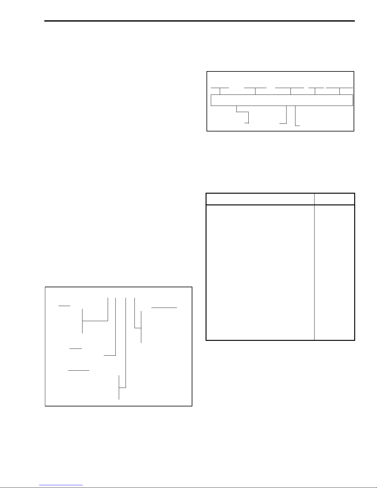
1.3 PART NUMBER BREAKDOWN
The following is a breakdown of the part number
used to identify this transceiver.
1.4 TRANSCEIVER IDENTIFICATION
The transceiver identification number is printed
on a label that is attached to the chassis. The following
information is contained in the identification number:
1.5 TRANSCEIVER TUNING
The field tuning procedure is described in
Section 5.
1.6 ACCESSORIES
The accessories available for this transceiver are
listed in Table 1-1. A brief description of some of
these accessories follows:
Extension Test Cable - This cable is required to
operate the transceiver when it has been opened to
access internal components. It reconnects the keypad/
display board to the audio/logic board.
Programming Hardware - The RPI provides the
interface between the programming computer and
242 - 72 x3 - x x 3
Band Freq Range
Signaling
Type
3 = High Tier, dual BW
1 = VHF*
4 = UHF
8 = 800 MHz*
9 = 900 MHz*
2 = LTR*
4 = Multi-Net*
5 = SMARTNET/SmartZone*
6 = LTR-Net
0 = Full band (800/
900 MHz)*
1 = 400-440 MHz*
3 = 430-470 MHz
5 = 470-512 MHz*
* These configurations are
currently not available.
Table 1-1 7243 Portable Accessories
Accessory Part No.
Battery pack, nickel metal-hydride hi cap 587-7200-140
Rapid charger base, single unit with
120 VAC power supply 585-7200-023
Antenna, hybrid UHF 585-7200-044
Belt clip 585-7200-032
Extension Test Cable Contact Cust Serv
Programming Accessories
LTR-Net 7243/98xx programming
software, CD 023-9998-457
PCTune software and test code, CD 023-9998-489
PCFlash soft. & LTR-Net op. code, CD 023-9998-501
Remote Prog Interface (RPI) 023-9800-000
Programming cable (RPI to xcvr) 597-7200-031
DB9 F to DB9 M 6-ft cable 597-5900-002
DB-25 M to DB-9 F 6-ft cable 597-0005-057
DB-25 F to DB-9 M adapter 515-9000-015
7243 x A 25 1 U 12345
Model Revision
Letter Manufacture
Date Warrant
y
Numbe
r
Week No.
of Year Last Digit of Yea
r
Plant
F
rom P.N.
6 = LTR-Net
SECTION 1 GENERAL INFORMATION

GENERAL INFORMATION
1-2 November 2001
Part No. 001-7240-001
transceiver. The cables from the RPI to computer and
transceiver are not included with the RPI and must be
ordered separately.
Programming Software
The following three types of programming can be
performed with 7243 portable transceivers:
Personality Programming - This programming sets the
parameters that can be different for each transceiver
such as channel frequencies, system and group infor-
mation, and locality information. This programming is
performed by the LTR-Net Programming software,
Part No. 023-9998-457, and described in Section 3 of
this manual.
Transceiver Tuning (PCTune) - Most transceiver
adjustments are made electronically and stored by the
logic. The software used to perform these adjustments
is called PCTune, and it is described in Section 5.
NOTE: To run the PCTune software, the transceiver
must first be re-flashed with temporary test operating
software (see following).
Loading Different Operating Code (PCFlash) - The
PCFlash software is used to upgrade the actual oper-
ating software of the transceiver. This software is
stored in a reprogrammable Flash memory device, and
is the basic operating code of the transceiver.
The LTR-Net operating software may be changed
to upgrade features, correct bugs, or tune the trans-
ceiver. Section 5.2 describes how temporary test oper-
ating code is loaded to tune the transceiver and LTR-
Net operating code is reloaded to restore normal oper-
ation. Test operating code is included on the PCTune
CD, and LTR-Net operating code is included on the
PCFlash CD (see Table 1-1).
1.7 FACTORY CUSTOMER SERVICE
The Customer Service Department of the E.F.
Johnson Company provides customer assistance on
technical problems and the availability of local and
factory repair facilities. Regular Customer Service
hours are 7:30 a.m. - 5:30 p.m. Central Time, Monday-
Friday. The Customer Service Department can be
reached using the following telephone numbers:
Toll-Free: (800) 328-3911
FAX: (507) 835-6969
E-Mail: customerservice@efjohnson.com You can
also e-mail a person directly if you know their first
initial/last name (example: jsmith@efjohnson.com).
NOTE: Emergency 24-hour technical support is also
available at the 800 and preceding numbers during off
hours, holidays, and weekends.
When your call is answered at the E.F. Johnson
Company, you will hear a brief message informing
you of numbers that can be entered to reach various
departments. This number may be entered during or
after the message using a tone-type telephone. If you
have a pulse-type telephone, wait until the message is
finished and an operator will come on the line to assist
you. When you enter some numbers, another number
is requested to further categorize the type of informa-
tion you need.
You may also contact the Customer Service
Department by mail. Please include all information
that may be helpful in solving your problem. The
mailing address is as follows:
E.F. Johnson Company
Customer Service Department
299 Johnson Avenue
P.O. Box 1249
Waseca, MN 56093-0514
1.8 FACTORY RETURNS
Repair service is normally available through local
authorized E.F. Johnson Land Mobile Radio Service
Centers. If local service is not available, the equipment
can be returned to the factory for repair. However, it is
recommended that you contact the Customer Service
Department before returning equipment. A service
representative may be able to suggest a solution to the
problem making return of the equipment unnecessary.
Be sure to fill out a Factory Repair Request Form
#271 for each unit to be repaired, whether it is in or
out of warranty. These forms are available free of
charge by calling Customer Service (see Section 1.7)
or by requesting them when you send a unit in for

GENERAL INFORMATION
1-3 November 2001
Part No. 001-7240-001
repair. Clearly describe the difficulty experienced in
the space provided and also note any prior physical
damage to the equipment. Include this form in the
shipping container with each unit. Your telephone
number and contact name are important as there are
times when the technicians may have specific ques-
tions that need to be answered in order to completely
identify and repair a problem.
When returning equipment for repair, it is also
recommended that you use a PO number or some other
reference number on your paperwork in case you need
to call the repair lab about your unit. These numbers
are referenced on the repair order and make it easier
and faster to locate your unit in the lab.
Return Authorization (RA) numbers are not
necessary unless you have been given one by the Field
Service Department. RA numbers are required for
exchange units or if the Field Service Department
wants to be aware of a specific problem. If you have
been given an RA number, reference this number on
the Factory Repair Request Form sent with the unit.
The repair lab will then contact the Field Service
Department when the unit arrives.
For additional information on factory service, the
Depot Service Department can be contacted at the
following E-mail address:
depotrepair@efjohnson.com
1.9 REPLACEMENT PARTS
Replacement parts can be ordered directly from
the Service Parts Department. To order parts by phone,
dial the toll-free number as described in Section 1.7.
When ordering, please supply the part number and
quantity of each part ordered. E.F. Johnson dealers
also need to give their account number. If there is
uncertainty about the part number, include the desig-
nator (C512, for example) and the model number of
the equipment the part is from.
You may also send your order by mail or FAX.
The mailing address is as follows and the FAX number
is shown in Section 1.7.
E.F. Johnson Company
Service Parts Department
299 Johnson Avenue
P.O. Box 1249
Waseca, MN 56093-0514
1.10 INTERNET HOME PAGE
The E.F. Johnson Company has a site on the
World Wide Web that can be accessed for information
on the company about such things as products,
systems, and regulations. The address is
http://www.efjohnson.com.
1.11 DISASSEMBLING TRANSCEIVER
Proceed as follows to separate the front cover and
chassis:
1. Remove the battery pack and antenna.
2. Remove the two screws located on the back.
3. The front cover andchassis hinge at the top, so care-
fully separate the lower end of the chassis from the
cover and pivot the lower end outward.
4. When reassembling these parts, make sure that the
rubber perimeter gasket is in the groove (if neces-
sary, hold it in the curved area with your fingers).
NOTE: To operate the transceiver with the front and
back separated, the extension test cable listed in Table
1-1 is required.

GENERAL INFORMATION
1-4 November 2001
Part No. 001-7240-001
1.12 BATTERY CHARGER INFORMATION
1.12.1 GENERAL
The battery pack for the 7243 portable contains
six nickel metal hydride (NiMH) batteries connected
in series. Nominal battery pack voltage is 7.5 volts and
battery capacity is 1450 mAH.
The 7243 charger shown in Figure 1-1 has two
slots in which to place a battery. The back slot is for
fast charging and the front slot is for slow charging.
Only the battery can be inserted in the fast charge slot
and the entire transceiver can be inserted in the slow
charge slot if desired. Batteries can be charged in both
slots at the same time. The operation of the LEDs is
shown in Table 1-2.
Figure 1-1 Battery Charger
1.12.2 FAST CHARGING
When a battery is placed in the fast charge slot,
the fast charge indicator briefly flashes red while the
battery is checked to determine if its temperature is
within the required range (0 to +45° C/+32 to +113°F).
If it is, fast charging begins and it changes to steady
red. The fast charge rate is 1320 mA ±100 mA. When
the battery is nearly fully charged, it switches to the
trickle rate of 20-40 mA and the indicator turns green.
It continues at the trickle rate until the battery is
removed from the charger. Approximate charge time
in this slot for a fully discharged battery is 1.5 hours.
The charger uses the ∆T/∆t (change in tempera-
ture/change in time) method to sense that the battery is
nearly fully charged and that switching to the trickle
mode should occur. This method detects when the
battery temperature begins increasing at a faster rate
which normally provides the first indication that the
battery is fully charged.
To provide fail-safe operation, the trickle rate is
also selected if the battery temperature rises above
+50° C (+122° F) or charge time in the rapid mode
exceeds 90 minutes ±20%.
NOTE: Occasionally, a fully charged condition may be
falsely detected and the trickle mode entered after only
a few minutes of rapid charging. To resume normal
rapid charging if this occurs, momentarily lift the
battery out of the slot.
1.12.3 SLOW CHARGING
Batteries charged in the front slot are always
charged at the slow rate of 100-120 mA. The slow
charge indicator turns green when charging is occur-
ring. Typical charge time in this slot for a fully
discharged battery is 20 hours (with transceiver power
turned off if applicable). If the transceiver power is on,
this slot basically maintains the charge of the battery.
Fast Charge Slot Slow Charge Slot
Fast Charge Slot Slow Charge Slot Indicato
r
Indicator
Table 1-2 Charger Indicators
Indication Indicator
Fast Charge Slow Charge
Flashing Red [1] Checking battery
condition N/A
Constant Red Rapid charge mode N/A
Constant Green Trickle charge mode Slow charge mode
Off [2] No charging is
occurring No charging is
occurring
[1] If condition persists, battery temperature may not within
required range (0 to +45° C).
[2] Possible causes are poor contact (clean the charger and
battery contacts) or a defective battery.

GENERAL INFORMATION
1-5 November 2001
Part No. 001-7240-001
7243 SPECIFICATIONS
The following are general specifications intended for use in testing and servicing the transceiver. For current
advertised specifications, refer to the 7243 product information sheet available from your E.F. Johnson sales repre-
sentative. Specifications are subject to change without notice.
GENERAL
Operating Mode LTR-Net/LTR (trunked), and conventional (non-trunked)
Frequency Range 430-470 MHz
Systems Programmable Up to 16-100 depending on system type and number of groups
Groups Programmable Up to 99 per system
Transmit/Receive Separation Within channel spread, 0 MHz conventional talk-around
Channel Spacing 12.5 kHz - 2.5 kHz maximum deviation
25 kHz - 5 kHz maximum deviation
Frequency Stability (tx and rx) 2.0 PPM –22° to +140° F (–30° to +60° C)
Dimensions (with battery and controls) 5.7" H x 2.2" W x 1.4" D
145mm H x 55mm W x 35mm D
Weight (with battery) 15 oz. (410 g)
Power Source 7.5 VDC nickel metal-hydride (NiMH) battery pack, 1450 mAH
Typical Battery Life (5-5-90) 7.3 hours (high power), 9.9 hours (low power)
Compliance FCC parts 15 and 90
Circuit Protection 3-ampere fuse
RECEIVER
Sensitivity 0.35 µV (12 dB SINAD)
Selectivity –65 dB at 25 kHz /–60 dB at 12.5 kHz
Spurious and Image Rejection –65 dB
Intermodulation –65 dB
Audio Output Power Internal Speaker - 0.5 watt (16-ohm load)
External - 1.5 V rms (680-ohm load)
Audio Distortion Less than 5% at rated power (0.5 watt)
Audio Response +1, –3 dB at 6 dB per octave de-emphasis characteristic
Channel Spread 40 MHz
Current Drain Standby (squelched) - 100 mA maximum
Rated Audio Output - 275 mA maximum
TRANSMITTER
High RF Power Output 4.0 watts
Low RF Power Output 1.0 watt
Spurious and Harmonic –60 dB
FM Hum and Noise –40 dB at 25 kHz, –34dB at 12.5 kHz
Audio Distortion 5% maximum at 1 kHz
Audio Frequency Response +1, –3 dB from a 6 dB per octave pre-emphasis characteristic
Audio Modulation 11K0F3E, 16K0F3E
Channel Spread 40 MHz
Current Drain (maximum) Low Power - 950 mA
High Power - 2 A
Load Impedance 50 ohms
Duty Cycle (3-3-54 seconds) 5% (Transmit-Receive-Standby)
2-1 November 2001
Part No. 001-7240-001
OPERATION
SECTION 2 OPERATION
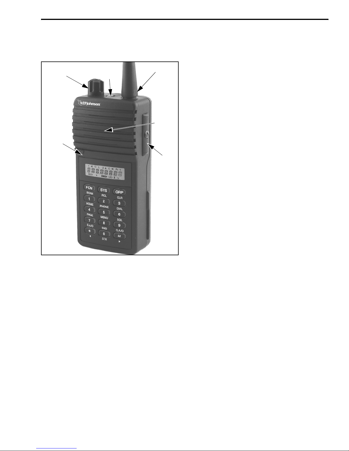
Figure 2-1 Top Panel Controls
2.1 FEATURES
2.1.1 GENERAL FEATURES
The following features are available in all oper-
ating modes (LTR-Net/LTR/conventional).
•Up to 16-100 systems programmable depending on
type (LTR-Net/LTR/conv) and number of groups in
each.
•Up to 99 groups programmable per system
•LTR-Net™, LTR®, and conventional operating
modes
•Unique 8-character system and group identification
tags
•System and group scanning
•User programmable system and group scan lists
•Menu mode to select functions
•Telephone mode for convenient number dialing
•Three programmable option switches
•Keypad lock (with and without password)
•Call indicator
•Time-out timer
•Receive-only groups
•Companding
2.1.2 LTR-NET FEATURES
The following features are available when an
LTR-Net system is selected.
•Roaming (automatic locality search)
•Special calls including telephone, unique ID, and
directed group
•Busy queuing of special calls by radio system
•Transmit inhibit
•Receive priority calls
•Standard group calls (mobile-to-mobile)
•Automatic registration/de-registration
2.1.3 LTR FEATURES
The following features are available when an
LTR system is selected.
•Standard group and telephone calls
•Transmit inhibit
•Receive priority calls
2.1.4 CONVENTIONAL FEATURES
•Busy indicator
•Talk-around
•User-adjustable squelch level
•Monitor mode
•Call Guard®squelch control
•Transmit disable on busy
NOTE: Programming determines the availability of
many of the preceding features.
Antenna Jac
k
On-Off/Volume
Microphone
Speake
r
Option
Switch 1
Accessor
y
Connecto
r
OPERATION
2-2 November 2001
Part No. 001-7240-001
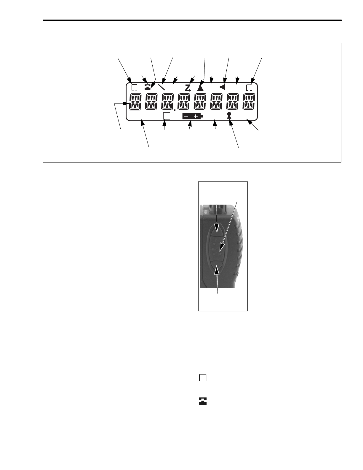
Figure 2-2 Display
BUSY
G
S
UID Tx
P
2
C
L
O
M
System
Scan List Phone
Group Group Scan
List
Scan Call
8-Character
Alphanumeric
MonitorNot Used
Keypad
Dial
Mode Low
Power
Not
Used
Priority
Transmitter
Keyed
Lock
UID/Aux
Group
Low
Battery
Not
Used
Conv Ch
Busy
Display
2.2 CONTROLS AND DISPLAY
2.2.1 TOP AND SIDE CONTROLS
NOTE: These controls are shown in Figure 2-1.
On-Off Volume - Turning this knob clockwise turns
power on and sets the volume level. Turning it coun-
terclockwise to the detent turns power off. Power is on
when information appears in the display. Refer to
Section 2.3.3 for more information on setting volume.
Option Switch 1 - This switch can be programmed to
control a specific function (see Section 2.5.1).
Antenna Jack - Connection point for the antenna.
Accessory Connector - When the protective cover is
removed, this connector can be used to access PTT,
speaker, and microphone lines for transceiver service
and testing. It is also the connection point for the
computer when programming the transceiver.
Battery Release Button (Not shown) - This button is
located on the bottom end of the transceiver, and it is
pressed to release the battery so that it can slide down-
ward and be removed from the radio.
NOTE: Turn off transceiver power before removing
the battery. This ensures that current settings are prop-
erly saved and the de-registration message is sent.
2.2.2 SIDE CONTROLS
Option Switch 2 - This switch can
be programmed to control a
specific function (see Section
2.5.1).
PTT (Push-To-Talk) - This switch
keys the transmitter so that a
message can be transmitted. The
“Tx” icon is displayed when the
transmitter is keyed.
Option Switch 3 - This switch can
be programmed to control a
specific function (see Section
2.5.1).
2.2.3 DISPLAY
8-Character Alphanumeric Display - This area of
the display indicates the selected system and group
(Section 2.3.4), dialed number (Section 2.7), error
conditions, and other information (Section 2.12.4).
-Indicates that the displayed system is in the scan
list and scanned normally (see Section 2.6.7).
- The base portion of this icon is displayed when
the displayed group is programmed for telephone
calls, and the top portion (receiver) is displayed when
the dial mode is selected (see Section 2.7).
S
Option
Switch 2 PTT
Switc
h
Option
Switch 3

OPERATION
2-3 November 2001
Part No. 001-7240-001
- Not currently used.
L- Indicates that low transmit power is selected (see
Section 2.4.8).
- Indicates that the scan mode is selected (see
Section 2.6.1).
- Not currently used.
C- Indicates that a call has been received on a group
programmed for a call indicator (see Section 2.4.2).
Press any key to turn this indication off.
- Indicates that the monitor mode has been enabled
by the Monitor option switch (see Section 2.11.2).
- “P” indicates that the displayed group is an
LTR-Net/LTR priority 1 group, and “P2” indicates that
it is a priority 2 group (see Section 2.8.2).
- Indicates that the displayed group is in the scan
list and scanned normally (see Section 2.6.7).
BUSY - Indicates a carrier is being detected on the
selected conventional channel.
- Not currently used.
- Indicates a low battery condition. The
battery should be recharged soon after this indication
appears (see Section 2.3.8).
UID - Indicates that the displayed group is
programmed for an LTR-Net Unique ID or Directed
Group call (see Section 2.9.1).
- Indicates that the keypad has been locked by
pressing FCN or FCN (see Sections 2.3.6 and
2.3.7).
Tx - Indicates that the transmitter is keyed. This
occurs when the push-to-talk switch is pressed or a
register/de-register message is sent (see Section 2.9.4).
2.2.4 FRONT PANEL KEYS
The front panel keys are shown in Figure 2-3
above. Most keys control two or more functions. The
Figure 2-3 Front Panel Keys
function labeled on the key is usually selected by
simply pressing the key, and the function labeled
under the key is usually selected by first pressing
another key such as the FCN (Function).
In addition, one set of key functions may be
available in the standard mode and another in the dial
mode (see Section 2.7). All key functions except 0-9
can also be assigned to an option switch and controlled
by both as described in Section 2.5.1. Holding a key
down causes repeating if applicable. These keys
operate as follows:
FCN (SCAN)
Standard Mode
FCN - Enables the alternate function of the next key
that is pressed. This alternate function is active for
2 seconds or until another key is pressed, which-
ever occurs first.
FCN SCAN - Turns scanning on and off.
Dial Mode
FCN - Selects the alternate function of various keys
as described in the following information.
SYS (RCL)
Standard Mode
SYS - Pressing repeatedly selects next higher system.
SYS - Selects the next higher system.
SYS - Selects the next lower system.
SYS (xx) - Directly selects specified system.
FCN RCL - Momentarily displays the selected
(revert) system if it is not being displayed.
O
P
2
G
M
#

OPERATION
2-4 November 2001
Part No. 001-7240-001
Dial Mode
RCL - After recalling a number, scrolls through
other numbers programmed in memory.
FCN RCL (0-9) - Recalls the number stored in the
specified memory location.
FCN RCL - Recalls the last number recalled
from memory.
FCN RCL -Recalls the last number sent by FCN
SND.
GRP (CLR)
Standard Mode
The GRP key changes or displays the selected group
similar to the “SYS” key just described.
Dial Mode
CLR - Erases the last digit in the display.
FCN CLR - Erases the entire number in the display.
1 (HOME)
Standard Mode
FCN HOME - Selects the pre-programmed home
system/group.
1 - Pressing this key with the PTT switch pressed
transmits the “1” digit.
Dial Mode
1 - Dials the “1” digit.
2 (PHONE)
Standard Mode
FCN PHONE - Selects the dial mode and the first
telephone group in the current system.
2 - Pressing this key with the PTT switch pressed
transmits the “2” digit.
Dial Mode
2 - Dials the “2” digit.
FCN PHONE - Exits the dial mode and sends the
call termination characters.
3 (DIAL)
Standard Mode
FCN DIAL - Selects the dial mode without
changing the currently selected group.
3 - Pressing this key with the PTT switch pressed
transmits the “3” digit.
Dial Mode
3 - Dials the “3” digit.
FCN DIAL - Exits the dial mode without sending
the call termination characters.
4 (PAGE)
Standard Mode
FCN PAGE - The page function is currently not
available.
4 - Pressing this key with the PTT switch pressed
transmits the “4” digit.
Dial Mode
4 - Dials the “4” digit.
5 (MENU)
Standard Mode
FCN MENU - Selects the menu mode (Section
2.5.2).
5 - Pressing this key with the PTT switch pressed
transmits the “5” digit.
Dial Mode
5 - Dials the “5” digit.
6 (SQL)
Standard Mode
FCN SQL - Selects the squelch adjust mode for
conventional channels (Section 2.11.4).
6 - Pressing this key with the PTT switch pressed
transmits the “6” digit.
Dial Mode
6 - Dials the “6” digit.
7 (S.A/D)
Standard Mode
FCN S.A/D (System Add/Delete) - Changes the
scan list status of the currently displayed system.
The system is in the scan list and scanned
normally if “ ” is displayed when not scanning.
7 - Pressing this key with the PTT switch pressed
transmits the “7” digit.
Dial Mode
7 - Dials the “7” digit.
8 (SEND)
Standard Mode
8 - Pressing this key with the PTT switch pressed
transmits the “8” digit.
#
S

OPERATION
2-5 November 2001
Part No. 001-7240-001
Dial Mode
8 - Dials the “8” digit.
FCN SEND - Automatically transmits the number
in the display (after the system has been accessed
by briefly pressing the PTT switch).
9 (G.A/D)
Standard Mode
FCN G.A/D (Group Add/Delete) - Changes the scan
list status of the currently displayed group. The
group is in the scan list and scanned normally if
“ ” is displayed when not scanning.
9 - Pressing this key with the PTT switch pressed
transmits the “9” digit.
Dial Mode
9 - Dials the “9” digit.
0 (STR)
Standard Mode
FCN STR - Changes between the numeric and alpha
display modes (Section 2.3.4).
0 - Pressing this key with the PTT switch pressed
transmits the “0” digit.
Dial Mode
0 - Dials the “0” digit.
FCN STR (0-9) - Stores the displayed number in
the specified memory location.
()
Standard Mode
- Pressing this key with the PTT switch pressed
transmits the “ ” digit.
SYS - Selects the next lower system (see
preceding “SYS” key description).
GRP - Selects the next lower group (see
preceding “GRP” key description).
FCN - Selects keypad (password) lock feature.
Dial Mode
- Dials the “ ” digit.
FCN - Enters a pause when dialing a telephone
number.
FCN RCL - Recalls the last number recalled
from memory.
()
Standard Mode
- Pressing this key with the PTT switch pressed
transmits the “ ” digit.
SYS - Selects the next higher system (see
preceding “SYS” key description).
GRP - Selects the next higher group (see
preceding “GRP” key description).
FCN - Selects the keypad (standard) lock
feature.
Dial Mode
- Dials the “ ” digit.
FCN - Displays the overflow digits.
FCN RCL - Recalls the last number sent by FCN
SND.
2.3 BASIC OPERATION
2.3.1 POWER-UP SEQUENCE
When power is turned on using the top panel on-
off/volume control, a beep sounds, the backlight turns
on, all segments and icons in the display are momen-
tarily enabled, and the last seven digits of the trans-
ceiver part number (see Section 1.3) are very briefly
displayed. The transceiver is then operational.
2.3.2 BACKLIGHT OPERATION
The display and keypad backlight automatically
turns on for 3 seconds whenever any key is pressed or
power is turned on. If the Backlight menu parameter is
enabled (see Section 2.5.2), selecting “On” enables
this operation and selecting “Off” disables it entirely.
2.3.3 SETTING VOLUME LEVELS
The relative volume level can be determined by
noting the position of the index on the volume knob. A
tone or background noise may also be enabled for use
in setting the volume as follows:
•If key press tones are enabled, a short tone sounds
whenever any key is pressed.
•If a conventional system is selected and the monitor
option switch is programmed (see Section 2.11.2),
press this switch. If someone is talking on the
channel, voice is heard. If no one is talking, the
squelch can be adjusted as described on Section
2.11.4 so that noise is heard. The transceiver cannot
be manually unsquelched when an LTR-Net or LTR
system is selected.
G
#
#
#
#
#
#
#
#

OPERATION
2-6 November 2001
Part No. 001-7240-001
2.3.4 SYSTEM/GROUP DISPLAY MODE
Two system/group display modes can be selected.
One is a numeric format and the other is an alpha tag
format. To switch between these modes, press FCN
STR or select the S/G DISPL menu parameter (see
Section 2.5.2). Turning power off does not change the
selected mode. These modes operate as follows:
Numeric Mode - The system and group numbers are
displayed as “Sxx Gxx” and the group alpha tag is not
displayed. For example, System 1 and Group 2 are
displayed as follows. When system or group scanning
is occurring, the numbers are replaced by dashes (see
Section 2.6.2)
.
Numeric Display Mode
Alpha Tag Mode - The group alpha tag is displayed
instead of the system and group numbers. For
example, the “CAR 220” group is displayed as
follows. When system or group scanning is occurring,
the alpha tag is replaced by “SYS SCAN or “GRP
SCAN” (see Section 2.6.2). To briefly display the
selected system number, press FCN RCL.
Alpha Tag Display Mode
2.3.5 SYSTEM AND GROUP SELECT
Systems and groups are selected as follows.
When the system is changed, the last selected group in
the new system is displayed.
•To increase the selected system, press SYS repeat-
edly or press SYS and then ( ). Likewise, to
increasetheselectedgroup,pressGRPrepeatedlyor
press GRP . Holding the key down causes the
function to repeat. After the highest system orgroup
is selected, wrap-around to the lowest system or
group occurs.
•To decreasethe selected system,press SYS and then
( ). Likewise, to decrease the selected group,
press GRP . As when selecting a system, holding
the key down causes the function to repeat, and
after the lowest system or group is selected, wrap-
around occurs.
•To directly select a system or group number, press
SYS or GRP and then the number of the desired
system or group. For example, to select Group 9,
press GRP, 0, 9. A leading “0” must be entered to
select systems and groups 1-9.
2.3.6 KEYPAD DISABLE (STANDARD)
Occasionally, the front panel keys may be acci-
dentally pressed, for example, if the transceiver is
carried on a belt and it brushes against an object. To
prevent this from happening, the front panel keys and
option switches can be quickly disabled by simply
pressing FCN . The disabled condition is indicated
by the icon.
If a key or option switch is then pressed, all that
happens is “LOCKED” is displayed. The on-off/
volume and PTT controls remain functional so that
calls can be received and transmitted. To re-enable the
keys and option switches, press FCN again.
Turning power off does not change the selected mode.
2.3.7 KEYPAD DISABLE (USING PASSWORD)
To prevent unauthorized changing of the selected
system and group and other operating parameters, the
keypad and option switches can be disabled using a
password. To select this disable mode, press FCN .
“PASSWORD” is then displayed to indicate that a
four-digit unlock password must be entered. This pass-
word can be any four-digit number except “0000”. The
desired password must be entered twice (the second
time is to confirm it). The keypad and option switches
are then disabled as indicated by “LOCKED” and
in the display.
If a key or option switch is then pressed, all that
happens is “PASS LCK” is displayed. To re-enable the
keypad and option switches, press FCN again and
re-enter the four-digit password. As with the disable
mode described in the preceding section, the on-off/
volume and PTT controls remain active so that calls
can be received and transmitted normally.
#
#
#

OPERATION
2-7 November 2001
Part No. 001-7240-001
NOTE: This password is not preprogrammed and
there is no override procedure. Therefore, if it is
forgotten, the transceiver must be reprogrammed to
return it to normal operation.
2.3.8 LOW BATTERY INDICATION
When the battery voltage drops to the point where
recharging is required, the icon is indicated in
the bottom part of the display. In addition, a beep
sounds when this indication initially appears and
whenever the push-to-talk switch is released (if the
key press tone is enabled). The battery should be
recharged as soon as practical after this indication
appears.
Low transmit power is automatically selected
during a low battery condition (indicated by “L” in
display), and the current settings of switches and other
parameters continue to be saved in memory. The low-
battery indication is reset by turning power off and
then on again.
2.3.9 OPTION SWITCHES
This transceiver has three option switches that
can be programmed to control various functions as
described in Section 2.5.1. These switches are the
push-button switch on the top panel, the switch imme-
diately above, and the switch immediately below the
PTT switch on the side panel.
2.3.10 DISPLAYING SOFTWARE REVISION
NUMBER
To display the operating (Flash) software version
number, turn power on with PTT switch pressed. The
version number is displayed as “VER x.xx”. To return
to normal operation, press FCN RCL or cycle power.
The software version number can also be read using
the programmer by selecting the Transfer > Read
Factory Info function (see Section 3.7).
2.3.11 LTR-NET, LTR, AND CONVENTIONAL
OPERATION
Introduction
This transceiver can be programmed to operate in
the LTR-Net, LTR, and conventional modes. Each
selectable system can be programmed to select a
locality programmed for one of these modes. The type
of operation that is programmed is determined by the
type of repeater equipment being accessed. The differ-
ences in operation are described in the following infor-
mation and also noted elsewhere as required.
LTR-Net and LTR Operation
The LTR-Net mode provides the most operating
features. Some features available only in the LTR-Net
mode include roaming (automatic locality search),
unique ID calls, and directed group calls. LTR-Net
features are described in Sections 2.8, and a general
overview of LTR-Net operation is located in Section 6.
Operation in the LTR mode is similar to the LTR-
Net mode except that the preceding and some other
LTR-Net features are not available.The types of calls
that can be placed in the LTR mode are standard group
(mobile-to-mobile) and telephone. LTR features are
described in Sections 2.8 and 2.10 and also in the LTR
Application Note, Part No. 009-0001-020, Rev. 8 or
later.
Both the LTR-Net and LTR modes provide auto-
matic channel selection (trunking) and monitoring
before transmitting. Special tones and display
messages indicate busy and out-of-range conditions.
Telephone calls can be placed almost as conveniently
as with your home telephone. The information
programmed in LTR-Net and LTR systems and groups
is described in Section 2.3.12.
Conventional Operation
In the conventional mode, selecting a system
selects a radio channel, and selecting a group selects
the squelch control coding (CTCSS, CDCS, or carrier)
and other parameters (see Section 2.3.12). The squelch
level must be adjusted manually as described in
Section 2.11.4 to properly receive conventional calls.
With conventional operation, an out-of-range
condition is not indicated by a special tone or display
message because there is no data handshake with a
repeater that allows this condition to be detected. A
busy condition is detected automatically if the
Transmit Disable On Busy feature is used (see Section
2.11.3). Otherwise, it must be detected manually as
follows. Refer to Section 2.11 for more information on
conventional operation.

OPERATION
2-8 November 2001
Part No. 001-7240-001
To manually monitor a conventional channel
before transmitting to determine if it is being used by
someone else, proceed as follows:
Using Busy Indicator - With scanning disabled and
the squelch control adjusted as described in Section
2.11.4, note if “BUSY” is indicated in the lower part
of the display. If it is, a carrier is being detected on the
currently selected conventional system (channel). If
this indication is not displayed, the channel is not busy
and the message can be transmitted.
Using Monitor Mode - If scanning, pressing the
Monitor option switch (see Section 2.5.1) disables
scanning and enables the monitor mode indicated by
in the display. The monitor mode disables squelch
control features so that all messages are heard. If none
are heard, the channel is free and the message can be
transmitted. Refer to Section 2.11.2 for more informa-
tion on monitoring.
2.3.12 LOCALITIES, SYSTEMS, AND GROUPS
When any call is placed, a locality, system, and
group are selected. Definitions of these terms follow.
Localities
An LTR-Net or LTR locality is typically a single
repeater site in which the repeaters are co-located and
interconnected by a common bus to form a trunked
channel group. A conventional locality may or may
not include repeaters at the same physical site. A
locality can include up to twenty repeaters.
Unique locality parameters include the channel
frequencies and bandwidth of each repeater at the site,
the status repeater (LTR-Net only), and the repeaters
equipped with telephone interconnect (LTR only) and
companding. Up to approximately 25 LTR-Net or 60
LTR/conventional localities can be programmed (the
maximum number decreases as the number of banks,
systems, and groups increases).
Systems
Systems are a collection of groups and other
information unique to that system (see next para-
graph). Each system is linked to one of the
programmed localities, and up to 99 systems can be
programmed. Each system is programmed with a
unique alpha tag and can have a different display
number in each bank (see Section 2.4.1).
LTR-Net and LTR systems are programmed with
the home repeater number, a collection of groups, and
a transmit inhibit block of ID codes (see Section
2.8.4). The home repeater number and group ID code
form the address for group calls. In addition, the home
repeater is monitored for incoming call information
(the status repeater serves as a backup with LTR-Net
operation).
Conventional systems select a specific radio
channel and include one or more groups, each of
which can select unique coded squelch information on
that channel (see following).
Groups
The groups assigned to a system select individual
call information. Up to 99 groups can be assigned to
each system. With all three types of operation, each
group is programmed with a unique alpha tag, group
scan, call indicator, and other information. The avail-
able group types are as follows.
LTR-Net Group Types
Dispatch - Used to place and receive standard group
(mobile-to-mobile) calls. Encode and decode IDs
from 1-239 can be specified.
Telco - Used to place and receive telephone calls.
Auxiliary - Used to place and receive unique ID and
directed group calls.
Data - Currently not available.
LTR Group Types
Dispatch - Used to place and receive standard group
(mobile-to-mobile) calls. Encode and decode IDs
from 1-250 can be specified when accessing an LTR
locality (site). If an LTR-Net locality is being
accessed, IDs from 1-239 can be specified.
Telco - Used to place and receive telephone calls. A
RIC (interconnect) ID is also specified. This code is
one that has been reserved on the repeater system
for telephone calls.

OPERATION
2-9 November 2001
Part No. 001-7240-001
Conventional Group Types
Only dispatch calls can be programmed with
conventional operation. Conventional groups select
Call Guard squelch, group scan, call indicator, and
other information.
2.3.13 PLACING AND RECEIVING STANDARD
GROUP CALLS
General
These calls are between two or more mobile or
control station transceivers. The main difference
between these calls and the other types is that no
number is dialed using the keypad. The following
procedure applies to all three types of operation (LTR-
Net, LTR, and conventional).
Placing a Standard Group Call
1. Turn transceiver power on and set the volume as
described starting with Section 2.3.1. With conven-
tional operation, also make sure that the squelch is
properly set as described in Section 2.11.4.
2. Select the system and group of the mobile being
called as described in Section 2.3.5.
3. If a conventional call is being placed, monitor the
channel manually or automatically as described in
Section 2.3.11.
4. Press (and hold) the microphone PTT (push-to-talk)
switch to talk and release it to listen. Operation with
LTR-Net, LTR, and conventional calls is as follows:
LTR-Net and LTR Operation
•If tones are enabled, the proceed tone sounds
shortly afterthe PTT switch ispressedif the radio
system was successfully accessed (see Section
2.4.9). If tones are disabled, no tone sounds when
the system is successfully accessed.
•If the radio system is busy, the busy tone sounds
(seeSection2.12)and“BUSY” is indicatedin the
display. If thePTT switchcontinuestobepressed,
the system is accessed as soon as it is free.
•If theradio system could not be accessed because
of an out-of-range condition or some other
reason, the intercept tone sounds (see Section
2.12) and “NO ACCES” is indicated in the
display. The PTT switch must then be released
and pressed again to make another access
attempt.
•When responding, busy or no access conditions
may also occur the same as when placing a call
because the system is re-accessed for each
transmission with these calls.
Conventional Operation
•If the channel is busy and the Transmit Disable
On Busy feature is programmed (see Section
2.11.3), “DSBL BSY” is indicated in the display
and the transmitter is disabled. Any channel
activity is heard while the PTT switch is pressed.
•Otherwise, busy and out-of-range conditions are
not indicated and speaking can begin when the
PTT switch is pressed (if the channel isnot busy).
If the proceed tone is enabled on conventional
systems, it indicates when speaking can begin but
does not indicate that the channel is free or has
been successfully accessed.
2.3.14 RECEIVING A STANDARD GROUP CALL
1. Selectorscanthesystemandgroupprogrammedfor
the call you want to receive (see Section 2.6.1 for
scan information).
2. When the message is received, the display changes
to the system and group of the call. Press the PTT
switch to talk and release it to listen. If scanning or
if a priority call is received, a response may not
automatically occur on the group of the call. Refer
to Section 2.6.10 for more information.
2.4 GENERAL FEATURES
2.4.1 BANK SELECT
A bank is a collection of selectable systems that
have been set up for a specific application. For
example, one bank could be programmed for operation
in Minneapolis and another for operation in
This manual suits for next models
1
Table of contents
Other E.F. Johnson Portable Radio manuals


