Ecoair D60 User manual
C.P.N. : 89290720 GB
DATE : AUGUST 2000
D60 D75
D100 D102
OPERATION AND MAINTENANCE MANUAL
1090200D102 SERIAL No: –>>
1085120D100 SERIAL No: –>>
1080110D75 SERIAL No: –>>
1075080D60 SERIAL No: –>>
This manual contains
important safety information
and must be made available to
personnel who operate and
maintain this machine.
Manual Closed Out
Machine no longer in production


Machine models represented in this manual may be used in various locations worldwide. Machines sold and
shipped into European common market countries requires that the machine display the EC Mark and conform
to various directives. In such cases, the design specification of this machine has been certified as complying
with EC directives. Any modification to any part is absolutely prohibited and would result in the CE certification
and marking being rendered invalid. A declaration of that conformity follows:
EC DECLARATION OF CONFORMITY WITH EC DIRECTIVES
98/37/EC, 93/68/EEC, 89/336/EEC
WE,
ECOAIR
GEWERBEALLE 17
D–45478 MÜLHEIM
DEUTSCHLAND
DECLARE THAT, UNDER OUR SOLE RESPONSIBILITY FOR MANUFACTURE AND SUPPLY,
THE PRODUCT(S)
D60 D75 D100 D102
TO WHICH THIS DECLARATION RELATES, IS (ARE) IN CONFORMITY WITH THE PROVISIONS
OF THE ABOVE DIRECTIVES USING THE FOLLOWING PRINCIPAL STANDARDS.
EN29001, EN292, EN60204–1, EN1012, EN50081, EN50082
ISSUED AT MÜLHEIM ON 01/01/2001 BY G BAUER, GENERAL MANAGER
GEORG BAUER

CONTENTS & ABBREVIATIONS
1
D60 D75
D100 D102
CONTENTS
1 CONTENTS
2 FOREWORD
3 ISO SYMBOLS
8 SAFETY
10 GENERAL INFORMATION
25 INSTALLATION / HANDLING
28 OPERATING INSTRUCTIONS
37 MAINTENANCE
45 FAULT FINDING
47 OPTIONS
ABBREVIATIONS & SYMBOLS
#### Contact ECOAIR for serial number
–>#### Up to Serial No.
####–> From Serial No.
*Not illustrated
Option
NR Not required
AR As required
SM Sitemaster/Sitepack
HA High ambient machine
WC Watercooled machine
AC Aircooled machine
ERS Energy recovery system
T.E.F.C. Totally enclosed fan cooled motor (IP54)
O.D.P. Open drip proof (motor)
DGermany
DK Denmark
ESpain
FFrance
GB Great Britain
IItaly
NNorway
NL Netherlands
PPortugal
SSweden
SF Finland

FOREWORD 2
D60 D75
D100 D102
The contents of this manual are considered to be proprietary and
confidentialto ECOAIR and should not be reproduced without the prior
writtenpermission of ECOAIR.
Nothing contained in this document is intended to extend any
promise,warranty or representation, expressed or implied, regarding
the ECOAIR products described herein. Any such warranties or other
termsand conditions of sale of products shall be in accordance with the
standard terms and conditions of sale for such products, which are
availableupon request.
This manual contains instructions and technical data to cover all
routineoperation and scheduled maintenance tasks by operation and
maintenance staff. Major overhauls are outside the scope of this
manual and should be referred to an authorised ECOAIR service
department.
The design specification of this machine has been certified as
complying with E.C. directives. Any modification to any part is
absolutely prohibited and would result in the CE certification and
markingbeing rendered invalid.
All components, accessories, pipes and connectors added to the
compressedair system should be:
. of good quality, procured from a reputable manufacturer and,
wherever possible, be of a type approved by ECOAIR.
. clearly rated for a pressure at least equal to the machine maximum
allowableworking pressure.
. compatible with the compressor lubricant/coolant.
. accompaniedwith instructions for safe installation, operation and
maintenance.
Details of approved equipment are available from ECOAIR Service
departments.
The use of repair parts other than those included within the ECOAIR
approved parts list may create hazardous conditions over which
ECOAIR has no control. Therefore ECOAIR cannot be held
responsible for equipment in which non–approved repair parts are
installed.
ECOAIR reserves the right to make changes and improvements to
products without notice and without incurring any obligation to make
such changes or add such improvements to products sold previously.
The intended uses of this machine are outlined below and examples
of unapproved usage are also given, however ECOAIR cannot
anticipateevery application or work situation that may arise.
IF IN DOUBT CONSULT SUPERVISION.
This machine has been designed and supplied for use only in the
followingspecified conditions and applications:
.Compression of normal ambient air containing no known or
detectableadditional gases, vapours. or particles
.Operationwithin the ambient temperature range specified in the
GENERAL INFORMATION
section of this manual.
The use of the machine in any of the situation types listed in
table 1:–
a) Is not approved by ECOAIR,
b) May impair the safety of users and other persons, and
c) May prejudice any claims made against ECOAIR.
TABLE 1
Use of the machine to produce compressed air for:
a) direct human consumption
b) indirect human consumption, without suitable filtration and purity
checks.
Use of the machine outside the ambient temperature range
specifiedin the
GENERAL INFORMATION SECTION
of this manual.
Use of the machine where there is any actual or foreseeable risk of
hazardouslevels of flammable gases or vapours.
Use of the machine fitted with
non ECOAIR approved components.
Use of the machine with safety or control components missing or
disabled.
The company accepts no responsibility for errors in translation of
this manual from the original English version.
COPYRIGHT 2000
INGERSOLL–RAND COMPANY

ISO SYMBOLS3
D60 D75
D100 D102
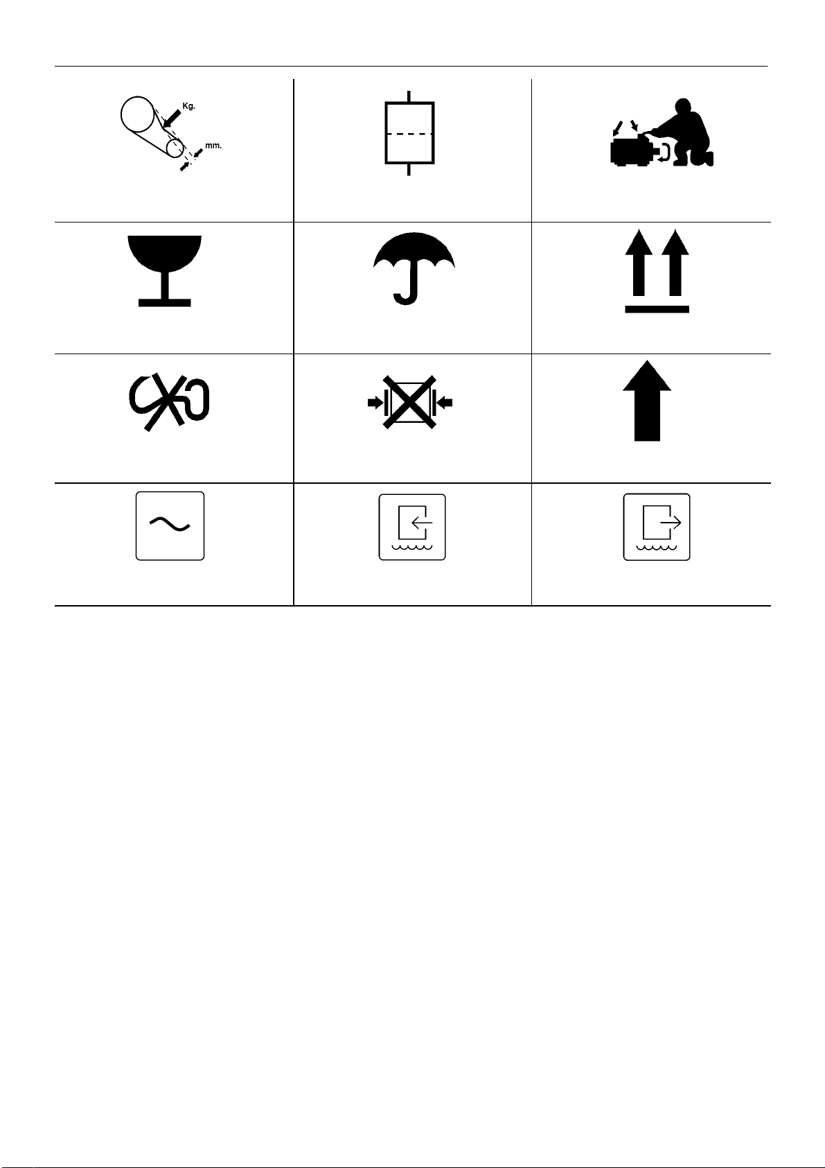
GRAPHIC FORM AND MEANING OF ISO SYMBOLS
Prohibition / Mandatory Information / Instructions Warning
WARNING: Electrical shock risk.WARNING – Pressurised vessel. WARNING – Hot surface.
WARNING – Pressure control. WARNING – Corrosion risk. WARNING – Air/gas flow or Air discharge.
X,XBAR
WARNING – Pressurised component or
system. WARNING – Hot and harmful exhaust gas. WARNING – Maintain correct tyre pressure.
(Refer to the GENERAL INFORMATION
section of this manual).
0C
WARNING – Flammable liquid.WARNING – Before connecting the tow bar
or commencing to tow consult the
operation and maintenance manual.
WARNING – For operating temperature
below 0C, consult the operation and
maintenance manual.

ISO SYMBOLS 4
D60 D75
D100 D102
WARNING – Do not undertake any
maintenance on this machine until the
electrical supply is disconnected and the air
pressure is totally relieved.
WARNING – Consult the operation and
maintenance manual before commencing
any maintenance.
Do not breathe the compressed air from this
machine.
Do not remove the Operating and Maintenance
manual and manual holder from this machine. Do not stack. Do not operate the machine without the guard
being fitted.
Do not stand on any service valve or other
parts of the pressure system. Do not operate with the doors or enclosure
open. Do not use fork lift truck from this side.
XX
km/h
Do not exceed the trailer speed limit. No naked lights. Do not open the service valve before the
airhose is attached.
Use fork lift truck from this side only. Emergency stop. Tie down point

ISO SYMBOLS5
D60 D75
D100 D102
Lifting point. On (power). Off (power).
a
Read the Operation and Maintenance manual
before operation or maintenance of this
machine is undertaken. When parking use prop stand, handrake and
wheel chocks. Contains asbestos.
SET SEQUENCER STATUS LOAD
SEQUENCER (AUTOMATIC CONTROL) COMPRESSOR OFF LOAD (UNLOADED)
RESET COMPRESSOR STATUS MODULATE
MALFUNCTION POWER SOILED FILTER
POWER INLET ELECTRIC MOTOR HOURS

ISO SYMBOLS 6
D60 D75
D100 D102
COOLANT SEPARATOR PRESSURE AIR DISCHARGE
PRESSURISED TANK ON / OFF CYCLE COOLANT FILTER
AIR FILTER ON / OFF PUSH BUTTON COOLANT PRESSURE
AIR PRESSURE STAR DELTA IEC 617–7 AUTOMATIC RESTART
HEAT EXCHANGER MAINTENANCE MAINTENANCE PROHIBITED
COOLANT DRAIN CONDENSATE DRAIN PRESSURE CONTROL
MANUAL (SELECT) TEMPERATURE HIGH TEMPERATURE
ISO SYMBOLS7
D60 D75
D100 D102
BELT TENSION FILTER MOTOR LUBRICATION
FRAGILE KEEP DRY THIS WAY UP
USE NO HOOKS NO SIDE CLAMPS ROTATION
POWER INLET (AC) WATER IN WATER OUT

SAFETY 8
D60 D75
D100 D102
WARNINGS
Warnings call attention to instructions which must be followed
precisely to avoid injury or death.
CAUTIONS
Cautions call attention to instructions which must be followed
precisely to avoid damaging the product, process or its surroundings.
NOTES
Notes are used for supplementary information.
General Information
Ensure that the operator reads and
understands
the decals and
consults the manuals before maintenance or operation.
Ensure that the Operation and Maintenance manual, and the
manualholder, are not removed permanently from the machine.
Ensure that maintenance personnel are adequately trained,
competentand have read the Maintenance Manuals.
Compressed air and electricity can be dangerous. Before
undertakingany work on the compressor, ensure that the electrical
supply has been isolated and the compressor has been relieved of all
pressure.
Make sure that all protective covers are in place and that the
canopy/doorsare closed during operation.
Installation of this compressor must be in accordance with
recognisedelectrical codes and any local Health and Safety Codes.
The use of plastic bowls on line filters without metal guards can be
hazardous. Their safety can be affected by either synthetic lubricants,
or the additives used in mineral oils. Metal bowls should be used on a
pressurised system.
Compressed air can be dangerous if incorrectly handled. Before
doingany work on the unit, ensure that all pressure is vented from the
system and that the machine cannot be started accidentally.
Compressed air
Ensurethat the machine is operating at the rated pressure and that
the rated pressure is known to all relevant personnel.
All air pressure equipment installed in or connected to the machine
must have safe working pressure ratings of at least the machine rated
pressure.
If more than one compressor is connected to one common
downstreamplant, effective check valves and isolation valves must be
fittedand controlled by work procedures, so that one machine cannot
accidently be pressurised / over pressurised by another.
Compressedair must not be used for a direct feed to any form of
breathing apparatus or mask.
The discharged air contains a very small percentage of compressor
lubricatingoil and care should be taken to ensure that downstream
equipmentis compatible.
If the discharged air is to be ultimately released into a confined
space, adequate ventilation must be provided.
When using compressed air always use appropriate personal
protectiveequipment.
All pressure containing parts, especially flexible hoses and their
couplings,must be regularly inspected, be free from defects and be
replacedaccording to the Manual instructions.
Compressed air can be dangerous if incorrectly handled. Before
doingany work on the unit, ensure that all pressure is vented from the
system and that the machine cannot be started accidentally.
Avoid bodily contact with compressed air.
The safety valve located in the separator tank must be checked
periodically for correct operation.
Materials
The following substances are used in the manufacture of this
machineand
may
be hazardous to health if used incorrectly:
. preservative grease
. rust preventative
. compressor coolant
AVOID INGESTION, SKIN CONTACT AND INHALATION OF
FUMES
For further information, consult Material Data Sheets ECOP006/95.
Shouldcompressor lubricant come into contact with the eyes, then
irrigatewith water for at least 5 minutes.
Should compressor lubricant come into contact with the skin, then
wash off immediately.
Consult a physician if large amounts of compressor lubricant are
ingested.
Consult a physician if compressor lubricant is inhaled.
Never give fluids or induce vomiting if the patient is unconscious or
havingconvulsions.
Transport
When loading or transporting machines ensure that the specified
liftingand tie down points are used.
Electrical
Keep all parts of the body and any hand–held tools or other
conductiveobjects, away from exposed live parts of the compressor
electrical system. Maintain dry footing, stand on insulating surfaces
and do not contact any other portion of the compressor when making
adjustments or repairs to exposed live parts of the compressor
electricalsystem.
Close and lock all access doors when the compressor is left
unattended.
Do not use extinguishers intended for Class A or Class B fires on
electrical fires. Use only extinguishers suitable for class
BC
or class
ABC
fires.
Attemptrepairs only in clean, dry, well lighted and ventilated areas.
Connect the compressor only to electrical systems that are
compatiblewith its electrical characteristics and that are within it’s rated
capacity.

SAFETY
9
D60 D75
D100 D102
Condensate disposal
Condensatecannot be discharged into fresh/surface water drains.
In some regions compressor condensate containing ECOOL can be
fed directly into a drainage system that has downstream sewerage
treatment.
As waste water regulations vary by country and region it is the
responsibilityof the user to establish the limitations and regulations in
theirparticular area. ECOAIR and its associated distributors are happy
to advise and assist in these matters.
Coolant disposal
Steps to be taken in the case of spillage: Soak up with a suitable
absorbentmaterial, then sweep into a plastic bag for disposal.
Burn in an approved incinerator, or according to local area or
country regulations.
For further information, consult Material Data Sheets ECOP006/95.
The above information contains data supplied in support of United
Kingdom
Control of Substances Hazardous to Health
(C.O.S.H.H.)
regulations.
GENERAL INFORMATION 10
D60 D75
D100 D102
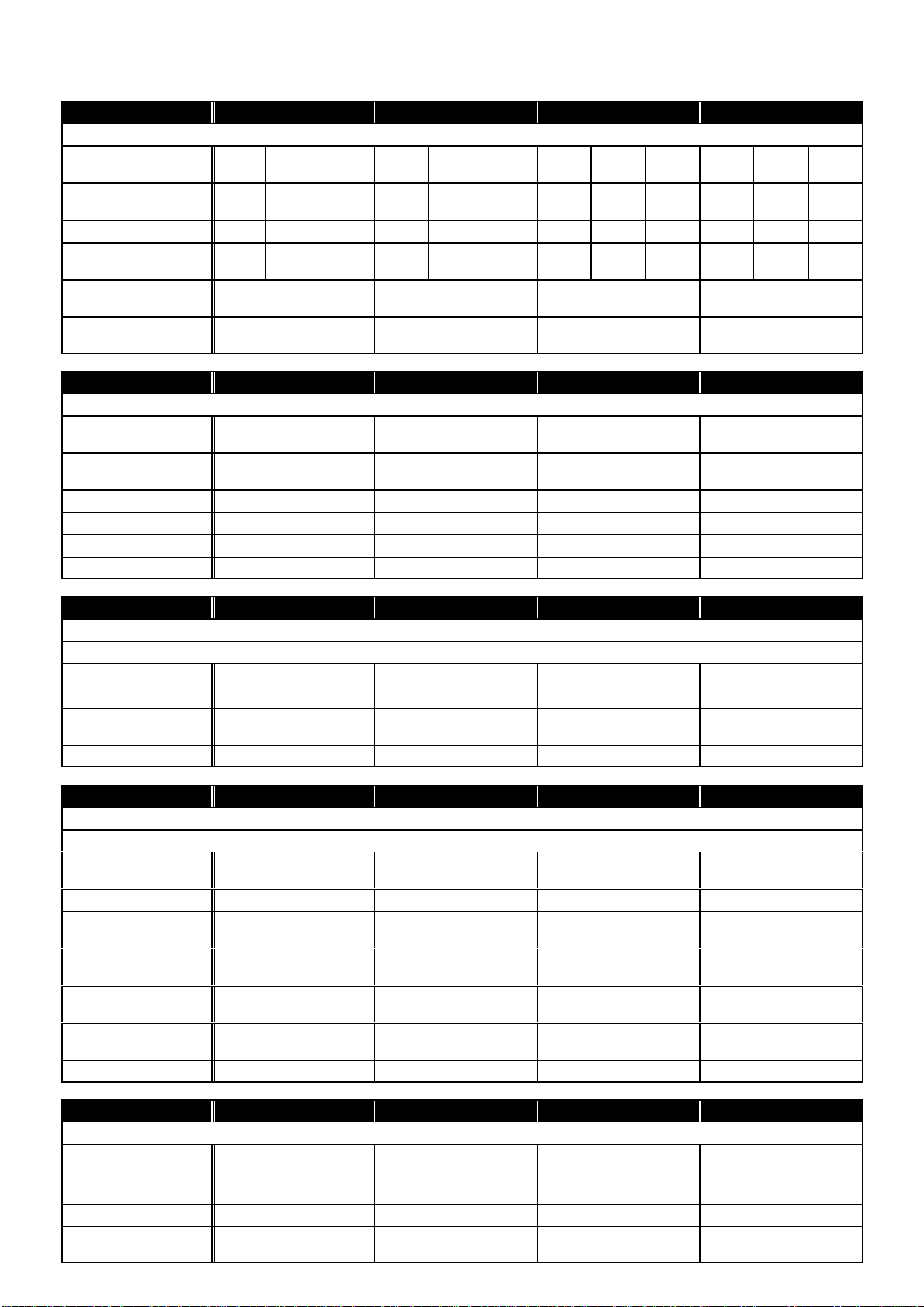
D60 D75 D100 102
COMPRESSOR
Maximum operating
pressure 8,0
bar 10,0
bar 13,0
bar 8,0
bar 10,0
bar 13,0
bar 8,0
bar 10,0
bar 13,0
bar 8,0
bar 10,0
bar 13,0
bar
Normal operating
pressure 7,8
bar 9,8
bar 12,8
bar 7,8
bar 9,8
bar 12,8
bar 7,8
bar 9,8
bar 12,8
bar 7,8
bar 9,8
bar 12,8
bar
Maximum Pressure ratio 9:1 11:1 13:1 9:1 11:1 13:1 9:1 11:1 13:1 9:1 11:1 13:1
Flow rate 7,16
m3/min 6,27
m3/min 5,20
m3/min 8,50
m3/min 7,45
m3/min 6,20
m3/min 11,60
m3/min 10,10
m3/min 8,50
m3/min 12,00
m3/min 11,90
m3/min m3/min
Maximum airend
discharge temperature 109C 109C 109C 109C
Ambient operating
temperature +2C →+40C +2C →+40C +2C →+40C +2C →+40C
D60 D75 D100 102
MOTOR
Nominal power 45kW 55kW 75kW 8bar = 75
10bar = 90
Maximum power (Class
‘F’ insulation) 49,5kW 60,5kW 82,5kW 8bar = 82,5kW
10bar = 99kW
Speed (IP23/55) 2940/2960 RPM 2940/2960 RPM 2940/2960 RPM 2940/2960 RPM
IP rating 23/55 23/55 23/55 23/55
Frame B3 / B5 B3 / B5 B3 / B5 B3 / B5
Insulation class F F F F
D60 D75 D100 102
COOLING SYSTEM
Air cooled
Cooling air flow 8100 m3/min 9700 m3/min 13400 m3/min 13400 m3/min
Maximum ∆P in air ducts 59 / 6 Pa/mm WG 59 / 6 Pa/mm WG 59 / 6 Pa/mm WG 59 / 6 Pa/mm WG
Heat to be dissipated 45kW 55kW 75kW 8 bar – 75kW
10 bar – 90kW
Compressed air outlet ∆T 8C – 12C 8C – 12C 8C – 12C 8C – 12C
D60 D75 D100 102
COOLING SYSTEM
Water cooled
Cooling water flow
∆T15/30K 2,6 / 1,3 m3/min 3,1 / 1,55 m3/min 4,4 / 2,2 m3/min 4,4 / 2,2 m3/min
Cooling water ∆P2 bar 2 bar 2 bar 2 bar
Cooling water inlet
temperature (min/max) 10C / 30C 10C / 30C 10C / 30C 10C / 30C
Cooling water outlet
temperature 45C 45C 45C 45C
Cooling water pressure
(min/max) 3 / 10 bar 3 / 10 bar 3 / 10 bar 3 / 10 bar
Compressed air outlet ∆T 8C – 12C 8C – 12C 8C – 12C 8C – 12C
Cooling water inlet/outlet R1 R1 R1 R1
D60 D75 D100 102
GENERAL DATA
Residual coolant content 1 – 3 mg/m31 – 3 mg/m31 – 3 mg/m31 – 3 mg/m3
Separator vessel
capacity 110 l110 l110 l110 l
Coolant capacity 73 l73 l77 l77 l
Sound pressure level to
CAGI–PNEUROP 71 dB(A) 75 dB(A) 77 dB(A) 76 dB(A)
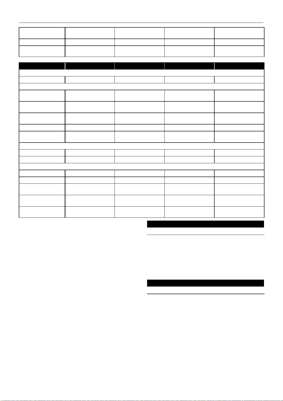
GENERAL INFORMATION
11
D60 D75
D100 D102
Weight (IP23/55) 990kg/1015kg 1025kg/1070kg 1160kg/1310kg 8bar = 1325kg/1475kg
10bar = 1460kg/1640kg
Discharge connection G2 G2 G2 G2
Dimensions (L x W x H) 1950mm x 1150mm x
1700mm 1950mm x 1150mm x
1700mm 1950mm x 1150mm x
1700mm 1950mm x 1150mm x
1700mm
D60 D75 D100 102
ELECTRICAL DATA
Standard voltage 3 ~ 400V 3 ~ 400V 3 ~ 400V 3 ~ 400V
Drive motor
Power 45kW 55kW 75kW 8 bar – 75
10 bar – 90
Full load current
(nominal) IP23/55 84A/80A 99A/96A 138A/128A 8 bar – 138A/128A
10 bar – 164A/150A
Starting current (approx.) 221A/232A 245A/290A 340A/434A 8 bar – 340A/434A
10 bar – 403A/440A
Starting time 3.5 S 3.5 S 3.5 S 3.5 S
Starts per hour 4
(IP23/54) 4
(IP23/54) 4
(IP23/54) 4
(IP23/54)
Fan motor
Power 1,5kW 1,5kW 1,5kW 1,5kW
Full load current 3,8A 3,8A 3,8A 3,8A
Control voltage
Star/delta combination 230 VAC 230 VAC 230 VAC 230 VAC
Control (ECOMATIC) 24 VDC 24 VDC 24 VDC 24 VDC
Control
(ECOCONTROL) 12 / 24 VDC 12 / 24 VDC 12 / 24 VDC 12 / 24 VDC
Mains supply cable
(cross section) 150 PVC/PVC 70 PVC/PVC 95 PVC/PVC 8 bar – 95 PVC/PVC
10 bar – 120 PVC/PVC
Fuse rating 2125A 160A 200A 8 bar – 200A
10 bar – 250A
1Local Regulations apply if stricter than above.
The voltage drop must not exceed 5% of the nominal voltage.
It may be necessary to use cables with a larger section than those
stated to comply with this requirement.
2gG
NOTE
All data applies to standard product only.
ECOCONTROL
KEY
E10 Power wiring
E11–13 Control wiring
E14 Options
E15 Layout of components
E16 Cable numbers
ECOMATIC
KEY
E20 Power wiring
E21–22 Control wiring
E14 Options
E23 Layout of components
E24 Cable numbers

GENERAL INFORMATION 12
D60 D75
D100 D102
ECOCONTROL
ECOCONTROL

GENERAL INFORMATION
13
D60 D75
D100 D102
ECOCONTROL
ECOCONTROL

GENERAL INFORMATION 14
D60 D75
D100 D102
ECOCONTROL
U MAX = 220V
I MAX = 8A
P MAX 24V=150 WATTS
ECOCONTROL

GENERAL INFORMATION
15
D60 D75
D100 D102
ECOCONTROL
KEY
STARTER
PE Terminal, earth
L1–L3 Mains terminals
CB1/2 Circuit breaker
CB3 Circuit breaker
K1M Main contactor
K2M Delta contactor
K3M Star contactor
M1 Main drive motor
M31 Fan motor
F20 Relay, thermal overload
F30 Relay, thermal overload
T1 Transformer 230V
PTC Thermistor protection
X1 Socket, 24 way
KEY
INSTRUMENTS
T2 Transformer 18V ECOCONTROL
T2 Transformer 18V/10V ECOMATIC
X1 Plug, 24 way
S10 Emergency stop
P24 Hourmeter (Total)
P25 Hourmeter (Load)
V1 Solenoid valve (Load)
Y5 Valve, coolant stop
X73 Block, terminal
S33 Air filter, vacuum switch
S34 Coolant filter, vacuum switch
S17 Switch, maximum pressure
S1 Switch, auto/continuous
S14.1 Gauge, temperature
A11 Indicator board (ECOCONTROL)
S35 Separator, vacuum switch
S40 Rotation, vacuum switch

GENERAL INFORMATION 16
D60 D75
D100 D102
KEY
A20 Circuit board ECOMATIC
A12 Circuit board (option)
A13 Circuit board(option)
A10 Circuit board ECOCONTROL
X71 Socket (cable loom machine)
NLZ Off load timer
S/H Starts per hour
GLW Sequencer connection
SO1 Button stop
SO2 Button start
SO3 Switch, Auto/Continuous
ECOMATIC
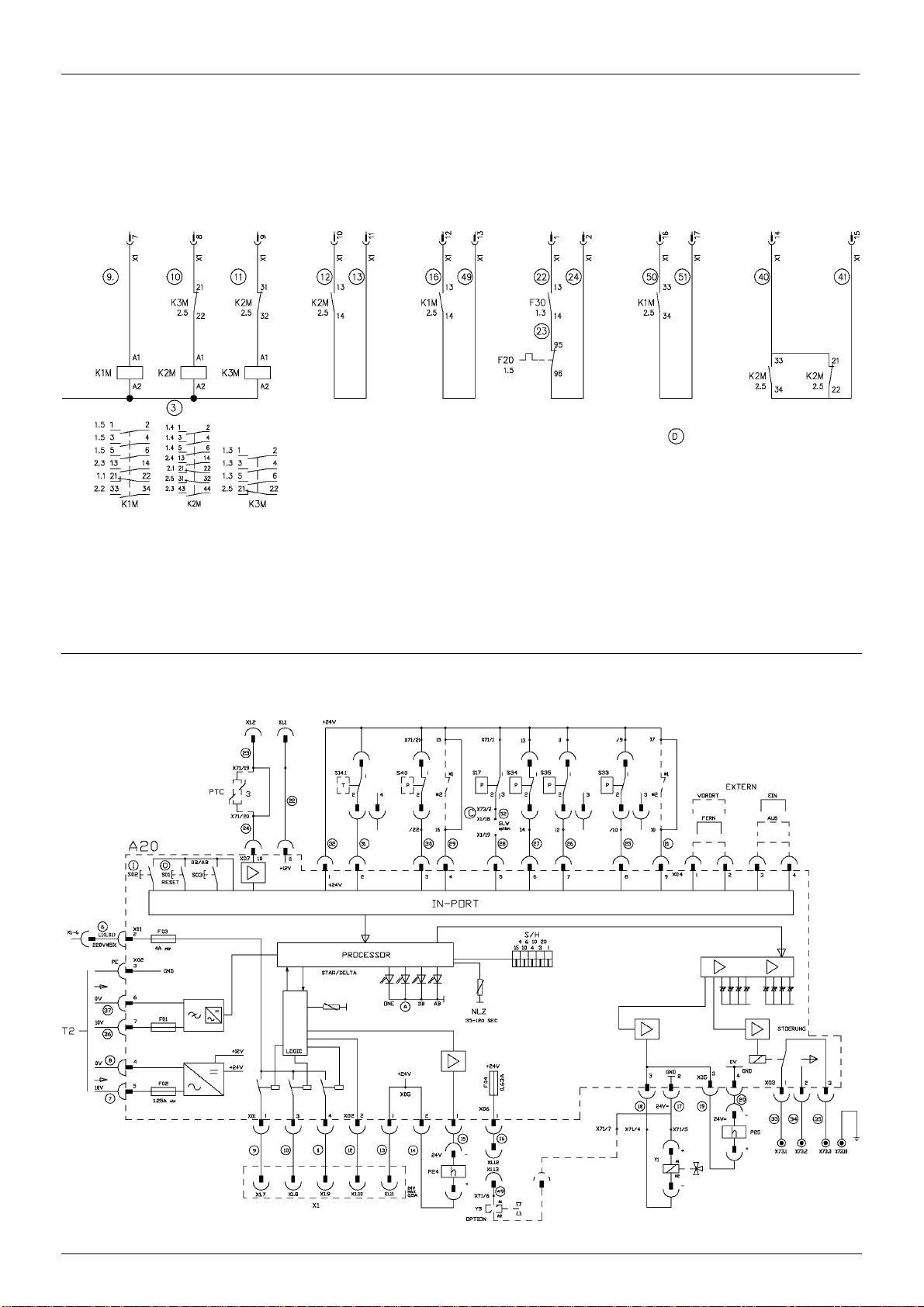
GENERAL INFORMATION
17
D60 D75
D100 D102
ECOMATIC
ECOMATIC
This manual suits for next models
3
Table of contents
Popular Air Compressor manuals by other brands


Craftsman
Craftsman 919.184190 owner's manual

Stanley
Stanley Fatmax FMXCMS2020TE Instruction manual for owner's use

King Canada
King Canada 8496K Service manual

Sears
Sears Craftsman 919.167463 owner's manual

Clarke
Clarke MONZA Operation & maintenance instructions

Eaton Compressor
Eaton Compressor POLAR AIR P01PSXXP10V120V208X user manual

Husky
Husky C041H Use and care guide

EINHELL
EINHELL TE-AC 430/90/10 Original operating instructions

VONROC
VONROC CR505DC Original instructions

Briggs & Stratton
Briggs & Stratton 74002 Operator's manual

Oshkosh Corporation
Oshkosh Corporation IMT CAS40P Installation, Operation, Maintenance & Parts Manual

Atlas Copco
Atlas Copco XAS 185 CDU T4 Original instructions