Eaton Compressor POLAR AIR P01PSXXP10V120V208X User manual

Polar Air Electric Operated, Piston Compressors
1

Operating Instructions
2
Polar Air designs and manufactures products for safe operation. However, operators and maintenance persons
are responsible for maintaining safety. All safety precautions are included to provide a guideline for minimizing
the possibility of accidents and property damage while equipment is in operation. Keep these instructions for
reference.
ELECTRIC OPERATED,
PISTON COMPRESSORS

Polar Air Electric Operated, Piston Compressors
3
Model PP05H080I1 PP07H080V1 PP10H120Y1 PP07H080V3 PP10H120Y3
Tank Type
Dimensions
Horizontal
76 x 30 x 56
Horizontal
76 x 30 x 56
Horizontal
78 x 32 x 50
Horizontal
76 x 30 x 56
Horizontal
78 x 32 x 50
Model PP05V080I1 PP07V080V1 PP10V120Y1 PP07V080V3 PP10V120Y3
Tank Type
Dimensions
Vertical
34 x 24 x 72
Vertical
34 x 24 x 72
Vertical
50 x 32 x 78
Vertical
34 x 24 x 72
Vertical
50 x 32 x 78
Tank Size 80 Gallon 80 Gallon 120 Gallon 80 Gallon 120 Gallon
Description 5HP
Single Phase
7.5HP
Single Phase
10HP
Single Phase
7.5HP
Three Phase
10HP
Three Phase
SCFM @ 175 psi 17.0 26.0 35.0 26.0 35.0
Max PSI 175 175 175 175 175
Motor HP 5HP 7.5HP 10HP 7.5HP 10HP
Motor RPM 1750 1750 1750 1750 1750
Voltage 208V/230V 208V/230V 208V/230V 208/230/460/575 208/230/460/575
Pump Model APP2I0524T APP4V1043T APP3Y1544T APP4V1043T APP3Y1544T
Pump RPM 650 640 600 640 600
Noise DB(A) 73 73 76 73 76
Outlet Connection NPT 3/4” NPT 3/4” NPT 1” NPT 3/4” NPT 1”
Weight (±5 lbs.) 715 958 1095 958 1095
Shipping Weight 800 1043 1242 1043 1242
Model Specication Charts . . . . . . . . . . . . .3-4
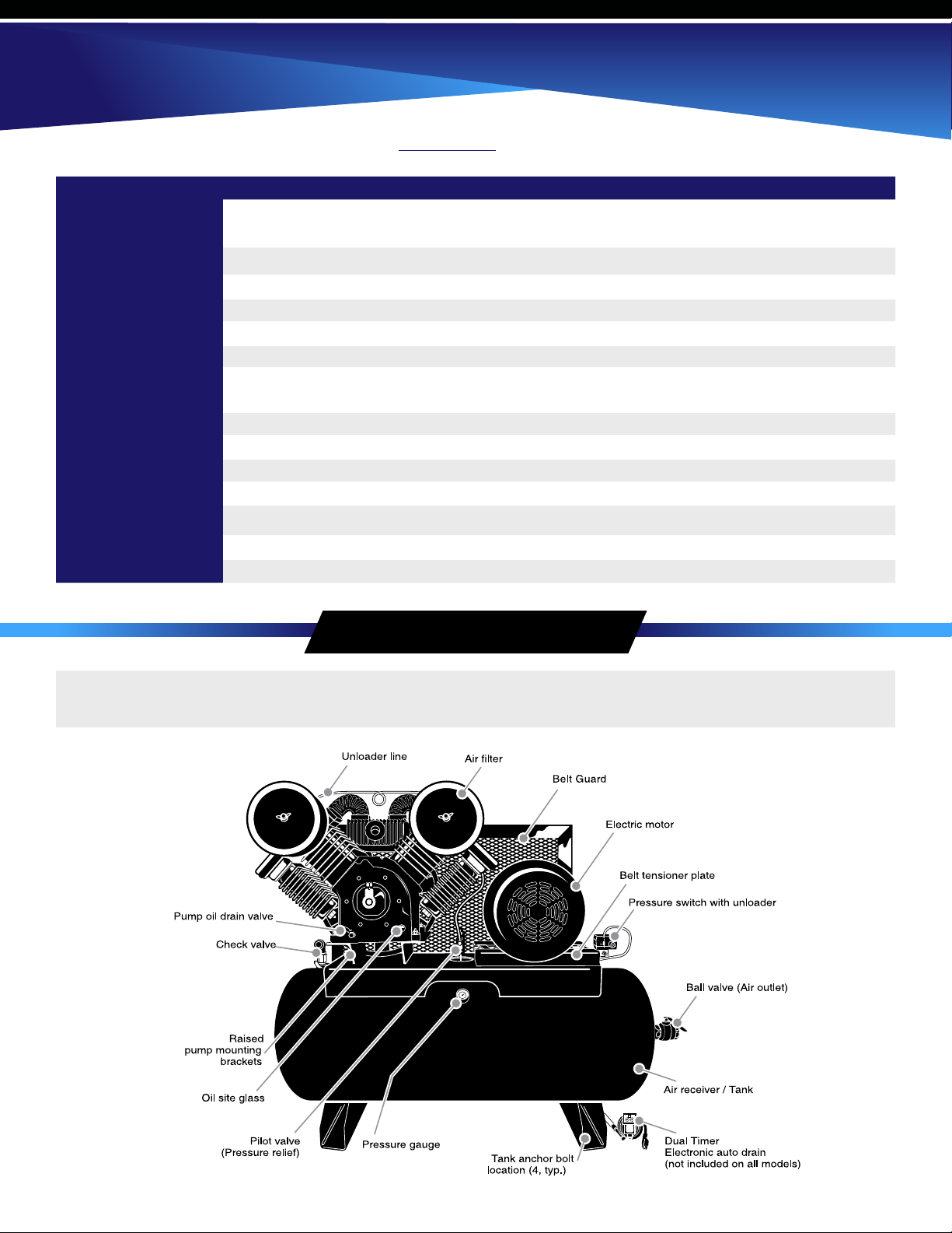
Description . . . . . . . . . . . . . . . . . . . . . . . . . 4
Safety Information . . . . . . . . . . . . . . . . . . . 5
TagDenitions....................5
BasicGuidelines.................5
BreathableAir....................6
PressurizedComponents..............6
PersonalProtectiveEquipment..........6
Inspection.........................6
ForkliftSafety.....................7
LiftingSafety......................7
Installation . . . . . . . . . . . . . . . . . . . . . . . . . 8
Area...........................8
PipingSafety.....................8
Piping/TankInstallation.............9
ElectronicAutoDrain(ifequipped)....10
ElectricalSafety...................11
WiringInstallation..................12
Operation..........................13
SafetyRules......................13
StartUp........................14
ContinuousRunFeature..........15
Maintenance........................15
SafetySteps......................15
BeltAdjustment..................16
ChangingOil.....................17
SafetyValve.....................17
Tank.......................17
Maintenance Schedule................18
Troubleshooting....................18
Warranty..........................19
Contents
Polar Air Electric Operated, Two-Stage, 5-10 Hp Piston Air Compressors
L•W•H
(inches)
L•W•H
(inches)

Operating Instructions
4
Model PP15V120Y3 PP15H120Y3 PP20H120V3 PP25H120V3
Description 15 Hp
Three Phase
15 Hp
Three Phase
20 Hp
Three Phase
25 Hp
Three Phase
SCFM @ 175 psi 52.0 52.0 68.0 89.0
Max PSI 175 175 175 175
Motor HP 15 Hp 15 Hp 20 Hp 25 Hp
Motor RPM 1750 1750 1750 1750
Voltage 208/230/460/575 208/230/460/575 208/230/460/575 208/230/460/575
Tank Size 120 Gallon
Vertical
120 Gallon
Horizontal
120 Gallon
Horizontal
120 Gallon
Horizontal
Pump Model APP3Y2062T APP3Y2062T APP4V2598T APP4V2598T
Pump RPM 640 640 640 740
Noise DB(A) 76 76 78 79
Outlet Connection NPT 1” NPT 1” NPT 1” NPT 2”
Dimensions 33 x 24 x 73 79 x 32 x 62 72 x 30 x 51 72 x 30 x 51
Weight (lbs.) 1410 1410 1500 1703
Shipping Weight 1512 1512 1609 1810
Polar Air Electric Operated, Two-Stage, 15-25 Hp Piston Air Compressors
Unit conguration and appearance varies by model.
Callouts are for general identication.
Description
L•W•H
(inches)

Polar Air Electric Operated, Piston Compressors
5
CALIFORNIA PROPOSITION 65
This manual contains very important information to know and understand. This is provided for SAFETY and to
PREVENT EQUIPMENT PROBLEMS. To help understand this information, observe the following:
This product or its power cord may contain chemicals known to the State of
California to cause cancer and birth defects or other reproductive harm. Wash
hands after handling.
1. Allow only trained, authorized persons who have read and understood these operating instructions to use
this compressor. Failure to follow the instructions, procedures and safety precautions in this manual can
result in accidents and injuries.
2. NEVER start or operate the compressor under unsafe conditions. Tag the compressor, disconnect and lock
out all power to it to prevent accidental start-up until the condition is corrected.
3. Install, use and operate the compressor only in full compliance with all pertinent OSHA regulations and all
applicable Federal, State & Local codes, standards and regulations.
4. NEVER modify the compressor and/or controls in any way.
5. Keep a rst aid kit in a convenient place. Seek medical assistance promptly in case of injury. Avoid infection
by caring for any small cuts and burns promptly.
Danger indicates an imminently hazardous situation which, if not avoided,
will result in death or serious injury.
Warning indicates a potentially hazardous situation which, if not avoided,
could result in death or serious injury.
Caution indicates a potentially hazardous situation which, if not avoided,
may result in minor or moderate injury.
Notice indicates important information, that if not followed, may
cause damage to equipment.
Read all manuals included with this product carefully. Be
thoroughly familiar with the controls and the proper use of the
equipment.
DANGER
WARNING
WARNING
CAUTION
NOTICE
Safety Information
Basic Guidelines

Operating Instructions
6
1. NEVER use air from this compressor for breathable air except in full compliance with OSHA
Standards 29 CFR 1910 and any other Federal, State or Local codes or regulations.
2. DO NOT use air line anti-icer systems in air lines supplying respirators or other equipment used to
produce breathable air. DO NOT discharge air from these systems in unventilated or other conned
areas.
Death or serious injury can result from inhaling compressed air
without using proper safety equipment. See OSHA standards on safety
equipments.
DANGER
This equipment is supplied with a ASME designed pressure vessel protected by an ASME rated relief valve. Pull the
ring before each use to make sure the valve is functional. Refer to gure 10. DO NOT attempt to open valve while the
machine is under pressure.
Be sure all operators and others around the compressor and its controls comply with all applicable OSHA, Federal,
State and Local regulations, codes and standards relating to personal protective equipment. This includes respiratory
protective equipment, protection for the extremities, protective clothing, protective shields and barriers, electrical
protective equipment, and personal hearing protective equipment.
A forklift may be necessary for unloading the Polar Air compressor. Use all forklift safety measures and require a
certied forklift operator. Refer to gure 1 for safe unloading procedure.
Make sure pallet-mounted compressors are rmly secured to the
pallet before moving. NEVER attempt to move a compressor that is not
secure as serious injury or property damage could occur.
Inspect compressor prior to any use. Check for external damage that
might have occurred during transit. Be careful of moving parts then test
pulley by turning it freely by hand. Report any damage to delivery carrier
immediately.
WARNING
CAUTION
Breathable Air
Pressurized Components
Personal Protective Equipment
Inspection

Polar Air Electric Operated, Piston Compressors
7
Do not operate unit if damaged during shipping, handling or use.
Damage may result in bursting and cause injury or property damage.
WARNING
1. Make sure lift operator stays aware while moving compressor.
2. Be sure load is secure and well balanced before moving the compressor.
3. Make sure forks are fully engaged and level before lifting or moving compressor.
4. Keep load as low as possible and observe safe operating practices.
1. Carefully inspect all lifting equipment and make sure it is in
good condition. Rated capacity should exceed compressor
weight. Make sure lifting hook has a functional safety latch
or equivalent and is properly attached to lifting feature.
2. Make sure lifting points are in good condition and tighten
any loose nuts or bolts before lifting.
3. Use provided lifting feature or appropriate sling. A sling must
be used when moving compressor with a helicopter or other
air borne equipment. Be sure to follow OSHA standards 29
CFR 1910 Subpart N.
4. Use guide ropes or equivalent to prevent twisting or
swinging of the compressor while it is in the air and NEVER attempt to lift in high winds. Keep compressor as
low to the ground as possible.
5. Keep persons away and make sure no one is under the compressor while it is lifted.
6. Only use lifting features provided for entire compressor package. NEVER use bolts or other hooks on
invididual components to move the compressor.
7. Make sure to put compressor on a level surface that can support the weight of the compressor and loading
equipment.
Forklift Safety
Lifting Safety

Operating Instructions
8
1. Install compressor in a clean, dry and well-lit area. Be sure installation area can maintain a temperature
range between 35˚ - 110˚ F.
2. Allow sufficient space around compressor for maintenance access and adequate airow. Mount unit with
pulley towards wall and leave a minimum of 15 inches of clearance.
3. Use shims to level compressor if installation area is not at. This will avoid excessive vibration
and premature pump wear.
4. If acid is used in operating environment or air is dust laden, pipe intake to outside, fresh air. Increase
pipe size by one size for every 20 feet of run. Be sure to install protective hood around intake lter.
5. In operating environments where excessive water, oil, dirt, acid or alkaline fumes are present, a TEFC
(totally enclosed, fan cooled) motor is recommended. Check nameplate for motor type.
6. Insulate cold water or other low temperature pipes that pass overhead to avoid condensation dripping on
compressor which could cause rust and / or motor shorting.
Safety Steps
1. Install appropriate ow-limiting valves as necessary according to pipe size(s) used and run lengths. This will
reduce pressure in case of hose failure, per OSHA Standard 29 CFR 1926.302(b)(7).
2. Flow-limiting valves are listed by pipe size and rated CFM. Select appropriate valves accordingly, in
accordance with the manufacturer’s recommendations.
If ambient temperature drops below 32˚F, be sure to protect safety/relief
valves and drain valves from freezing. NEVER operate compressor with
temperatures below 15˚F or above 125˚F.
CAUTION
DANGER
Installation
Area
Piping
DO NOT install compressor in boiler room, paint spray room, or area
where sandblasting occurs. Make sure inlet air is away from exhaust
fumes or other toxic, noxious or corrosive fumes or substances.

Polar Air Electric Operated, Piston Compressors
9
1. Place tank feet on 1/4” thick rubber pads. Thicker padding will increase vibration and the possibility of
cracking the tank or other unit damage. Do not place unit on dirt oor or uneven surface.
2. Fasten anchor bolts snugly but do not overtighten so normal vibration will not damage unit.
3. Use a exible connector between compressor tank and piping system to minimize noise, vibration, unit
damage, and pump wear.
4. Install appropriate ASME code safety valves and make sure piping system is equipped with adequate
condensate drains. See gure 2. Refer to gure 3 for recommended closed loop installation.
5. Make sure any tube, pipe or hose connected to the unit can withstand operating temperatures and retain
pressure.
6. Never use reducers in discharge piping. Keep all piping and ttings the same size in the piping system.
Never install a shut-off valve such as a glove or gate valve, between the
pump discharge and the air tank unless a safety valve is installed in
the line between valve and pump.
DANGER
Compressor unit is top heavy and must be bolted to solid, at surface
to avoid falling and premature pump wear. Splash lubrication will not
operate properly if unit is not level.
Never use plastic (PVC) pipe for compressed air. Serious injury or
death could result.
WARNING
WARNING
Piping / Tank Installation

Operating Instructions
10
Minimum Pipe Size For Compressed Air Lines
(Pipe size shown in inches)
Air Drop
(typ.)
PLAN VIEW
Closed loop system
in piping from air
supply to minimize
pressure drop and
two directions.
From Compressor
Water trap
with drain
Air Drop:
to minimize condensation in air drop
ELEVATION
From
Compressor
To Air Tool
7. For permanent installations of compressed air systems, determine total length of system and select correct
pipe size. Make sure underground lines are buried below frost line and avoid areas where condensation
could build up and freeze.
8. Test entire piping system before underground lines are buried. Be sure to nd and repair all leaks before
using compressor.
One auto drain can be used for multiple compressor units. Install necessary piping with appropriate ttings.
Never exceed recommended pressure or speed while operating
compressor.
WARNING
Electronic Auto Drain (if equipped)

Polar Air Electric Operated, Piston Compressors
11
1. Plug auto drain into 120V outlet.
2. Set timers to desired settings. See gure 4. If drain is used for multiple units, increase timer settings as
needed.
3. Use test button to check proper operation. Refer to maintenance section for proper care.
1. Follow all NEC and local codes for electrical wiring. Allow only authorized Polar Air service person or
certied electrician to install electrical components.
2. Put unit on dedicated circuit and make sure no other electrical equipment is wired into it. Failure to wire
unit on independent circuit can cause circuit overload and/or imbalance in motor phasing. Install proper No
Fuse Breaker (NFB) according to kW output of compressor.
3. Ensure incoming service has adequate ampere rating.
4. Ensure supply line has the same electrical characteristics (voltage, cycles and phase) as the electric motor.
5. Refer to amp load information on motor tag and use correctly sized wiring. Be sure to consider distance
between power supply and machine.
6. Install surge protection device between power supply and compressor motor.
7. Make sure to install properly sized breakers and fuses.
8. The unit must be properly grounded. DO NOT connect ground wire to air or cooling lines.
Be sure only trained and authorized personnel install and maintain this
compressor in accordance with all applicable federal, state and local
codes, standards and regulations. Follow all NEC (National Electric
Code) standards especially those concerning equipment grounding
conductors.
DANGER
Electronic Safety

Operating Instructions
12
9. Make sure proper overload protection for the motor is installed.
1. Connect rst power lead to 1L1.
2. Connect second power lead to 3L2.
3. Connect ground wire to existing motor ground wire.
1. Connect rst power lead to 1L1. Leave existing jumper
wire installed. See Figure 6.
2. Connect second power lead to 3L2. Leave existing
jumper wire installed.
3. Connect ground wire to ground lug.
4. Ensure all wiring and terminals are properly tightened.
Install power leads into terminals opposite motor wires.
Ensure power supply and internal wiring is adequate according to voltage and frequency stated on motor nameplate
and starter. Voltage should not vary more than 12% to ensure proper operation of compressor.
DANGER
Improperly grounded electrical components are shock hazards. Make
sure all the components are properly grounded to prevent death or
serious injury.
When wiring unit with magnetic starter, do not install power directly to
pressure switch to avoid possible re and property damage.
Single Phase Motors - No Magnetic Starter
Single Phase Motors - With Magnetic Starter
WARNING
N O
N
P
R
O
Q
S
Wiring Installation

Polar Air Electric Operated, Piston Compressors
13
1. Connect rst power lead to 1L1.
2. Connect second power lead to 3L2.
3. Connect third power lead to 5L3.
4. Connect ground wire to existing motor ground wire.
5. Check for proper motor rotation. When facing motor shaft, pulley should turn counterclockwise. If rotation is
reversed, turn off power then switch two power leads.
1. Make sure all operators receive product training, read and understand all instructions.
Three Phase Motors (See gure 7)
WARNING
Ensure wiring is installed according to voltage required for proper
motor operation (220V or 460V).
Keep all ammable, combustible, poisonous and noxious materials
away from operating area. Make sure there are no oily rags, trash,
leaves, litter or other combustible materials in operating area. Keep
suitable, fully charged re extinguishers nearby when servicing and
operating the compressor.
CAUTION
Safety Rules
Operation

Operating Instructions
14
2. NEVER allow modications to compressor structure or controls.
3. Keep all ignition sources away from exposed electrical parts.
4. Keep all persons clear of compressor during start-up and operation.
5. NEVER operate the compressor with the fan, coupling or other guards removed.
6. DO NOT engage in horseplay with air hoses as death or serious injury may result.
7. Make sure to provide adequate ventilation and use proper lubricant while operating the compressor. If
lubricant or other combustible substances are spilled, clean up immediately.
8. When checking or adding lubricant or when relling air line anti-icer systems with antifreeze compound, shut
off compressor and allow it to cool. Keep sparks, ames and other ignition sources away and DO NOT permit
smoking in the vicinity.
9. Stop compressor and disconnect power if a hazardous condition arises.
10. Wear snug tting clothing and conne long hair when around compressor. Keep all body parts and clothing
away from couplings, ywheel and other moving parts of the equipment.
11. DO NOT use air tools that are rated below the maximum rating of the compressor. Select air tools, air hoses,
pipes, valves, lters and other ttings accordingly. DO NOT exceed manufacturer’s rated safe operating
pressures for these items.
12. Make sure all hose connections are adequately secured to prevent tools or hose ends from being
accidentally disconnected.
1. This unit is shipped with pump break-in oil and should be ready to operate. Be sure to check for proper oil
level before operating the compressor. Oil should be in center of site glass. See gure 8.
2. Check for proper belt tension. There should be 1/2 inch slack. Refer to maintenance section if adjustment is
necessary.
Keep all persons away from the discharge opening of hoses or tools or
other points of compressed air discharge. If the machine is installed in
an enclosed area, be sure to vent the relief valve outside of the structure
or to an unoccupied area.
DANGER
NOTICE Use only Airbase Industries oil (PN: APOL03000G1). Use of any other
product will cause product damage and void the warranty.
Start-Up

Polar Air Electric Operated, Piston Compressors
15
3. Lightly push power switch to make sure system is working.
4. If motor shaft is not turning counter clock-wise,
disconnect power to terminal block then exchange
any two of the three power leads. Re-check rotation.
For heavy use applications such as sandblasting, the continuous run feature is available. This feature keeps main
feed line open to eliminate numerous motor starts/stops and to help cool pump.
To engage continuous run feature, open ball valve found by following copper tubing across cylinder heads to tank.
See gure 9.
Stop continuous run feature by closing valve so compressor will start and stop according to pressure switch.
Always make sure main power is off before touching belts or other
moving parts of compressor.
WARNING
Figure 9: Continuous run feature
Disconnect, tag and lock out power source then release all pressure
from the system before attempting to install, service, relocate or
perform ANY maintenance.
WARNING
1. Make sure repairs are done in a clean, dry, well lighted and ventilated area.
2. When cleaning, use air pressure less than 30 PSIG (2.1bar). NEVER use ammable solvents for cleaning
purposes. Also use effective chip guarding and personal protective equipment per OSHA standard 29 CFR
1910.242 (b).
Safety Steps
Continuous Run Feature (if equipped)
Maintenance

Operating Instructions
16
3. Relieve all internal pressure prior to opening any line, tting, hose, valve, drain plug, connection or other
component, such as lters and line oilers, and before relling optional air line anti-icer systems with
antifreeze compound.
4. Keep electrical wiring, including all terminals and pressure connectors in good condition. Replace any wiring
that has cracked, cut, or otherwise damaged insulation. Replace terminals that are worn, discolored or
corroded. Keep all terminals and pressure connectors clean and tight.
5. Keep all body parts and any hand-held tools or other conductive objects away from exposed live parts of the
electrical system. When making repairs or adjustments, stand on a dry, insulated surface and DO NOT contact
any other portion of the compressor.
6. DO NOT leave compressor unattended with exposed electrical components. Be sure to tag and disconnect all
power if temporary absence is necessary.
1. Proper belt tension is determined by pressing on belt midway
between motor pulley and ywheel. There should
be approximately 1/2 inch of deection.
2. Adjust belt tension as needed by loosening the four motor frame
nuts then adjusting single bolt head on belt tensioner. See gure
11. Remember to tighten motor bolts after adjustment is
made.
3. Always replace all belts with the same brand, at the same time.
Make sure belts are unimatched. Do not replace belts
independently.
CAUTION
Compressor components can become hot during operation. Avoid
bodily contact with hot liquids, hot surfaces and sharp edges and
corners.
Be sure to relieve all system pressure then lock out power and
tag compressor to prevent unexpected movement of the unit.
Inspect belt tension after rst 30 hours of operation then every 30 days.
WARNING
Belt Adjustment

Polar Air Electric Operated, Piston Compressors
17
Drain daily.
If unit is equipped with electronic auto drain:
1. Check daily to ensure proper operation.
2. Clean lter daily. Refer to gure 13.
4. Do not splash lubricating oil on belts or pulleys when adjusting or replacing belts.
All units are shipped with break-in oil. Change oil within rst 50 hours or 30 days of operation, whichever comes rst.
DO NOT use automotive type oil.
Change oil every 90 days or if oil becomes milky.
Check proper operation of safety valve before each use. Refer to gure 12. If valve does not open manually, replace
immediately. Discharge pressure is generally set at 175 PSI (12.1 bar). DO NOT attempt to open valve while
machine is under pressure.
NOTICE Use only Airbase Industries Oil (PN: APOL03000G1). Use of any other
product will cause product damage and void the warranty.
NEVER attempt to regulate or tamper with safety valve. Valve is sealed
and certied by ASME code and is designed to relieve system pressure
when necessary.
DANGER
Safety Valve
Tank
Changing Oil

Operating Instructions
18
Problem Possible Causes Resolutions
Low air pressure
Overheating
1. Clogged inlet lter
2. Air leak(s) in system
3. Application exceeds rated air output of
compressor
4. Cylinder head valves not sealing
5. Insufficient power
1. Duty cycle exceeded
2. Improper rotation
3. Head valve(s) not seating properly
4. Blown cylinder head gasket(s)
5. Restriction in head, intercooler or check
valve
6. Low oil
7. Dirt in intercooler ns or cylinder ns
8. Poor ventilation / ambient temperature too
high
1. Disassemble valve, clean thorougly
2. Use soapy water to locate leaks, replace or
tighten threaded parts
3. Check CFM requirements, change tool or use
compressor with higher air output
4. Remove valves from cylinder head, repair or
replace as necessary
5. Check power supply, rewire as necessary
1. Keep duty cycle at 60/40 to maintain pump life
2. When facing ywheel, ensure
counterclockwise rotation
3. Clean or replace
4. Replace gasket(s)
5. Clear blockage
6. Add oil. Ensure oil level is at middle of site
glass. See gure 8.
7. Use low pressure air to blow dirt away from
compressor
8. Increase ventilation around operating area.
Ensure compressor has adequate clear
space from walls and other possible
obstructions Ambient temperature should not
exceed 110˚ F.
Use only Airbase Industries Oil
(PN:APOL03000G1). Use of any
other product will cause product
damage and void the warranty.
NOTICE
Troubleshooting Chart
Maintenance Schedule

Polar Air Electric Operated, Piston Compressors
19
Parts used for warranty purposes must be supplied by Eaton Compressor and Fabrication Co., Inc. Warranty work will be performed by an approved Eaton Compres-
sor and Fabrication Co., Inc. Technician. If any maintenance (other than routine maintenance) is performed by a non-approved Eaton Compressor and Fabrication
Co., Inc. Technician, written pre-approval must be obtained from Eaton Compressor and Fabrication Co., Inc. to prevent voiding this Warranty. Failure to fully
comply with this warranty and fully comply with the manual herein will void this warranty.
All warranties are nontransferable.
The Oil Purchase Program is effective as of January 1, 2011.
EATON COMPRESSOR AND FABRICATION CO., INC. (and each of its subsidiaries, including POLAR AIR COMPRESSORS, INC.) makes the following Warranties:
1.
2.
3.
THAT EACH BARE COMPRESSOR PUMP UNIT TO BE FREE FROM DEFECTS IN MATERIAL, WORKMANSHIP, AND PARTS FOR 5 YEARS FOR THE UNIT FROM THE
DATE OF PURCHASE. Eaton Compressor and Fabrication Co., Inc. (and each of its subsidiaries) is not responsible for downtime during warranty service. If downtime
is necessary, it is the Purchaser’s discretion and obligation (at Purchaser’s expense) to have a redundant UNIT. Warranty repairs shall not include freight costs.
Purchaser is responsible for returning unit to Eaton Compressor and Fabrication Co., Inc. This pump must have Eaton Compressor and Fabrication Co., Inc. lubricant
Synthetic exclusively, the same which must be purchased from Eaton Compressor and Fabrication Co., Inc. (Mixing different brands of oils will void the pump
warranty). A service kit must be purchased from Eaton Compressor and Fabrication Co., Inc. for this warranty to apply. Service kits contain an air filter and synthetic
oil that must be changed annually. Annual proof of purchase of all oil programs must be maintained by the original purchaser of the compressor pump. If the unit
runs out of oil, this warranty is void. Failure to fully comply with this warranty and fully comply with the manual herein will void this warranty.
Exclusions include: service such as OIL CHANGES, FILTER REPLACEMENTS, GASKET TIGHTENING TO CORRECT OIL SEEPAGE or DRIVE BELT TIGHTENING and
VALVE CLEANING and are not covered under warranty.
Warranty shall be void under the following conditions: Failure to routinely change oil and to maintain a clean filter, or exceeding 70% duty cycle resulting in
overheating and excessive wear and tear, or exposing electrical components to rain or water, or installing the unit in a hostile environment such as acid vapors or
any caustic or abrasive matter that may be ingested into the pump, or installing the unit in an enclosed area where lack of cooling ventilation is present, such as in
boiler or equipment rooms where the ambient air exceeds 100˚F.
THAT EACH COMPRESSOR UNIT TO BE FREE FROM DEFECTS IN MATERIAL, WORKMANSHIP, AND PARTS FOR 5 YEARS FOR THE COMPRESSOR PUMP AND 2
YEARS ON THE REMAINDER OF THE UNIT FROM THE DATE OF PURCHASE. The UNIT also carries a 1-year labor warranty. Eaton Compressor and Fabrication Co.,
Inc. (and each of its subsidiaries) is not responsible for downtime during warranty service. If downtime is necessary, it is the Purchaser’s discretion and obligation
(at Purchaser’s expense) to have a redundant compressor. Warranty repairs shall not include freight costs. Purchaser is responsible for returning unit to Eaton
Compressor and Fabrication Co., Inc. This pump MUST have Eaton Compressor and Fabrication Co., Inc. Lubricant Synthetic exclusively, the same which must
be purchased from Eaton Compressor and Fabrication Co., Inc. (Mixing different brands of oil will void this warranty). A service kit must be purchased from Eaton
Compressor and Fabrication Co., Inc. for this warranty to apply. Service kits contain an air filter and synthetic oil that must be changed annually. Annual proof of
purchase of all oil programs must be maintained by the original purchaser of the compressor unit. If the unit runs out of oil, this warranty is void. Failure to fully
comply with this warranty and fully comply with the manual herein will void this warranty.
Exclusions include: service such as OIL CHANGES, FILTER REPLACEMENTS, GASKET TIGHTENING TO CORRECT OIL SEEPAGE or DRIVE BELT TIGHTENING and
VALVE CLEANING and are not covered under warranty.
Warranty shall be void under the following conditions: Failure to routinely change oil and to maintain a clean filter, or exceeding 70% duty cycle resulting in
overheating and excessive wear and tear, or exposing electrical components to rain or water, or installing the unit in a hostile environment such as acid vapors or
any caustic or abrasive matter that may be ingested into the pump, or installing the unit in an enclosed area where lack of cooling ventilation is present, such as in
boiler or equipment rooms where the ambient air exceeds 100˚F.
GENERAL PROVISIONS: Eaton Compressor and Fabrication Co., Inc. (and each of its subsidiaries) is not responsible for downtime during warranty service. If
downtime is necessary, it is the Purchaser’s discretion and obligation (at Purchaser’s expense) to have a redundant compressor. Warranty repairs shall not include
freight costs. If necessary, the Purchaser is responsible for returning unit and/or applicable part(s) to Eaton Compressor and Fabrication Co., Inc.
Exclusions include: service such as OIL CHANGES, FILTER REPLACEMENTS, GASKET TIGHTENING TO CORRECT OIL SEEPAGE or DRIVE BELT TIGHTENING and
VALVE CLEANING and are not covered under warranty.
Further exclusions include failure to fully and completely follow the guidelines set forth in the manual. Of specific note is where a product is used where granite and/
or concrete work is performed or conditions are dusty and the product is required to be housed in a separate room from the adverse conditions where the product
has access to fresh air intake.
Warranty Statement

Splash Lubricated, Air Compressor Pumps
SPLASH LUBRICATED
AIR COMPRESSOR PUMPS
Airbase Industries designs and manufactures products for safe operation. However, operators and maintenance
persons are responsibile for maintaining safety. All safety precautions are included to provide a guideline for
minimizing the possibility of accidents and property damage while equipment is in operation.
Keep these instructions for reference.
AMNU000001 0810
Operating Instructions
Model Specication Charts . . . . . . . . . . .2
Safety Information . . . . . . . . . . . . . . . . . . . 3
TagDenitions..................3
BasicGuidelines................3
Breathable Air . . . . . . . . . . . . . . . . 3
PersonalProtectiveEquipment......4
Inspection . . . . . . . . . . . . . . . . . . . . . . . . . 4
Installation . . . . . . . . . . . . . . . . . . . . . . . . 4
Area. . . . . . ............. . . . . 4
PipingSafetySteps.............5
Tank Installation . . . . . . . . . . . . . 5
Pump Installation. . . . . . . . . . . . 5
Operation . . . . . .. . . . . . . . . . . . . . . . .8
SafetyRules....................8
StartUp......................9
Maintenance........................9
SafetySteps.....................9
BeltAdjustment....................10
ChangingOil......................10
Maintenance Schedule.................11
Troubleshooting......................11
Warranty..............................12
Contents
This manual suits for next models
22
Table of contents
Other Eaton Compressor Air Compressor manuals

Eaton Compressor
Eaton Compressor POLAR AIR PP20H240V3 User manual

Eaton Compressor
Eaton Compressor POLAR AIR PP05H080I1 User manual

Eaton Compressor
Eaton Compressor POLAR AIR P01IXXXP07V080VXXXX User manual

Eaton Compressor
Eaton Compressor Polar Air PRS0050001 User manual

Eaton Compressor
Eaton Compressor POLAR AIR P01PSXXP07V120V208X User manual
Popular Air Compressor manuals by other brands

Metabo
Metabo Power 160-5 18 LTX BL OF Original instructions

DV Systems
DV Systems G20 Installation and start-up data

L&W Compressors
L&W Compressors LW 300 D MC operating instructions

Craftsman
Craftsman 919.16644 owner's manual

AirMan
AirMan PDS390S-4B1 instruction manual

King Canada
King Canada 8439 Service manual