ECOGENICA EG-330FR User manual

Congratulations
on making the smart decision:
EG-330FR
EG-290FR
EG-260FR
EG-215FR
HEAT PUMP WATER HEATER
PRODUCT & INSTALLATION GUIDE
SAVINGS REBATE ENVIRONMENT

2ECOGENICA FR MODELS PRODUCT & INSTALLATION GUIDE
About the Ecogencia FR Range
Designed and developed in Australia for Australian conditions,
the Ecogenica range of direct heat transfer water pump heaters offers
ground-breaking technology to deliver energy efficient hot water savings
to Australian homes and businesses.
FEATURES
• Australia’s most energy efficient Hot Water Heat Pump -up to 80% energy savings
• Powerful Heat Pump -fast hot water production = lots of hot water at a lower price
• Direct heat transfer condenser tank -greater reliability & less maintenance
• Easy to install
• Slim line tank design- fits into narrow areas
The Technical bit
The Ecogenica 215FR, 260FR, 290FR and 330FR models are fully dedicated, quick connect heat pumps
using the most advanced reverse cycle heating technology which directly heats the water instead of the air,
like other traditional gas or electric hot water pumps.
Our range of heat pumps have a large surface area and don’t
need a heat element instead extracting heat from the air
- even if it’s freezing outside. They utilise cold R290, a natural
refrigerant, which absorbs heat energy as it passes through
the large heat pump fin coil. As the gas passes through the
fin coil, heat from the air turns the cold low pressure R290
vapour into a high-pressure gas, which then passes through
a high efficiency rotary compressor, becoming super-heated.
The super-heated gas passes through the heat jacket which
is wrapped around the water cylinder and, once the gas loses
heat energy to the water, it reverts back to a cold vapour and
the cycle continues until the water is piping hot.
The tank will heat up between 1 and 4 hours in all weathers.
The compressor compresses the gas, just like a bicycle pump
(if you put your finger on it), and, like the bicycle pump, the gas
gets hot. This means the jacket never encounters the water,
and the direct heating process is more reliable and efficient
than other heating technologies.
With fewer moving parts - no circulation pumps
or troublesome heat exchangers - maintenance
is required less often , making the FR model range
a more reliable and resilient design compared
to other heat pump water heaters.
The coefficient of performance (COP)
of 4.8 means that for every 1kW of
power used from the power grid
(or from your solar power system)
the FR range of heat pumps puts in
4.8kW of effective power into your water.

3ECOGENICA FR MODELS PRODUCT & INSTALLATION GUIDE
Index
Reference Performance & Specifcations Page 4
Warnings Notice to Customer Page 5
Safety Information Page 6
1 Before Installation For all Models Page 7
2 System Debugging For all Models Page 8
SPLIT QUICK CONNECTION MODELS: 215FR/290FR/330FR Page 9
3 Components and Connections Page 10
4 Wiring Diagram Page 11
5 Installation Page 12-15
6 System Operation Page 16-17
7 System Troubleshooting Page 18-20
ALL-IN-ONE CONNECTION MODELS: 2600FR Page 21
8 Connections Page 22
9 Wiring Diagram Page 23
10 Installation Page 24-26
11 System Operation Page 27
12 System Troubleshooting Page 28
13 System Maintenance For all Models Page 29-30
14 Warranty For all Models Page 31

4ECOGENICA FR MODELS PRODUCT & INSTALLATION GUIDE
Reference: Performance & Specifications
Performance of the FR Models Easily compare features to choose the right model for you.
Specifications of the FR Models
Model 330FR 290FR 260FR 215FR
Energy Saving 75.6 % 80.1 % 74.7 % 79.0 %
No of People suitable for 5-9 4-7 3-6 1-5
Model 330FR 290FR 260FR 215FR
Tank Volume 330 L 290 L 260 L 215 L
Input Power 1020 W 750 W 670 W 630 W
Heating Capacity 4600 W 3750 W 3250 W 3150 W
COP 4.51 W/W 5.0W/W 4.85 W/W 5.0 W/W
Recovery Rate 20/55* 98.9 80.6 69.8 67.7
Fittings 20mm / G 3/4 20mm / G 3/4 20mm / G 3/4 20mm / G 3/4
Sound Levels 50 47 50 47
Tank Size Height 1815 mm 1850mm 2115 mm 1815 mm
Width 620 mm 570 mm 600 mm 510 mm
Heat Pump Size Height 610 mm 545 mm Built 545 mm
Width 840 mm 780 mm onto 780 mm
Depth 313 mm 276 mm Tank 276 mm
Max Current 7.0 A 5.0 A 5.0 A 4.5 A
Power Supply 220-240V/50Hz 220-240V/50Hz 220-240V/50Hz 220-240V/50Hz
Operating Temperature Range -7ºC ~+43ºC -7ºC ~+43ºC -7ºC ~+43ºC -7ºC ~+43ºC
Refrigerant Type R290 R290 R290 R290
Protection Ranking Class IPX4 IPX4 IPX4 IPX4
Configuration Split Quick Split Quick All-in-one Split Quick
Connection Connection Connection Connection
All results supplied by the independent test laboratory Intertek.
Test Conditions:
1. Default setting +55ºC
2. Outlet Water Temperature +55ºC
Inlet Water Temperature +14ºC
Dry Bulb Temperature +19ºC
Wet Bulb Temperature +15ºC
COMMERCIAL MODELS are available. 215FRC and 290FRC.
Parameters are the same as above. Commercial models have a higher set temperature.
The commercial models only need the top sensor installed. Please contact us for details on commercial installations.
* Recovery rate is 40 degrees temperature rise / 20 degrees ambient / 55 degrees water
temperature. Recovery rates at 6 degrees are approx 35% less than nominal recovery rates.
NOTES:
• 215FR, 290FR and 330FR models are split and come with Pre-Charged One Shot
Couplings for ease of installation by a plumber.
• Split Quick Connection models (215FR / 290FR / 330FR) only require standard
plumbing connections, heat pump is located on top of tank.
• All models use R290 natural refrigerant (propane), Plumbers require a gas fitters
license to handle Split Quick Connection models (215FR / 290FR / 330FR).
• All temperature is measured in degrees Celsius.

5ECOGENICA FR MODELS PRODUCT & INSTALLATION GUIDE
Warning: Safety Information
Please read all manuals carefully before installing and operating this unit.
The following safety warnings are very important, always read and obey all safety signs.
WARNING
• The device must be effectively grounded.
• RCBO circuit breaker must be installed.
• Do not remove, cover or damage any permanent
instructions or labels from the exterior or interior of the
unit panel.
• Only qualified personnel should install in accordance
with local and national regulations and this guide.
• Improper installation may cause water leakage, electric
shock or fire alarm.
• All electrical connections must comply with the
requirements of the local power company, the local
power company and this guide.
• Do not use rated fuse, otherwise it may malfunction and
cause electrical fire.
• Do not insert fingers, rods or other objects into the air
inlet or outlet. The fan is rotating at high speed, which
may cause injury.
• Do not use flammable sprays, such as hairspray or
paint, near the machine to avoid fire.
• Disposal: Do not dispose of electrical appliances as
unsorted municipal waste, A separate
collection facility should be used. Contact
your local government to find out information
about the collection system. If electrical
appliances are disposed of in landfills or
dump sites, hazardous substances
can seep into groundwater and cause health problems.
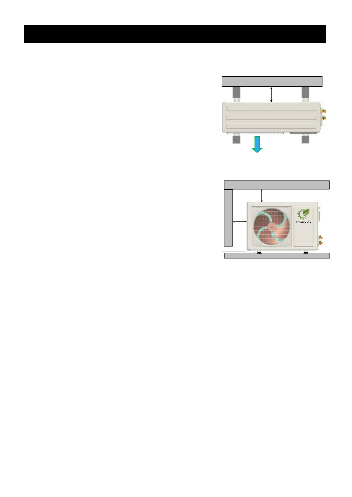
• The unit must be fixed firmly, otherwise noise and
vibration may be generated.
• Make sure there are no obstacles around the device.
• In places with strong wind (such as seaside areas),
the unit should be installed in a windproof place.
• The PTR valve should be operated every 6 months to
ensure that the valve does not have any restrictions.
The drain pipe should be well insulated to prevent the
water in the pipe from freezing in cold weather.
CAUTIONS
• The ground electrode must be well grounded.
Make sure all electrical sockets and plugs are
dry and tightly connected;
• Before cleaning, be sure to stop operation and
isolate the unit (ie, turn off the isolating switch
or circuit breaker). Otherwise, electric shock and
injury may occur;
• Water temperature over
50 degrees Celsius will cause
severe burns and even death.
Children, the disabled and the
elderly are at the highest risk
of burns. In the bath feel the
water temperature with your
hands before showering to avoid burns.
• Do not operate the machine with wet hands to
avoid electric shock.
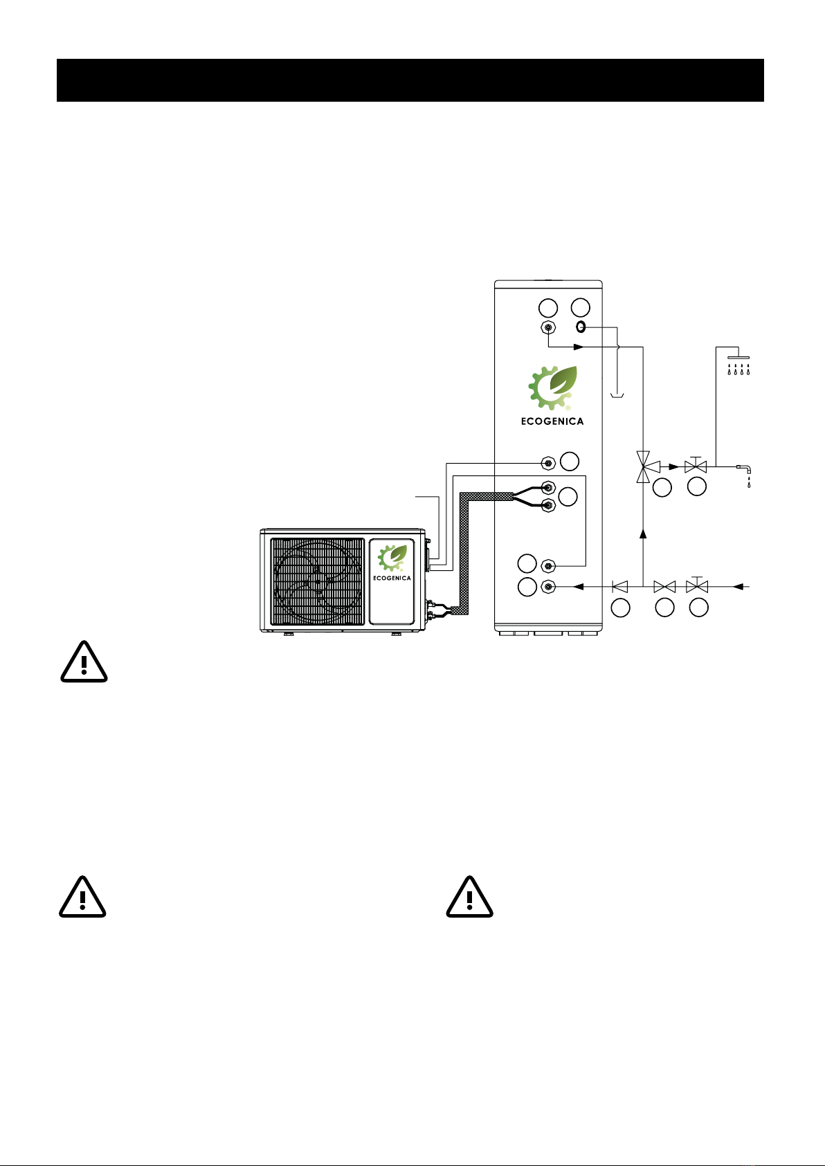
• A one-way check valve and a suitable isolation
valve must be installed on the water inlet side.
• It is normal for the one-way safety valve to
release some water during operation.
However, if there is a large amount of water,
please contact our service team. Improper
drainage can cause water damage to
surrounding areas such as buildings, furniture
etc. Except for repair and maintenance purposes,
do not turn off the power, especially in cold
weather, as it may freeze the machine when
the power is turned off. Continuously powered
heating water is necessary.

6ECOGENICA FR MODELS PRODUCT & INSTALLATION GUIDE
This unit requires
reliable earthing
before use,
otherwise
this may
result in
injury or death.
Warning: Notice to Customer
ť
This air source water heater must be installed and maintained by
licensed professionals in accordance with building regulations.
Only licensed professionals will issue you a certificate of compliance
certifying that the work in question meets all relevant standards,
and only licensed professionals will take out craft insurance.
The installation conforms to the Plumbing Code of Australia (PCA).
Do not install this if you cannot ensure that the power supply to the property is
properly grounded. The device must be installed by a licensed professional and
must meet the following conditions:
• Complies with AS/NZS 3500.4 - “National Plumbing and Drainage systems.
Part 4.2: Hot water supply systems,Acceptable schemes”;
• Compliant with AS NZS 3000-Electrical Wiring Rules;
• comply with the rules and regulations of the local authority;
• in line with national building regulations;
• local occupational health and safety regulations;
Warning
Please read and understand this manual.
Hot water burns!
For safety, small children should be supervised around hot water appliances.
Heat pump water heaters can store water at temperatures that cause scalding, and
water temperatures over 50 degrees Celsius can cause scalding, so care must be
taken to ensure that damage is not caused by improper use of the water heater.
Since heat pump water heaters can generate water temperatures in excess of
+50 degrees Celsius, regulations require that a regulating valve be installed on the
hot water outlet line of the water heater to prevent the water temperature from
exceeding a pre-set safety upper limit. When installing or retrofitting an existing
system, the installation must be performed by an authorized plumber.
Care should be taken to avoid contact with any plumbing or fixtures associated
with the water heater plumbing. Under no circumstances should “home craft” type
modifications be attempted.
This appliance is not intended for use by persons (including children) with reduced
physical sensory or intellectual abilities, or who lack the experience and knowledge
to safely use this appliance without supervision or instruction. Children should be
supervised by a responsible person to ensure their personal safety.
The hot water pump power supply must be protected by a separate circuit breaker
on the main power switch board and rated to suit the size of the components. Do
not connect other appliances, especially high-power appliances, to the main power
supply of the water heater, so as not to affect the normal use of the water heater
WARNING — For continued safety of this appliance it must be installed, operated
and maintained in accordance with the manufacturer’s instructions.
WARNING — This appliance may deliver water at high temperature. Refer
to the Plumbing Code of Australia (PCA), local requirements and installation
instructions to determine if additional delivery temperature control is required.

7ECOGENICA FR MODELS PRODUCT & INSTALLATION GUIDE
1 Before Installation: For all Models
1.1 UNPACKING
When unpacking, make sure that the items in the accessories list are complete,
and that the model of the main unit and the water tank are correctly matched.
1.2 TRANSPORT
When shipping this item, the following rules must be followed:
1. When moving, do not make the fuselage deviate from the vertical angle
by more than 25 Degrees. Keep vertical.
2. To avoid scratches or damage, please use protective covering where applicable.
3. Since the machine is heavy, it needs two or more people to carry it, to avoid injury and/or damage.
1.3 POSITION REQUIREMENT
When choosing a suitable location, the following factors should be considered:
4. Ensure that there is enough space for installation and future maintenance,
5. The inlet and outlet should be free of obstacles and strong winds,
6. The bottom surface should be flat (ie no more than 2° inclination), and capable of bearing 3 times the weight
of the machine, while ensuring that no noise and/or vibration will be increased,
7. The running noise and the exhausted airflow should not affect other people,
8. Make sure there is no flammable gas nearby,
9. The installation location should be convenient for piping and wiring,
10. Installation indoors may cause indoor temperature fluctuations and excessive noise,
11. If the device must be installed in the metal part of the building, it should be ensured that the electrical
insulation complies with the relevant local standards; Securely secure the device to help avoid unnecessary
noise and/or vibration;
CAUTIONS
• The ambient air temperature must also be taken into account. The heat pump operates at ambient air
temperature between -7°C and +40°C, below or above this range, the heat pump will not operate.
• If it is installed in closed spaces such as garages and basements, there must be unrestricted air flow
(such as installing a strong exhaust fan) to ensure that the temperature is not lower than the specified
range of the machine to prevent freezing. Installing this unit in any of the following locations may cause
malfunction (consult your representative before purchasing).
• Mineral oil (eg lubricant for cutting machines).
• Seaside areas or places with salt in the air.
• Hot spring areas with corrosive gases
(eg sulfides).
• Factories with large voltage fluctuations.
• In a cabin without a large enough
exhaust system.
• Places exposed to direct sunlight or other sources
of high heat. An awning above the water heater is
recommended to protect the water heater from
excessive sun.
• Areas where flammable gases or materials are present.
• Areas where acidic or alkaline gases are present.
• Other special environments.

8ECOGENICA FR MODELS PRODUCT & INSTALLATION GUIDE
Changes in ambient temperature and heating capacity
Changes in ambient temperature and energy efficiency ratio
COP
2 System Debugging:
For all Models
2.1 PREPARATION BEFORE OPERATION
Operation without water in the water tank may cause the
water heater to enter a protection state, which may damage
components in severe cases. In the event of such damage, the
manufacturer will not be responsible for any damage caused by
this issue. Before trial operation, please follow the steps below:
1 Trial run must be done after all installations are complete.
2 Before starting the machine, please confirm the following
items (at right) , and mark them in the box after confirmation.
2.2 TURN ON POWER CAUTIONS
Before turning on the power to the unit, double-check that the water tank is full of water.
• After confirming that the power cord is firmly connected, turn on the power of the water heater.
• No need to operate the display, the display is in the power-on state by default.
• The device has a three-minute delay start function, please be patient.
After running for 30 minutes, observe the running status, if there is any problem, please check the display.
If there is a fault code displayed on the screen contact us with timely feedback.
• The device is fully automatic control, according to the selected method and the surrounding environment,
the set water temperature, self-adaptive adjustment, and heating the stored water to target temperature.
Correct installation,
Piping and wiring are correct,
Drainage and emptying are
smooth without leakage,
Plumbing installed correctly,
The power supply voltage is
consistent with the rated
voltage of the unit,
The air inlet and outlet of the unit
are barrier-free,
Leakage protector works effectively,
Grounding is valid.
2.3 MACHINE RUNNING DYNAMICS
There are different heating times at different ambient temperatures.
Typically lower ambient temperatures result in longer heat times and
therefore performance. (Refer to graphs at right).
2.4 PRODUCTION METHOD
When the self-protection mode is activated, the system will stop and
start self-checking. Once the error is resolved, the unit will restart.
When the self-protection mode is activated, the error code will be
displayed on the screen until the error is resolved.
The device can enter self-protection mode under various conditions,
including but not limited to:
• blocked air inlet or outlet;
• The evaporator is covered with too much dust;
• The unit receives incorrect power (over the 220-240v range).
2.5 REFRIGERANT ADDITION
In some situations, a refrigeration mechanic may be permitted to
run extensions between the heat pump (evaporator) and the tank
(condenser). We recommend that the extensions be less than 8 metres.
In this situation R290 refrigeration can be added. The refrigeration
must be added strictly according to the length of the working medium
pipe. Additional refrigerant is required.
Please follow the formula (at right),
adding more or less will affect the
performance of the unit.
After adding, please record the final
charging amount (at right), and keep it
properly for subsequent maintenance.
Refrigerant Addition Formula
0.015kg/m X (L-base length)
where (L) is the length of the double-pass
working fluid tube, noted in m.
Record final charging
amount here

9ECOGENICA FR MODELS PRODUCT & INSTALLATION GUIDE
Split Quick Connection Models 215FR / 290FR / 330FR
Split Quick Connection Models
215FR
290FR
330FR

10 ECOGENICA FR MODELS PRODUCT & INSTALLATION GUIDE
3 Components and Connections:
Tank 215FR Connections Tank 330FR ConnectionsTank 290FR Connections
Split Quick Connection Models 215FR / 290FR / 330FR
Air Net
(wire) Front
Panel Wind
Blade Motor
Bracket
Chassis
Stop
Valve Right
Coaming
Compressor Assembly
Top Cover Plate
Axial-Flow Motor
Rear Fence
Evaporator
Four-Way
Reversing
Valve
Electronic
Expansion
Valve
Compressor
Heat Pump Unit Heat Pump Unit Components
Hot Water Outlet
G 3/4 internal thread
Temperature Sensor
Refrigerant Inlet
Refrigerant Outlet
Cold Water Inlet
G 3/4 internal thread
Temperature Sensor
P/T valve-850kPa

11ECOGENICA FR MODELS PRODUCT & INSTALLATION GUIDE
220~240V/50Hz
17 16 15
14 13 12
11
10
9
188765432
1
4 Wiring Diagram:
1 - Integrated Circuit Board
2 - Transformer
3 - Display
4 - Water Tank Temperature Sensor
5 - Exhaust Temperature Sensor
6 - Ambient Temperature Sensor
7 - Gas Recovery Temperature Sensor
8 - Coiler Temperature Sensor
9 - High Pressure Switch
10 - Low Pressure Switch
11 - Electronic Expansion Valve
12 - Four-way Reversing Valve
13 - Motor
14 - Compressor
15 - Motor Capacitance
16 - Compressor Startup Capacitor
17 - Connection Terminal Station
18 - Water Tank Temperature Sensor (lower)
Split Quick Connection Models 215FR / 290FR / 330FR

12 ECOGENICA FR MODELS PRODUCT & INSTALLATION GUIDE
5 Installation: Typical Installation
5.1 PIPING CONNECTIONS
Cold water inlet and hot water outlet are 3/4 inch (20mm) female connections.
The outlet of the PTR valve is a 3/4 inch (20 mm) female fitting.
All hot water pipes must be insulated for safety and insulation.
CAUTIONS
• If the outdoor temperature is lower than 5 degrees
Celsius during installation, insulation protection must be
provided for hydraulic components (ie pipes).
• If the water inlet pressure is less than 150 kPa, a booster
pump should be installed at the water inlet.
• To ensure the safe use of the water tank, when the water
inlet pressure exceeds 500 kPa, a pressure reducing valve
should be installed on the water inlet pipe.
WARNING
• Do not disassemble the PTR valve.
• Do not block the condensate drain line.
1 - Cold Water Supply Outlet (20mm female thread)
2 - Water Temperature Sensor (lower)
3 - Connecting Pipe
4 - Water Temperature Sensor (upper)
5 - Hot Water Supply Outlet (20mm female thread)
6 - PTR Relief Valve (15mm female) (850kPa)
7 - Isolation Valve
8 - Pressure Reduction Valve (500kPa)
9 - One-way Valve (non-return)
10 - Thermostatic Valve
11 - Isolation Valve
WARNING
During the use of the machine, the PTR Valve needs to be
manually operated once a month. If there is water flowing out,
it is considered that the PTR Valve is in mornal use. otherwise,
the PTR Valve needs to be replaced (be careful of burns).
During the use of the machine, a small
amount of water will leak out at the outlet
of PTR Valve, which is normal, but drainage
treatment must be done regardless.
Split Quick Connection Models 215FR / 290FR / 330FR
11
10
98 7
6
5
4
3
2
1
Creepage Switch 30A
220~240V/50Hz
Heat Pump Unit Hot Water Tank
From
Town Water
Supply

13ECOGENICA FR MODELS PRODUCT & INSTALLATION GUIDE
5 Installation: Typical Installation (continued)
5.2 HEAT PUMP UNIT INSTALL POSITION
Install properly spaced air circulation and duct passages
1. Place the device on a flat, firm surface capable of bearing
three (3) times the weight of the device.
2. Do not pile up obstacles within 2m from the air outlet,
as this will affect the smooth air circulation.
You should also avoid the windward direction).
3. The control panel should not be installed in the bathroom,
so as not to affect the normal work;
4. If there is no special drainage pipe (sink), be sure to ensure
that the condensed water flowing on the ground can be drained
smoothly to avoid water pollution to the environment.
5. We strongly recommend to have protective devices around
the fuselage to keep children away from the heat pump.
6. The outdoor unit is to be installed with a 25mm high rubber
shockproof, and it is to be firmly fixed to studs, to avoid noise
or fall off when the machine is running
5.3 WATER TANK INSTALL POSITION
1. The water storage tank must be placed upright on the
ground, with a 10cm foot pad under it. The installation site
must have a solid foundation and must be able to withstand a
weight of more than 500kg. Not to be hung on the wall.
2. If the water storage tank is installed outdoors, consider the
use of bolts firmly to prevent damage from extreme weather.
5.4 REFRIGERATION PRE-CHARGED COUPLING
According to the installation site, the distance between the water heater and the water
storage tank should not be greater than the length of the connecting pipe (the standard
length of the connecting pipe is 2 metres). The FR Series come standard with pre-charged
2 metre refrigeration lines for ease of Installation and to prevent leaks.
Remove the packaging and carefully lower the refrigeration lines towards the heat pump.
Connect the pre-charged refrigeration pipes using the (3/8” to1/4” ) quick connect
adapter supplied with the unit (in the quickie kit ). Guide the refrigeration line onto
the female refrigeration quick connect adapter and tightly screw the male coupling
to the female coupling until the diaphragm is pierced. The single one-shot coupling is
folded back into the coupling providing a high flow path and low pressure drop for the
refrigeration charge in the condenser pipe (located on the water tank) to combine with
the heat pump charge. Once the couplings are connected a refrigeration charge in the
condenser pipe is released into the heat pump and the fully charged heat pump is ready
for plumbing connections.
↑Top View
↓Front View
WALL
AIR OUTLET
WALL
FLOOR
≥ 300mm
≥ 300mm
≥ 300mm
DAMPING
GLUE
Split Quick Connection Models 215FR / 290FR / 330FR

14 ECOGENICA FR MODELS PRODUCT & INSTALLATION GUIDE
5.5 WATER SYSTEM INSTALLATION
For water pipeline installation, please refer to above diagram
1. The selection of pipe materials, stainless steel pipes, copper pipes,
hot water aluminum-plastic pipes, hot water PPR pipes, etc. can be
selected in line with national health and safety standards. Pipes must
be accurate, heat-resistant, rust-proof, and not easy to climb.
2. Install a one-way valve at the water inlet of the water tank as shown
in the diagram above.
3. The connection between the water tank and the water pipe must
be equipped with a shut-off valve or a removable joint for use in
maintenance.
4. The arrangement of the water pipes is reasonable, and the bending
is minimized to reduce the resistance of the water system.
5. For metal pipes, high-density flame-retardant PE sponge must be
used for thermal insulation.
6. The water supply port must be equipped with a filter that meets the
design flow requirements.
CAUTIONS
•When the unit leaves the factory,
the high and low pressure shut-off
valves are closed. Only after the main
engine and the water tank have been
connected with the working fluid pipe,
and after vacuuming and pressure
maintenance, the high and low
pressure shut-off valves are allowed
to be opened after the main engine
and the water tank are well connected.
•Please use a vacuum pump to
evacuate, and it is forbidden to use the
refrigerant back flush of the host to
evacuate.
Heat Pump to Tank
connecting pipes
Non return and
isolation valve
Non return and
isolation valve
Hot Water Outlet
Water Temperature Sensor
PTR Relief Valve
Refrigerant Inlet
Refrigerant Outlet
One-way valve
Pressure Reduction Valve
Creepage Switch 30A
220~240V/50Hz
Heat Pump
Water Temperature
Sensor 2
Cold Water Supply
5 Installation: Typical Installation (continued)
Split Quick Connection Models 215FR / 290FR / 330FR

15ECOGENICA FR MODELS PRODUCT & INSTALLATION GUIDE
5 Installation: Typical Installation (continued)
5.6 ELECTRICAL CONNECTIONS
Electrical installation work may only be carried out by a licensed electrician
in accordance with the relevant regulations on electrical safety and electrical wiring.
Follow the wiring rules for circuit breaker rating and PRZEWOD thickness.
The machine should use a special power supply, and the voltage should meet
the rated voltage ±10%. The power supply circuit of the machine must have an e
ffective ground wire, and the power ground wire must be reliably connected
to the external ground wire.
Power cables and signal cables should be arranged neatly and reasonably.
Strong and weak cables should be separated from each other, and they should not
interfere with each other. Otherwise, the normal state of the display will be affected.
Please arrange the power supply layout reasonably and avoid splicing wires.
Do not disconnect or disassemble the ground wire of the power supply
under any circumstances.
Do not use damaged wires and switches, and replace them immediately
if they are found to be damaged.
Power Specification
220V~240V
Wire Diameter
2.3mm2
Switch
10A
Leakage Protector
30mA
QUICK CONNECT INSTALLATION
1 Copper tubes are already welded to the tank and filled with refrigerant.
2 Please choose a correct position before connecting the copper tubes to condenser box.
3 Make sure the connector (male) is connected to the connector (female).
Please use a hexagon spanner to open-up the refrigerant valve.
4 Please check and make sure there is no refrigerant leak.
1 and 2 - Cover
3 - 9.52 ø copper tube (2m)
4 - 6.35 ø copper tube (2m)
5 - Connector (female) 1/4
6 - Connector (female) 3/8
7 - Connector (male) 1/4
8 - Connector (male) 3/8
9 - Hexagon spanner
43
43
Split Quick Connection Models 215FR / 290FR / 330FR
9
8
7
6
54
3
2
1
Connector
(female) 1/4
Connector
(female) 3/8
Welded to the tank
6.35 ø
copper tube
(2m)
9.52 ø
copper tube
(2m)

16 ECOGENICA FR MODELS PRODUCT & INSTALLATION GUIDE
6 System Operation
Split Quick Connection models 215FR / 290FR / 330FR
6.1 DISPLAY
1 Lock: (this function is blocked)
If the control panel is locked, the lock icon will be displayed on the screen
2 AUTO Auto Mode:
If auto mode is selected, this icon will be displayed on the screen
3 ECO Economic Mode:
This icon will be displayed on the screen if the economy mode status is selected
4 STANDBY Standby: If the machine stops working when the water temperature has reached the set temperature,
this icon will be displayed on the screen
5 HEAT Heating:
This icon will be displayed on the screen when the machine is on and working to produce hot water
6 Mode:
Press and hold for 3 seconds to activate the electric heating function
7 Time setting: press this key to set the current time
Set timed power on/off
8 Increase:
To increase the set temperature or increase a certain value, press this key to proceed
9 This key is invalid
Split Quick Connection Models 215FR / 290FR / 330FR

17ECOGENICA FR MODELS PRODUCT & INSTALLATION GUIDE
6.2 KEY OPERATION INSTRUCTIONS
START UP
Power on: Press “ ” for 3 seconds
Power off: Press “ ” for 3 seconds
TEMPERATURE SET
Press “ +” or “ -” to set and adjust temperature.
Press “ ” to save your set and then quit.
TIME SET
Press “ ” to set time as follows: hour > clock > quit.
Press “ ” and “ ” to set the time details.
After 30 seconds (do not press any keys) the machine will quit automatically. Or, you can press “ ” to quit.
TIMER SWITCHOUT
Press “ ” for 3 seconds to come into the setting
Timing 1: to set hours - Press “ ” and “ ”, and “ ”, then, to set minutes - Press “ ” and “ ”, and “ ”.
Timing 2: Press “ ” then follow same as Timing 1.
Timing 3: Press “ ” then follow same as Timing 1
After 30 seconds (do not press any keys) the machine will quit automatically. Or, you can press “ ” to quit.
RESTORE FACTORY DEFAULT PARAMETERS
Press “(RST)” for more than 4 seconds, when it shows “dEF”, press “ ” to become factory default parameters.
FACTORY PARAMETER SETTING
Press “(RST)” 3 times continuously to come in to the data setting, press “ ” or “ ” to set and then press “ ”
to confirm your setting .
After 5 seconds (do not press any keys) the machine will quit automatically. Or, you can press “ ” to quit.
MANUAL FORCED DEFROST
Press “ ” for 10 seconds, then the defrosting is forced to start until the maximum defrosting time is reached
or the protection fault exits.
REGRIGERANT RECOVERY
(non-specialized personnel are prohibited from operating)
Press “ ” for 3 times continuously, press “ ” or “ ” to come to F98, then press “ ” to show Adf.
After the machine is started, first close the low-pressure shut-off valve, then close the high-pressure shut-off
valve after the machine runs for 1 minute, and finally press any key to exit this mode. Disconnect the power
supply to prevent the machine from starting up in the event of a system blockage.
LEGIONELLA CONTROL METHOD
Compressor opens automatically at 2:00 a.m. every monday (constant temperature shutdown and standby
status can be opened).
Disinfect once a week.
The default is: 61ºC, 32 min.
6 System Operation: (continued)
Split Quick Connection models 215FR / 290FR / 330FR
Split Quick Connection Models 215FR / 290FR / 330FR

18 ECOGENICA FR MODELS PRODUCT & INSTALLATION GUIDE
7 System Trouble Shooting:
7.1 FAULT CODES
7.2 TROUBLE SHOOTING
FAULT HEAT PUMP
CONTENT CODE STATUS NOTES
1 Freeze Protection A11 - -
2 Low Voltage Switch Protection A12 Stop Heating Power Off, then Power On
3 High Voltage Switch Protection A13 Stop Heating Power Off, then Power On
4 Water Tank Temperaure Sensor Failure A21 Stop Heating Automatic Recovery
5 Coil Temperaure Sensor Failure A22 - Automatic Recovery
6 Exhaust Temperaure Sensor Failure A23 - Automatic Recovery
7 Ambient Temperaure Sensor Failure A25 - Automatic Recovery
8 Intake Air Temperaure Sensor Failure A26 - Automatic Recovery
9 Operator Cable Interruption Protection A51 Stop Heating When the VCC and GND lines are
opened, the operator does not light up.
When the A and B lines are opened,
the operator displays the A51 fault code
10 Exhaust Temperature A61 Stop Heating 3 times/hour, the heat pump
High Temperature Protection stops working
PROBLEMS REASON SOLUTION PHENOMENON
When the water
temperature is ≤ 4ºC for
more than 5 minutes or
ambient temperature is
≤ 2ºC and the shutdown
time exceeds 15 minutes
1. The terminals of the
low-voltage switch fall off
or have poor contact or
are damaged
2. Lack of snow seeds
3. The ambient
temperature is lower
than -7. The electronic
expansion valve is not
open
Freeze Protection
A11
Low Voltage
Switch Protection
A12
Make sure the water volume of
the water tank, the machine will
automatically detect and return
to normal
1. Check the circuit board port
2. Check whether the operating
pressure is lower than the
standard value of the pressure
switch;
3.The working environment has
exceeded the limit operating
range of the compressor.
Check whether the electronic
valve coil and port are loose;
After 3 occurrences within
1 hour, the machine
will automatically stop
working, and it needs to
be powered on again to
resume the re-detection
Split Quick Connection Models 215FR / 290FR / 330FR

19ECOGENICA FR MODELS PRODUCT & INSTALLATION GUIDE
7 System Trouble Shooting: (continued)
7.2 TROUBLE SHOOTING
PROBLEMS REASON SOLUTION PHENOMENON
1.The terminal of the
high-voltage switch has
fallen off or is in poor
contact or is damaged
2. Water shortage (the
pump does not work)
3. The filter is blocked
4. The electronic
expansion valve is not
opened. The water tank
temperature sensor is
not placed in the water
tank, resulting in a
misjudgment, which does
not match the actual
water temperature
1. Break or short circuit
1. The connecting line of
the operator is open or
short-circuited
1. ack of snow seeds.
Water shortage (pump
not working)
High Voltage
Switch Protection
A13
Tank Temperature
Sensor
A21
Coil Temperature
Sensor
A22
Exhaust Temp.
Sensor
A23
Suction Temp.
Sensor
A26
Operator Cable
Interruption
Protection A51
Exhaust Temp.
High Temp.
Protection A61
1. Check the port of the circuit
board
2. Check the amount of water or
whether the pump is Work
3. Enter the forced defrosting
function, reverse the flush for
1min
4. Check the coil and end of the
electronic valve Whether the
mouth is loose
1. Replace the sensor
1. Check whether the system
lacks refrigerant, check the
system leaks and make up for
them in time; Check the water
volume of the water tank and
whether the pump is running
After 3 occurrences within
1 hour, the machine
will automatically stop
working, and it needs to
be powered on again to
resume the re-detection
Machine stop working
The machine can run
normally, but cannot enter
or exit the defrost
The machine can run
normally, but the high
temperature protection fails
Machine works normally
When the VCC and GND
lines are connected, the
operator does not light up.
When the A and B lines are
connected, the operator
displays the A51 fault code,
and the machine stops
working
After 3 occurrences within
1 hour, the machine
will automatically stop
working, and it needs to
be powered on again to
resume the re-detection
Split Quick Connection Models 215FR / 290FR / 330FR

20 ECOGENICA FR MODELS PRODUCT & INSTALLATION GUIDE
7 System Trouble Shooting: (continued)
7.2 TROUBLE SHOOTING
PROBLEMS REASON SOLUTION
1. The compressor does not work
(overload or burn out)
2. Four-way valve gasping
3. In the cooling state (defrosting),
lack of snow seeds
1. The motor capacitor is damaged,
the motor is burned out or the
power cord is loose
1. Water shortage (the pump
does not work), the temperature
difference is too large
2. The compressor is fixed too
tightly, and the rubbing vibration
space is small, the operating
voltage has exceeded the range of
198V~242V;
1. The pipeline vibrates greatly.
If the distance between the parts
is too small, it is easy to cause
collision and friction
1. The amount of cold water mixed
with water is large, and the output
of hot water is small
Shows running,
but not heating
Heating, fan not
running
Compressor is
noisy
Product is noisy
User temperature
is low
The diagnostic codes and usage symptoms listed above are
the most common, if the diagnostic codes listed above or other
usage issues do not appear, please contact technical assistance
1. Check whether the compressor line is loose and
measure whether the resistance of the compressor
main winding and auxiliary winding is normal;
2. Judgment of panting of the four-way valve, check
if the temperature of the exhaust pipe is the same
as the temperature of the intake pipe, it is regarded
as a panting phenomenon. Judgment of cooling
status: the water temperature continues to cool
down; the fan continues to blow hot air
Replace the motor or capacitor
1. Ensure that there is sufficient water;
2. The distance between the control nut and the
top of the compressor damping rubber. Increase
the voltage regulator to ensure that the voltage is
normal
1. Vibration-absorbing rubber is added to the pipe
fittings. Adjust the distance between components
and pipes
1. Adjust the mixing valve to control the ratio output
of hot water and cold water
Split Quick Connection Models 215FR / 290FR / 330FR
This manual suits for next models
3
Table of contents
Other ECOGENICA Heat Pump manuals
Popular Heat Pump manuals by other brands

Lennox
Lennox T?CLASS TPA S4 installation instructions

Jandy
Jandy JRT Series Installation and operation manual

Carrier
Carrier 50RQ Product data

Supreme Heating
Supreme Heating HEATSEEKER VORTEXPRO 10 KW Installation & user manual

GE
GE Zoneline AZ91H18E E Series owner's manual

AERMEC
AERMEC NXW 0500 installation manual

Dimplex
Dimplex SI 22TU Installation and operating instructions

REMKO
REMKO ATY 266 DC Operating and installation instructions

Haier
Haier GE NS22HM Service manual

Carrier
Carrier 50YQ Installation, Start-Up and Service Instructions

Sanyo
Sanyo ECO-i WCHDX26053 datasheet

Ochsner
Ochsner AIR 80 C13A Operating and installation instructions