508216-01 Issue 2130 Page 15 of 42
• Locate unit away from overhanging roof lines which
would allow water or ice to drop on, or in front of, coil
or into unit.
When outdoor unit is connected to factory-approved indoor
unit, outdoor unit contains system refrigerant charge for
operation with matching indoor unit when connected by 15
ft. of eld-supplied tubing. For proper unit operation, check
refrigerant charge using charging information located on
control box cover.
Outdoor Section
Zoning ordinances may govern the minimum distance the
condensing unit can be installed from the property line.
Install on a Solid, Level Mounting Pad
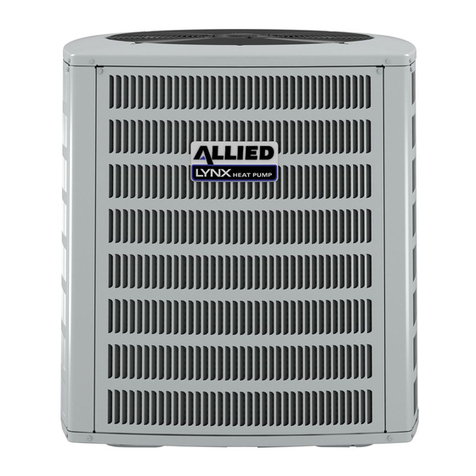
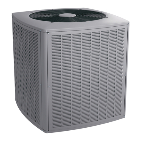
The outdoor section is to be installed on a solid foundation.
This foundation should extend a minimum of 2” (inches)
beyond the sides of the outdoor section. To reduce the
possibility of noise transmission, the foundation slab
should NOT be in contact with or be an integral part of the
building foundation. See Figure 2.
If conditions or local codes require the unit be attached to
pad or mounting frame, tie down bolts should be used and
secured to unit base pan.
Refrigerant Metering Device - Indoor Coil
For correct metering device, refer to chart below.
Outdoor Model Orice
Size
Indoor
Expansion
Device
Outdoor Model Orice
Size
Indoor
Expansion
Device
Outdoor Model Orice
Size
Indoor
Expansion
Device
4SCU13LE118P-1,4,5 0.053 A4TXV01 4SCU13LB118P-2 0.051 A4TXV01 4SCU13LC136T 0.073 A4TXV02
4SCU13LE118P-2,3 0.051 A4TXV01 4SCU13LB118P-3 0.053 A4TXV01 4SCU13LC148T 0.081 A4TXV02
4SCU13LE124P-1,2,3,4,5 0.057 A4TXV01 4SCU13LB124P-2,3 0.057 A4TXV01 4SCU13LC160T 0.090 A4TXV03
4SCU13LE130P-1,4,5 0.063 A4TXV01 4SCU13LB130P-2 0.065 A4TXV01 4SCU13LC136F 0.073 A4TXV02
4SCU13LE130P-2,3 0.065 A4TXV01 4SCU13LB130P-3 0.063 A4TXV01 4SCU13LC148F 0.081 A4TXV02
4SCU13LE136P-1 0.074 A4TXV01 4SCU13LB136P-2 0.069 A4TXV01 4SCU13LC160F 0.090 A4TXV03
4SCU13LE136P-2,3 0.073 A4TXV01 4SCU13LB136P-3 0.072 A4TXV01
4SCU13LE136P-4,5 0.072 A4TXV01 4SCU13LB142P-2 0.076 A4TXV02
4SCU13LE142P-1,2,3 0.076 A4TXV02 4SCU13LB148P-2 0.081 A4TXV02
4SCU13LE142P-4,5 0.074 A4TXV02 4SCU13LB148P-3 0.082 A4TXV02
4SCU13LE148P-1,2,3 0.081 A4TXV02 4SCU13LB160P-2 0.092 A4TXV03
4SCU13LE148P-4,5 0.082 A4TXV02 4SCU13LB160P-3 0.090 A4TXV02
4SCU13LE160P-1 0.092 A4TXV03
4SCU13LE160P-2,3,4,5 0.090 A4TXV02
Table 1.
These instructions are intended as a general guide and do
not supersede local codes in any way. Consult authorities
who have jurisdiction before installation.
Installation
NOTE: In some cases, noise in the living area has been
traced to gas pulsations from improper installation of
equipment.
• Locate unit away from windows, patios, decks, etc.
where unit operation sounds may disturb customer.
• Leave some slack between structure and unit to
absorb vibration.
• Place a sound-absorbing material, such as Isomode,
under the unit if it will be installed in a location or
position that will transmit sound or vibration to the
living area or adjacent buildings.
• In heavy snow areas, do not locate the unit where
drifting snow will occur. The unit base should be
elevated above the depth of average snows.
NOTE: Elevation of the unit may be accomplished
by constructing a frame using suitable materials. If a
support frame is constructed, it must not block drain
holes in unit base.
• When installed in areas where low ambient
temperatures exist, locate unit so winter prevailing
winds do not blow directly into outdoor coil.