Ecologix TP30 User manual

TP-M11
Installation Instructions
Thermal-pac & Thermal-duct
hot water air handler
ECOLOGIX HEATING TECHNOLOGIES INC.
221 Holiday Inn Dr.
Cambridge, Ontario
N3C 3T2
Phone: 519-658-4330
Fax: 519-658-9384
info@ecologix.ca
www.ecologix.ca

TP-M11
Table of Contents
IMPORTANT NOTES FOR THE INSTALLER..............................................................................................................3
TYPICAL PLUMBING CONNECTIONS.........................................................................................................................4
ELECTRICAL WIRING DIAGRAM.................................................................................................................................5
INTRODUCTION...................................................................................................................................................................9
HOW IT WORKS...................................................................................................................................................................9
COOLING....................................................................................................................................................................................9
HEATING ....................................................................................................................................................................................9
CONTINUOUS FAN......................................................................................................................................................................9
PRODUCT DESCRIPTION ..............................................................................................................................................10
CABINET ..................................................................................................................................................................................10
HEATING COILS ......................................................................................................................................................................10
FAN AND MOTOR....................................................................................................................................................................10
CIRCULATING PUMP ...............................................................................................................................................................10
CHECK VALVE ........................................................................................................................................................................10
CONNECTING TO AWATER HEATER...................................................................................................................................... 11
CONNECTING TO ABOILER..................................................................................................................................................... 11
EQUIPMENT SELECTION AND SIZING....................................................................................................................11
HEAT LOSS..............................................................................................................................................................................11
AIR HANDLER SELECTION......................................................................................................................................................11
DUCT LAYOUT ........................................................................................................................................................................12
INSTALLATION.................................................................................................................................................................13
AIR HANDLER MOUNTING .....................................................................................................................................................13
DUCTWORK .............................................................................................................................................................................13
RISK OF FREEZING..................................................................................................................................................................14
ELECTRICAL .....................................................................................................................................................................14
THERMOSTAT..........................................................................................................................................................................14
A/C CONDENSING UNIT .........................................................................................................................................................15
PUMP EXERCISER....................................................................................................................................................................15
START-UP PROCEDURES..............................................................................................................................................15
SERVICE AND MAINTENANCE ...................................................................................................................................16
TROUBLESHOOTING......................................................................................................................................................16
THERMOSTAT CALL ERROR ...................................................................................................................................................16
PUMP DOES NOT RUN ..............................................................................................................................................................17
PUMP IS NOISY AT START-UP..................................................................................................................................................17
WATER HEATER T&P IS WEEPING..........................................................................................................................................17
INSUFFICIENT OR NO HEAT .....................................................................................................................................................17
COLD WATER AT HOT FAUCET ................................................................................................................................................17
FAN RUNS FOR COOLING BUT NOT HEATING..........................................................................................................................17
HEATING DURING STANDBY MODE.......................................................................................................................................17
Thermal-pac AIR HANDLER PARTS & ACCESSORY LIST...................................................................................18
PRODUCT WARRANTY..................................................................................................................................................19

TP-M11
3
IMPORTANT NOTES FOR THE INSTALLER
)A Quick Check List
!Are the water connections to the water heater oriented in a way to avoid trapping air in
the heating circuit? (see diagram on next page)
!Is the purge valve installed on the return line from the air handler upstream from the
isolation valve?
!Is the air handler hung and isolated to avoid transmitting vibration through framing and
duct work?
!Are the isolation valves full-port? Restrictive valves will limit performance.
!Are Thermostat connections correct, including cooling and continuous run connections?
!Have the packing materials been removed from the blower and the pump ?
!Is there an installation manual for the home owner ?
!Is the unit accessible? Are there clearances for service and component replacement?
!Are the supply plenum and return duct/drop acoustically lined ? (at least 6ft. of the
return duct/drop and the supply plenum are recommended)
!Is the filter cover in place? Is a clean filter in place? Is the supplied filter rack
installed?

TP-M11
4
TYPICAL PLUMBING CONNECTIONS
If the water heater has
side connections, use
them for the air handler
TP-M11
5
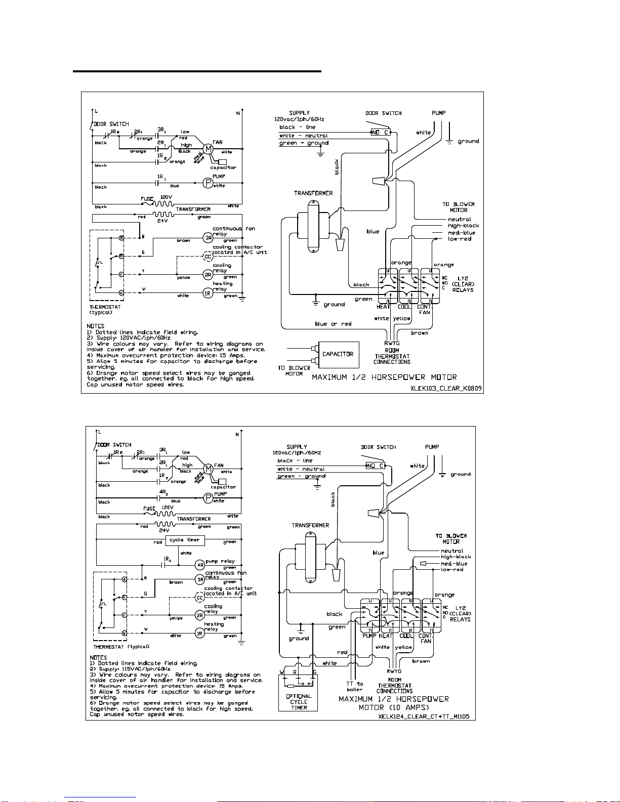
ELECTRICAL WIRING DIAGRAM
air handler electrical wiring schematic air handler electrical wiring layout -- XELK103
air handler electrical wiring schematic air handler electrical wiring layout -- XELK124 with Cycle Timer

TP-M11
6
For TP75, TDHV-48 and TDHV-60
air handler electrical wiring schematic air handler electrical wiring layout -- XELK113
air handler electrical wiring schematic air handler electrical wiring layout -- XELK134

TP-M11
7
Physical Properties
Cabinet dimensions Supply air
Return air water
inlet Shipping
Model Type abcd x e f x g and
outlet Weight
TP30, TDHV-12,
TDHV-18 20” 14” 24” 12”x16” 12”x16” 1/2” 80 lb.
TP45 to TP75,
TDHV-24 to
TDHV-60
22” 22” 31.5” 20”x20” 20”x20” 3/4” 110 lb.
Unit Specifications: thermal-pacTM air handlers
MODEL: TP30 TP60 TP65 TP75
*Heating Capacity (Btu/h) 120F water 21,000 43,000 47,000 55,000
*Heating Capacity (Btu/h) 130F water 28,000 56,000 61,000 71,000
*Heating Capacity (Btu/h) 140F water 30,000 60,000 66,000 77,000
*Heating Capacity (Btu/h) 160F water 37,000 77,000 85,000 100,000
*Heating Capacity (Btu/h) 180F water 48,000 95,000 104,000 122,000
(USGPM) Heating 2.3 4.5 4.5 4.5
Maximum Heating Airflow (CFM) 800 1200 1400 1900
Max. External Static Pressure (“wc) 0.3 0.4 0.5 0.3
Cooling Capacity –High (Tons) 2.0 3.0 3.5 5.0
Blower Motor Full Load (Amps) 55710
Circulator Full Load (Amps) 0.6 0.8 0.8 0.8
*based on 70F return air, high fan speed and 20F water temperature drop through the coil.
TP-M11
8
Unit Specifications: Thermal-DuctTM air handlers
MODEL TDHV-
12 TDHV-
18 TDHV-
24 TDHV-
30 TDHV-
36 TDHV-
42 TDHV-
48 TDHV-
60
Number of 3”
outlets1812 15 18 22 26 30 36
Cooling Capacity
(Tons) 1.0 1.5 2.0 2.5 3.0 3.5 4.0 5.0
*Heating Capacity
(MBH) 130F water 15 21 35 41 46 49 52 57
*Heating Capacity
(MBH) 140F water 18 25 41 48 54 57 61 67
*Heating Capacity
(MBH) 160F water 24 33 53 62 69 74 78 86
*Heating Capacity
(MBH) 180F water 30 40 65 76 85 91 96 105
(USGPM) Heating 2.3 2.3 4.5 4.5 4.5 4.5 4.5 4.5
Nominal Airflow
(CFM)2360 540 720 900 1080 1260 1440 1800
Max. Design ESP
Heat Only (“WC) 1.0 0.8 0.9 0.7 0.8 0.6 1.0 0.5
Max. Design ESP
Heat/Cool (”WC)30.9 0.7 0.8 0.4 0.5 0.3 -- --
Blower Motor Full
Load (Amps) 44557710 10
Circulator Full
Load (Amps) 0.6 0.6 0.8 0.8 0.8 0.8 0.8 0.8
1. Minimum Required. Refer to Design and Installation Instructions for options.
2. All air flows at high speed.
3. Using Ecologix cased slab cooling coils. Above 3.5 tons, use an A-coil.

TP-M11
9
INTRODUCTION
Thermal-pac™ and thermal-duct™ air
handlers are designed for use with
hydronic (boiler) systems or in
combination space and water heating
systems (Combo Systems). Combo
heating systems use the home’s water
heater to provide both the space heating
and domestic hot water, eliminating the
need for a furnace.
Combo heating systems are ideally
suited for single-family homes,
townhouses and apartments where the
cost of a furnace does not make sense or
space requirements are limited. They
are also great for additions, renovation
and finished basements as a
replacement for, or in addition to the
existing heating system. Ecologix air
handlers are also great for hydronic
heating systems using ground-source
heat pumps. They are the smallest units
available in their capacity range.
Thermal-pac™ and thermal-duct™ air
handlers are designed to take the
guesswork out of system sizing and
installation. Matched specifically to
common water heater sizes, Ecologix air
handlers can be quickly sized using the
quick sizing information in our spec
sheets or from air handler performance
curves. For applications requiring
special consideration, call 519-658-
4330 for answers to questions related to
sizing, installation or trouble-shooting for
any of Ecologix air handlers or water
heaters.
Ecologix provides you with the quietest
operating air handler available. By using
large capacity, high output heating coils,
the air handlers deliver more heating per
volume of air, which means warmer
delivered air temperatures.
Thermal-pac™ air handlers are intended
for conventional duct systems and
Thermal-duct™ air handlers are
intended for small-D™ duct systems with
higher operating static pressure. Refer
to the small-D™ design manual for more
details on duct design and installation.
HOW IT WORKS
Cooling
In a typical installation, a call for cooling
will bring on the fan at the selected air
speed and the outdoor cooling unit.
The installer can select one of three
speeds that the air handler will operate at
during cooling mode.
Heating
A call for heating will bring on the pump
and the fan at the selected heating
speed. Heating capacity may be
adjusted by selecting one of three fan
speeds. Heating has priority over
cooling or continuous fan. The factory
default is low.
Continuous Fan
When the thermostat fan switch is set to
continuous fan, the fan will run at the
selected speed. The factory default is
low. When there is a call for heating or

TP-M11
10
cooling, the normal heating or cooling
speed will over-ride the continuous fan setting. Once the thermostat is satisfied,
continuous fan speed will resume.
PRODUCT DESCRIPTION
Ecologix air handlers are certified by:
Entela Inc.
81 Kelfield St., Unit 7
Toronto, Ontario
M9W 5A3
Ph: 416-241-8427
Fx: 416-241-0682
Ecologix air handlers are in conformity
with the following standards:
CAN CSA-22.2 No. 236M95
UL 1995 2nd Ed.
As shownin certification report number:
0301154695, File number 8502, dated:
01/27/03
Cabinet
All cabinets have a tough, durable low
maintenance pre-painted finish.
Cabinet dimensions are designed to
provide maximum installation flexibility.
Refer to installation requirements for
more details.
Heating Coils
All heating coils are potable water grade
copper suitable for use in plumbing
systems. No lead solder is used in any
component construction. All coils and
internal piping conform to ASTM B68 or
ASTM B88 standards.
High-density aluminum fins provide
maximum heat transfer for small coil
surface.
Fan and Motor
All fans are wide body dynamically
balanced for extra quiet operation.
Multi-directional sleeve bearing motors
allow mounting in any direction for
maximum installation flexibility.
Circulating Pump
The circulating pump is matched for
maximum performance. Air handlers
come with internally mounted pumps for
ease of installation. Air handlers can be
special ordered with external, field
installed pumps, when it is desirable to
locate the circulator below the air
handler, such as in attic installations.
Check Valve
Check valves serve two purposes:
•protect against back-flow of water to
avoid short circuiting around the
water heater during domestic water
use.
•protect against thermal siphoning.
Thermal siphoning is flow of water
through the space heating circuit while
the circulating pump is not operating due
to hot water rising by natural convection.
During summer months this will cause
overheating, interfere with air
conditioning and waste energy.

TP-M11
11
All Ecologix air systems come supplied
with spring loaded, vertical lift check
valves. These check-valves have been
tested and proven to resist thermal
siphoning for installations where the air
handler elevation does not exceed the
distance above the water heater shown
in the table below.
Check Valves
valve size Maximum
elevation
1/2”(12mm) 25 feet(8 metres)
3/4”(20mm) 50 feet(15 metres)
Connecting to a Water Heater
Any properly sized gas, propane or oil
fired water heater will work in a combo
heating system. Make sure the water
heater being used is approved for combo
applications. (Most manufacturers’
heaters are approved.) Tank-less water
heaters may reduce the capacity of air
handlers due to the higher internal
pressure drop. (Call Ecologix for details)
Connecting to a Boiler
All Ecologix air systems are compatible
for use with boilers. Standard drawings
are available from Ecologix for most
boiler applications.
EQUIPMENT SELECTION AND SIZING
Proper sizing of system components is
crucial for proper operation.
Steps for sizing and selection:
1) Obtain room by room heat loss and/or
heat gain
2) Determine heating water temperature
3) Select air handler from specification
sheet
5) Determine duct layout
Heat Loss
Make sure a proper room-by-room heat
loss and heat gain for the dwelling is
calculated using HRAI, ASHRAE or other
approved sizing method.
Air Handler Selection
Select the desired air system that will
meet 100%-140% of the heating load
and 80%-120% of the cooling load.
If using a boiler system, select a boiler
that has an output that meets or exceeds
the heat loss of the space being heated.
If the boiler is meeting additional loads,
size the boiler to meet the total combined
load.
For combo heating systems, use an
approved sizing method such as the
Unified Combo Guidelines published by
HRAI. In areas where the UCG or a local
sizing code is not applicable, use the
following method for sizing combo
systems:
1) Select an air handler that meets or
exceeds the calculated heat loss at the
water heater operating temperature
(130F/55C or 140F/60C).

TP-M11
12
2) Select a water heater with an output
that is at least 120% of the heat loss
Duct Layout
Make sure a proper duct design has
been completed for the dwelling using
HRAI, ASHRAE or other approved
design method.
Supply air Plenum
Provide asupply air plenum that is the
same dimensions as the outlet flanges of
the air handler and at least 36 inches
long. Acoustical lining is recommended.
A smooth, square-to-round transition
may be used in place of the supply air
plenum for horizontal installations where
there is only one supply main.
For vertical applications where the air
conditioning coil is installed in the supply
air plenum, the cooling coil must be
supported at least 4 inches above the
heating coil face on brackets or channel
to ensure unimpeded airflow through the
heating coil.
Plenum takeoffs may be mounted on the
end of the plenum or the sides of the
plenum, but not both. Spin in collars or
transition takeoffs may be used, but not
both.
Supply mains
Plan duct layout to avoid branch runs in
outside walls or attics and to minimize
the length of the main duct
Where practical, provide parallel main
ducts to various floors or zones rather
than running a single larger duct with
tees. For applications with 3 or more
floors or any application where a large
seasonal adjustment in airflow is
anticipated, parallel main supply ducts
must be used. Volume dampers in each
of the main supply ducts must be
installed and must be accessible for
seasonal adjustments. For example; a 4-
storey town house will probably require
vastly different airflow rates for the upper
floors between cooling and heating
seasons. If there are two main supply
trunks, the supply trunk serving the upper
2 floors can be damped down in the
heating season to better balance the air
flows.
Supply mains may be round duct or
equivalent rectangular duct.
Round duct can be spiral duct, welded or
snap lock seams.
Rectangular duct must be at least 26
gauge for all dimensions. The aspect
ratio for square ducts (wide dimension
over short dimension) shall not exceed
2.5 to1.
Return air duct
The return air duct should be sized for a
total pressure drop of not more than
0.15”w.c. Using conventional sizing
methods and installed in accordance with
HRAI guidelines or equal. It is
recommended that the return air duct or
drop be acoustically insulated for at least
6 feet nearest the air handler.
Refer to the small-D™ design guide for
additional requirements for small
diameter/higher static duct applications.

TP-M11
13
INSTALLATION
The installer must adhere strictly to all
local and national code requirements
pertaining to the installation of this
equipment.
Detailed instructions are shipped with all
accessory items and should be followed
in detail.
Air Handler Mounting
The Ecologix air handler can be
installed in any direction. Its compact
dimensions even allows for installation
between joists. The air handler can be
floor mounted or hung from straps. Some
precautions must be observed for some
of the possible mounting positions.
For installations where the access door
faces up or down, select an air handler
with an external pump to avoid the pump
being mounted with its shaft vertical. The
pump shaft must be mounted horizontally
to avoid premature failure.
The air handler can be hung by securing
straps through any of the existing screw
holes in the cabinet. When the existing
screw is too short for securing a
mounting strap, a longer screw can be
used provided care is taken not to
damage any internal components.
When fastening straps using screws
other than those supplied with the
cabinet, special care should be taken in
the vicinity of the coil to avoid tube
puncture.
Note: Do not put screws into the
cabinet directly in front of and behind
the coil.
3/4” screws can be safely installed on
either side of the coil.
The cabinet is designed so that the
return air can be located on either side of
the cabinet, through the bottom of the
cabinet, or from the back. Position the
filter rack so that the filter is readily
accessible.
Install the air handler with the door firmly
screwed in place to make sure the
cabinet remains square.
Provide at least 2 feet (0.75 metres) of
service clearance in front of the access
panel of the air handler. Zero clearance
is acceptable on all other faces.
Ductwork
General
Ductwork installed in unheated spaces
such as attics must be installed between
the insulation and the heated space.
Provide at least R-12 of insulation above
ducts. If cooling is required, the branch
and trunk lines must be insulated and
sealed with a vapour barrier prior to
applying house insulation.
If a fresh air duct is required, make
connection to return air plenum at least 6
feet upstream from filter. Insulate all
fresh air ducts.
Supply Ductwork
Supply trunks may be square or round.
SEAL all joints and seams with metal
tape or sealing compound. Volume
dampers for each of the main supply
trunks must be accessible for balancing.
(Near the supply plenum is preferred)

TP-M11
14
Locate outlets at least 6 inches from
outside walls or window coverings.
Return Ductwork
Return air plenum should be the same
cross sectional area as the air handler
return air opening. In vertical
installations, a conventional return air
drop and elbow is acceptable. IT is
recommended that the return duct /drop
be acoustically lined for 6 feet nearest
the air handler.
Risk of Freezing
Steps must be taken to prevent the hot
water coil from freezing. Coils that have
failed due to freezing and damage
caused by frozen coils are not covered
under warranty.
HRV and Fresh air connections
Fresh air and HRV connections to
ductwork can pose a risk of dumping cold
air into ductwork during periods of stand-
by or continuous run. Calculate mixed
air stream temperatures and provide
interlock controls to prevent freezing
conditions.
Evaporator coils
Evaporator cooling coils that are
mounted above the hot water coil pose a
risk to the hot water coil in the event that
the compressor contactor on the
condenser sticks in the on position.
When the call for cooling is satisfied, the
blower will stop running and allow cold
air from the evaporator coil to fall on to
the hot water coil.
Attic and crawl spaces
Air handlers may be located in areas
subject to freezing conditions. It is
necessary to protect the hot water coil
from freezing.
ELECTRICAL
Warning! -Make sure unit is properly
grounded. Locate air handler on a
separate electric circuit, or use the same
circuit as the water heater or boiler.
Air handler wiring diagrams are located
on the blower for easy reference during
installation and servicing.
Nameplate data is located on the side of
the unit.
All air handlers operate on
115VAC/1ph/60hz line voltage. All
control circuits are 24 VAC. One leg of
the 24 VAC is grounded to the chassis.
Thermostat
The thermal-pac™ and thermal-duct™
air handlers are compatible with most
standard heat/cool, heat pump, “electric
heat”, “gas heat”, set-back or electronic
thermostat. Some electronic
thermostats (primarily “power robbing”
types) require the addition of a resistor
between the W & C terminals
and the Y & C terminals. This is usually
covered in the thermostat instruction
manual. A 1,000 ohm, 5 watt resistor on
each of the W and Y terminals will
usually be enough to drain the current
required to power the thermostat. Some

TP-M11
15
thermostats will need 250 ohm, 10 watt
resistors on each of the W and Y
terminals.
Heat Anticipator Setting
For optimum comfort the anticipator
setting should be set to provide
approximately 4 cycles per hour
Typical Heat
Anticipator Setting
0.25 amps
Thermostat wire from the thermostat is
connected to the wires located inside the
air handler. The thermostat should be
connected as follows:
R –power (red) (24vac)
W –heating (white)
Y–cooling (if present) (yellow)
G –continuous run fan (if present on
thermostat) (black or brown)
Boiler
If the optional fourth relay is installed, the
yellow wires labeled TT on the relay are
dry contacts for connectionto a boiler or
external pump. A relay for the boiler may
be field installed. The relay shall be
24VAC, SPST-NO and the coil
connected to W and ground.
A/C Condensing Unit
Connect to Y (yellow) and C (green).
Pump Exerciser
An optional pump exerciser with fourth
relay may be ordered factory installed or
may be field installed. Connect to R
(red), W (white) and C (green). It will
operate the pump once a day for 30
seconds. NOTE: It’s first on-cycle will be
as soon as power is applied to the air
handler.
START-UP PROCEDURES
Do not start the air handler or water
heater until ALL air has been purged!
1.Fill the boiler loop or water heater with
water, but do not start it.
2.Purge all air from the boiler heating or
domestic water system.
3.Purge all air from the space-heating
loop by closing the isolation valve on the
return leg of the loop and open the drain
to purge air. Open the return leg isolation
valve and then close the drain valve.
4.Start the boiler or water heater
according to the manufacturer’s
instructions. Set the design water
temperature and wait for the system to
shut off. You can check that the water
heater is set properly by running hot
water from a faucet into a glass. Using a
thermometer measure the temperature of
the water as soon as the water heater
burner shuts off. If the set-point
temperature is too low or is above 140F,
reset the tank control, run water until the
burner starts again and repeat the
measurement.
5.Turn on the power to the air handler
and set the room thermostat for heat to
energize the fan and pump. If a gurgling
sound is present, it should subside within

TP-M11
16
one minute. If noise is still present after
one minute, repeat step 3 to purge air as
necessary.
6.Check pipes for heating to make sure
there is flow.
SERVICE AND MAINTENANCE
Filter
The Ecologix air handler is provided with
a disposable pleated filter. This filter
should be inspected monthly and
replaced as required. Replacement
filters are available from Ecologix.
Duct cleaning
If proper filter maintenance is adhered to,
duct cleaning will not be required for the
life of the equipment.
Coils
Air conditioning and heating coils should
not require cleaning if the filter
maintenance schedule is adhered to. If a
filter is damaged or collapses from
plugging, dust may foul the coils. If this
happens, replace the filter and carefully
vacuum the heating coil. The fan may
need to be removed to gain access to the
face of the heating coil.
Air conditioning coil
At the start of each cooling season,
check the drain connection to the cooling
coil to ensure it is free of debris. If a
plugged air conditioning coil is
suspected, call a service technician for
testing and cleaning.
Fan and motor
Check fan for dust once a year. If dirty,
vacuum or wash to remove dust.
Keeping the fan blades clean will reduce
noise and improve the capacity and
efficiency of the heating system
Pump
The circulating pump is water lubricated
and should require no regular
maintenance. The system control has a
cycle timer to exercise the pump even
during prolonged periods of no heat to
avoid seizing from long idle periods.
TROUBLESHOOTING
Thermostat Call Error
First, review “How It Works” on page 6
for normal operation.
If there is a call for cooling and call for
heating at the same time, the heating call
will have priority and the air conditioning
condenser (outdoor unit) will come on.
Check the thermostat for correct wiring.
Some electronic thermostats and power
robbing thermostats apply a voltage to
the W and/or Y and/or G terminal. With
the thermostat off, the voltage at W, Y
and G should be zero compared to
ground (C). Excessive voltage will be
interpreted as a call from the thermostat.

TP-M11
17
Pump does not run
In areas where hard water is present the
pump may “stick” and fail to run. Often,
closing the isolation valve on the return
leg and opening the drain port so that
water flows through the pump can free
this. For Grundfos pumps, remove the
screw-on cover from the face of the
pump, and rotate the shaft one turn with
a slotted screwdriver. If either method
fails to free the pump, removal for
cleaning or replacement is necessary.
The daily pump exerciser will help
prevent pump sticking.
Pump is noisy at start-up
Air is present in heating loop. If sound
has not diminished within 1 minute,
purge air in accordance with the Start-Up
procedures. If heat source is a water
heater, check to make sure branch
connections for heating loop are
horizontal to prevent the collecting of air
in the heating loop. See the drawing:
Typical Plumbing Connections at the
front of this manual.
Water heater T&P is weeping
A check valve or back-flow preventer
may have been installed in the system.
Some form of pressure relief may be
required. Options are:
•Install expansion tank
•Install pressure relief valve; locate
outlet over laundry tub or floor
drain.
•Install combination toilet
tank/pressure relief valve
Insufficient or no heat
•Plugged air filter or coil. Refer to
Maintenance section for filter care
and coil cleaning.
•Air in heating loop; purge system.
•Inlet and outlet connections to air
handler backwards; reverse
connections.
•Water heater supply tube (dip
tube) is restricted or damaged;
check and/or replace.
•Supply water temperature set too
low or not calibrated properly;
check water temperature. In the
case of water heater; If the
temperature has been set low
because of homeowner
preference, it may be necessary to
install an anti-scald valve to
control the faucet temperature and
raise the operating temperature of
the water heater.
•Restrictions in heating loop;
remove restrictions, check valve
stuck, isolation valves too
restrictive, left partially closed after
purging or closed valve.
•Water heater supply temperature
is unstable. Check water heater
setting and temperature sensors
for good contact on coil headers.
Cold water at hot faucet
When heat source is a water heater, the
most probable cause is reverse flow
through the heating loop from a stuck
check valve; repair or replace valve.
Fan runs for cooling but not heating
Room thermostat may be connected
improperly. Refer to Electrical section or
wiring schematic on door of air handler
for proper installation.
Heating during Standby Mode
Probable cause is thermal siphoning.
See check valve description for details;
repair or replace check valve. Check
elevation of air handler above water
heater to see if motorized valve required
for positive shut-off.

TP-M11
18
Thermal-pac AIR HANDLER PARTS & ACCESSORY LIST
Part No. Description
TP30
TDHV-18
TP60
TDHV
-24
TDHV
-30
TP65
TDHV
-36
TDHV
-42
TP75
TDHV
-48
TDHV
-60
UC12163 Hot Water Coil -- 12”x16” S
UC18203 Hot Water Coil –20”x18” SSS
GUPS15-58RUC Pump-Grundfos c/w check SSSS
GUP15-42BUC5 Pump-Grundfos 1/2” c/w check A
GUP15-42BUC7 Pump-Grundfos 3/4” c/w check AAA
T006B Pump –Taco 006 1/2” sweat A
T008B Pump –Taco 008 3/4” sweat AAA
xPLC004 Vertical lift check valve 1/2”A
xPLC006 Vertical lift check valve 3/4” AAA
xELR024DPST Pump/Blower Relay 24VAC AAAA*
xELR024DPDT Pump/Blower Relay 24VAC SSSS*
xELR024DPDT2Blower Relay 24VAC (30 Amp)AAAS*
XELR01TIMER Cycle Timer/Pump Exerciser OOOO
xELT002 Transformer 24VAC, 40 VA SSSS
xELT003 Transformer 24VAC, 25 VA AAAA
xELD002 Door interlock switch SSSS
XELM002 EC Blower motor -- -1/4 HP S
XELM003 EC Blower motor -- -1/3 HP AS
XELM004 EC Blower motor -- -1/2 HP AS
XELM006 EC Blower motor -- -3/4 HP S
xBLF105T Blower –10x5T DD S
xBLF108 Blower –10x8 DD SS
xBLF128T Blower –12x8T DD S
PF1418 Pleated filter -14” x 18” S
PF2222 Pleated filter –22” x 22” SSS
PME01 External pump module,
½” plumbing c/w check valve O
PME02 External pump module,
¾” plumbing c/w check valve OOO
CPVA Valve Assembly –¾” full port sweat
ball valves plus hose bib for return OOOO
S=Standard, A=Alternate, O=Option or Accessory
* High current (15Amp. min.) relays required for 3/4hp blower motor.

TP-M11
19
PRODUCT WARRANTY
221 Holiday Inn Drive, Phone: 519-658-4330 www.ecologix.ca
This product is warranted by Ecologix Heating Technologies Inc to be free from defects in materials and
workmanship that affect product performance under normal use and maintenance within the applicable
periods specified below. Replacements furnished will carry only the un-expired portion of the original
warranty.
Two-Year Parts
Ecologix Heating Technologies Inc will provide replacement parts for ANY part that fail within two years
of purchase, subject to the terms below.
Five-Year Parts
Ecologix Heating Technologies Inc will provide replacement parts for any heating coils, cooling coils,
cabinetry and piping that fail within five years of purchase, subject to the terms below.
Terms
vReasonable proof of original purchase date must be provided in order to establish the effective date
of the warranty, failing which, the effective date will be based on the date of manufacture plus thirty
days.
The warranty does not cover failure or damages caused by:
Øimproper installation or operation
Øaccident, abuse or alteration
Øoperation of device at temperatures or pressures outside of the rated capacities
Ølime or scale deposits
Øcorrosive operating environment
Øequipment moved from original installation location
vReplacements furnished under this warranty will be F.O.B. Ecologix Heating Technologies Inc
product distribution points in the United States and Canada. They will be invoiced at regular prices.
The account will be credited the full amount when the defective part is received by Ecologix,
examined and approved as a valid warranty.
vWarranty applies to the original purchaser, but may be transferred to another owner provided the
equipment is not moved from the original installation site.
vThis warranty does not apply to labour, freight or any other cost associated with the service repair
or operation of the product.
vEcologix shall not be liable for any direct, special, incidental or consequential damages caused by
the use, misuse, or inability to use this product.
vEcologix is under no legal obligations to rectify, including but not limited to, lost profits, downtime,
good will, damages to, or replacement of equipment and property
vPurchaser assumes all risk and liability of loss, damage or injury to purchaser and purchaser’s
property and to others and their property arising out of the use, misuse or inability to use this
product.
This manual suits for next models
3
Table of contents
Popular Water Heater manuals by other brands
Beacon/Morris
Beacon/Morris twin-floIII installation instructions

A.O. Smith
A.O. Smith DSE-5 THRU DSE-120 Installation and operaion manual

Ariston
Ariston BOOSTER user guide

Maytag
Maytag HVN41240PCGA user guide

Rheem
Rheem MPi 551 Series Owner's guide and installation instructions

HTP
HTP HPW-50-6 Installation start-up maintenance parts

Aparici
Aparici SB15 User and installation manual

Solahart
Solahart 150RD18 owner's manual

Nofer
Nofer SB150N User and installation manual

STIEBEL ELTRON
STIEBEL ELTRON DEL 18 SL electronic LCD Operation and installation

Sanyo
Sanyo SHP-TH90GDN-SW Technical manual

TiSUN
TiSUN Pro-Clean installation instructions


