6
29785 R3 3/10/2004
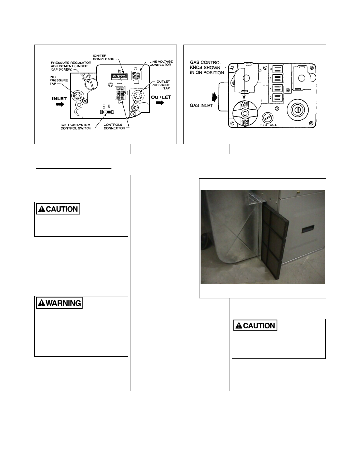
IF CLEANING RATHER THAN REPLACING THE
FILTER, UNLESS THE FILTER IS THOROUGHLY
WASHED AND DRIED, BE SURE THAT THE
FILTER IS RE-INSTALLED WITH THE AIRFLOW
DIRECTION IDENTICAL TO ITS PREVIOUS USE.
REVERSING THE FILTER WILL CAUSE DUST
TRAPPED WITHIN THE FILTER TO BREAK
FREE AND RECIRCULATE WITHIN THE DUCT
SYSTEM.
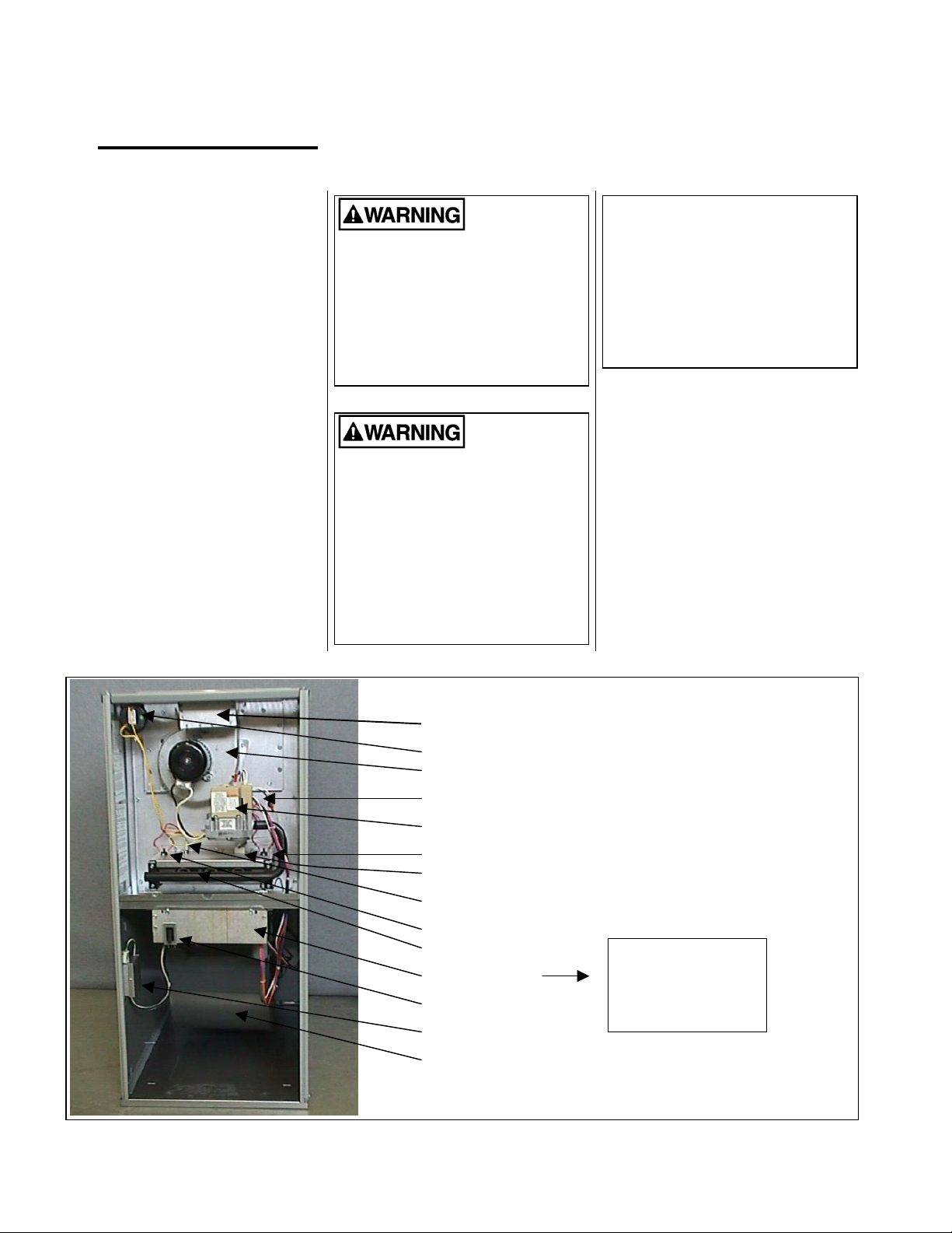
LUBRICATION
Minimal lubrication is required for your
furnace. The induced blower assembly
motors have sealed bearings. The
bearings contain permanent special
purpose lubricants. Attempting to force
common oil into the induced blower
motor bearings will deteriorate the
original lubricant and shorten bearing
life.
DISCONNECT ELECTRICAL POWER
TO THE FURNACE BEFORE
ATTEMPTING TO LUBRICATE THE
BLOWER MOTOR. FAILURE TO DO
SO COULD RESULT IN SEVERE
PERSONAL INJURY OR DEATH.
The circulating fan may have perma-
nently lubricated ball bearings or
sleeve bearings. If the blower motor is
equipped with sleeve bearings, peri-
odic oiling is required. If the fan motor
runs continuously, the bearings should
be oiled yearly. If the fan runs occa-
sionally, (automatically), the bearings
may be oiled after the second year. 4 -
6 drops of SAE 20 non-detergent oil is
ideal. The oiling ports are normally (but
not necessarily) located on the outside
edge of the motor end bells. The inner
oil port is difficult to reach without a
“tele-spout” or similar type oiler. If you
cannot see an oil port, we recommend
that you leave this part of the mainte-
nance to your service contractor.
DO NOT USE AUTOMOTIVE MOTOR OIL,
HOUSEHOLD OIL, GENERAL-PURPOSE OIL,
ETC. THESE OILS WILL SHORTEN THE LIFE
OF THE MOTOR.
DO NOT OVER-OIL THE ELECTRIC MOTOR.
EXCESS OIL WILL SHORTEN THE LIFE OF THE
MOTOR.
ROUTINE EXAMINATION
It is good practice to give a quick in-
spection of your furnace each time you
inspect or clean the air filter. Things to
check:
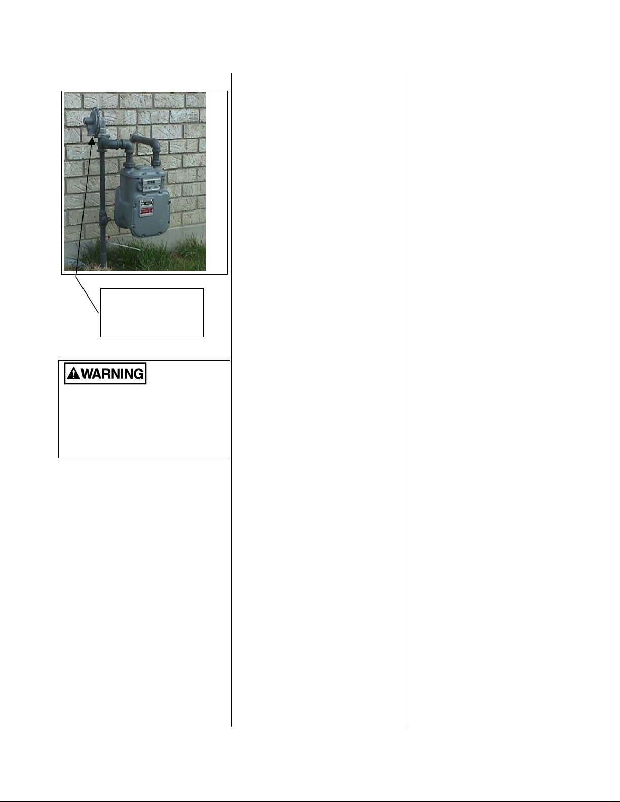
· All areas around the vent connec-
tor and chimney should be clear
and free of obstructions.
· Check the venting to ensure that it
is still fastened to the furnace. It
should not sag, and should have a
¼ inch to the foot slope upwards
to the chimney. It should be physi-
cally sound, without holes or ex-
cessive corrosion.
· The return air duct connection
must be sound and securely fas-
tened to the furnace casing. In
most cases, the filter rack provides
the means to connect the return
air to the furnace. There should be
no return air inlets in the vicinity of
the furnace.
· All ductwork should be secured to
the furnace, and all ductwork
should be solidly supported
throughout the heating system.
· The furnace should be well sup-
ported on a level floor, or, by the
means used to suspend the fur-
nace in a horizontal configuration.
Base support should be physically
sound without sagging, cracks,
gaps, etc. around the base so as
to provide a seal between the
support and the base.
· Check the furnace for obvious
signs of deterioration.
· The gas burner should be ob-
served from time to time during the
heating season to ensure that the
flames are clean and blue. A bit of
orange color in the flame is not
likely to be a problem and is
probably dust particles burning. If
you observe lazy yellow flames,
call your heating or service con-
tractor immediately. The yellow
flames inevitably lead to soot-ups.
FURNACE APPEARANCE
The furnace exterior finish is a durable
automotive like coating. It may be
washed with mild soap if necessary.
Galvanized metal surfaces require no
maintenance.
CLEANING
It is advisable to keep dust build-up on
warm surfaces to a minimum, since
dust, in some cases, can be a combus-
tible.
Dust build-up in the circulating fan can
impair blower performance; therefore,
reduce efficiency. Because the blower
wheel is fastened directly to the blower
motor, we recommend that major
cleaning be left to your service contrac-
tor.
DO NOT PERMIT WATER OR CLEANING SOLU-
TIONS TO ENTER THE ELECTRIC MOTOR.
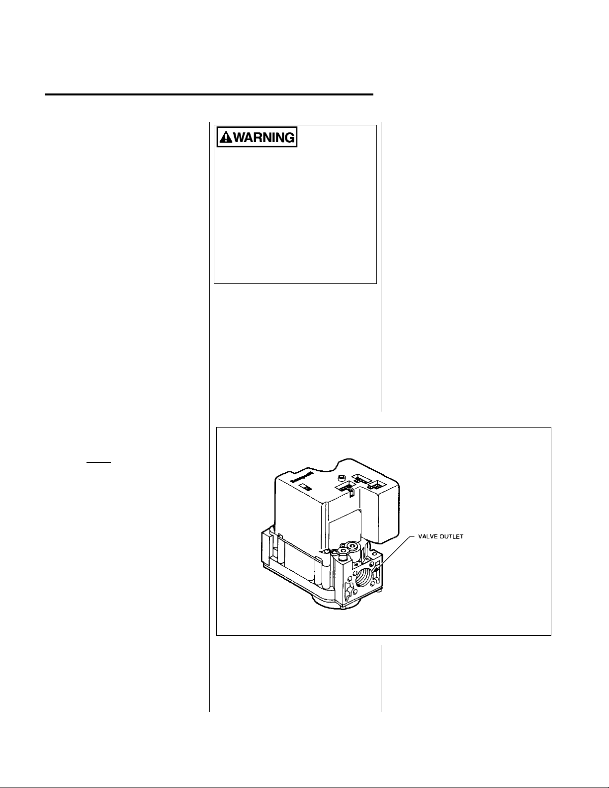
The burner area should be inspected
and cleaned periodically. Be careful
when cleaning around the burner area.
The hot surface igniter is fragile and
will break easily. Do not touch the hot
surface igniter or flame rod
NEVER ATTEMPT TO CLEAN THE
BURNER AREA WHILE THE
BURNERS ARE OPERATING. DOING
SO MAY RESULT IN EXPLOSION OR
FIRE RESULTING IN SEVERE
PERSONAL INJURY OR DEATH.
ALWAYS DISCONNECT THE
ELECTRICAL SUPPLY TO THE
FURNACE BEFORE REMOVING THE
BURNER COMPARTMENT ACCESS
DOOR.