ECU ECU-57N User manual

ECU-57N
/ ECU-88L
/ ECU-88N
INSTRUCTION MANUAL
LOW
OIL
PRESSURE
HIGHWATER
TEMPERATURE
OVERCRANK
OVERSPEED
ENGINE STARTED
FRONT
VIEW
SIDE
VIEW
BACK VIEW SIDE VIEW
These
units
are
the
most
advanced,
rugged
and
compact
engine
control
modules
we
have
ever
built. They are simple to use
but
this
manual
will
assist
both
engineer
and
mechanic
alike in the installation
and
operation
of
these controls.
The
following
pages
have
in order:
wiring
and
operation, expansion, adjustment,
specifications,
physical
drawing, drilling guide
and
warranty
information.
•
SPECIFICATIONS
Temperature Range
Voltage Range
Vibration
Standby Current
Operating Current
Maximum life cycles
Starter and
Fuel
Cutout
Signal outputs (total)
Speed input voltage range
Input Impedance
Weight
Crank Cycle Time Single
Crank Cycle Time Multi
Crank attempts
Low
oil
pressure delay
Crank disconnect trip
Overspeed trip
Verify mode
-40
TO
+85
C
9 to
28
VDC
10
G's
0 Amps
200
mA
50
000
5
Amps
1
Amp
2
to
15
Volts
5 kohms
12
oz.
2 sec
to
15
min
2
to
60
sec
1
to
8
1
to
60
sec
250
Hz
to
8500
Hz
250
Hz
to
8500
Hz
87
%
of
set
point
PHYSICAL DRAWING
INCH
MM
BACK VIEW
.260
1.50
6.6
38.1
SIDE VIEW
Mounting holes will accept No. 8 or No. 6 screws.
All specifications are subject
to
change
without
notice.
This
information
front
and back is protected
by
copyright
1996
and
ECU® is
a registered trademark
of
Engineering Concepts Unlimited Inc.
8950
Technology Drive Fishers, IN.
46038
Phone
317-849-8470
Need Replacement Parts?
Shop Online by Clicking Here
REMOTE
STANDBY
FUEL
RELAY
START RELAY
HIGH WATER TEMP
LOW OIL
PRESS
MAGNETIC
PICKUP
REMOTE
START
CONTACTS
6
5
4
3
1
15
14
13
X1
FOR
INFORMATION
ON
SETUP
OF
POTS
AND
SWITCHES
SEE
ADJUSTMENTS
PAGE
AUTO
OFF
MANUAL
LOW OIL
PRESSURE
LAMP
HIGH WATER TEMP LAMP
OVERCRANK
LAMP
OVERSPEED
LAMP
ENGINE STARTED LAMP
COMMON
ALARM
LAMP
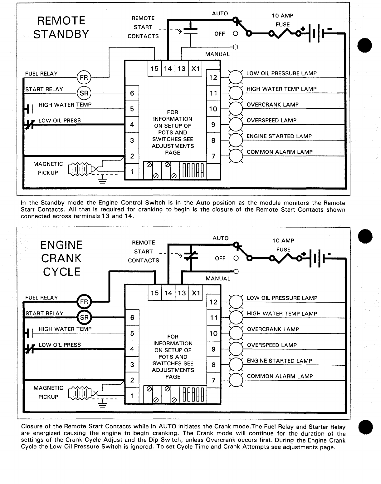
In
the
Standby
mode
the
Engine
Control
Switch
is in the
Auto
position
as
the
module
monitors
the Remote
Start
Contacts.
All
that
is required
for
cranking
to
begin is
the
closure
of
the Remote
Start
Contacts
shown
connected across terminals
13
and
14.
ENGINE
CRANK
CYCLE
FUEL
RELAY
START RELAY
HIGH WATER TEMP
LOW OIL
PRESS
MAGNETIC
PICKUP
REMOTE
START
CONTACTS
15
14
13
X1
6
5
FOR
INFORMATION
4
ON
SETUP
OF
POTS
AND
3 SWITCHES
SEE
ADJUSTMENTS
2 PAGE
1
AUTO
OFF
MANUAL
LOW OIL PRESSURE LAMP
HIGH WATER TEMP LAMP
OVERCRANK
LAMP
OVERSPEED LAMP
ENGINE STARTED LAMP
COMMON
ALARM
LAMP
Closure
of
the
Remote
Start
Contacts
while
in
AUTO
initiates
the
Crank
mode.The
Fuel Relay and Starter Relay
are energized causing
the
engine
to
begin cranking. The Crank mode will
continue
for
the duration
of
the
settings
of
the
Crank Cycle
Adjust
and
the
Dip
Switch,
unless Overcrank occurs
first.
During
the
Engine Crank
Cycle
the
Low
Oil Pressure
Switch
is ignored. To set Cycle Time and Crank
Attempts
see
adjustments
page.
•
•
•
•
•
•
ENGINE
REST
CYCLE
FUEL RELAY
START
RELAY
HIGH WATER TEMP
LOW OIL
PRESS
MAGNETIC
PICKUP
REMOTE
START
CONTACTS
6
5
4
3
1
15
14
13
X1
FOR
INFORMATION
ON SETUP
OF
POTS
AND
SWITCHES
SEE
ADJUSTMENTS
PAGE
AUTO
OFF
MANUAL
LOW OIL PRESSURE LAMP
HIGH WATER TEMP LAMP
OVERCRANK LAMP
OVERSPEED
LAMP
ENGINE STARTED LAMP
COMMON
ALARM
LAMP
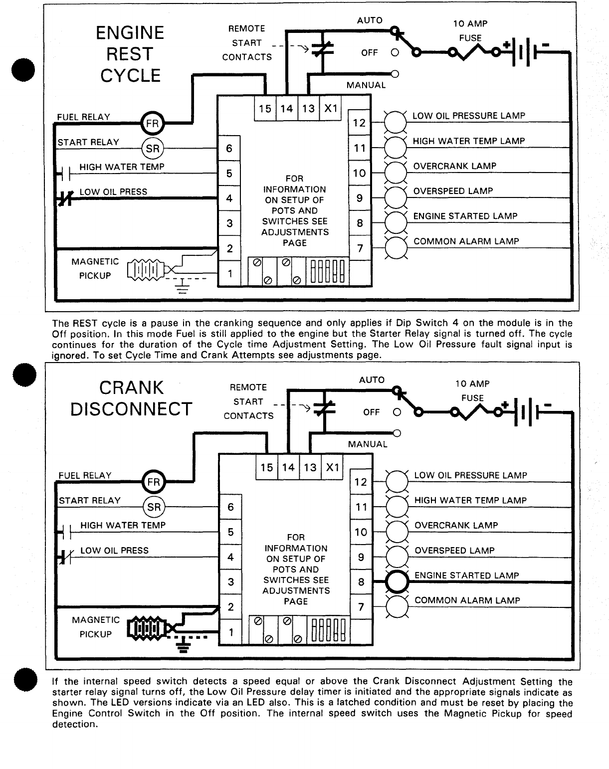
The REST cycle is a pause in
the
cranking sequence and
only
applies
if
Dip
Switch
4 on
the
module
is
in the
Off
position. In
this
mode
Fuel is still applied
to
the
engine
but
the
Starter Relay signal
is
turned
off.
The cycle
continues
for
the
duration
of
the
Cycle
time
Adjustment
Setting. The
Low
Oil Pressure
fault
signal
input
is
ignored. To set Cycle
Time
and Crank
Attempts
see
adjustments
page.
CRANK
DISCONNECT
FUEL RELAY
START
RELAY
HIGH WATER TEMP
LOW OIL
PRESS
MAGNETIC
PICKUP
REMOTE
START
CONTACTS
6
5
4
3
1
15
14
13
X1
FOR
INFORMATION
ON SETUP
OF
POTS
AND
SWITCHES
SEE
ADJUSTMENTS
PAGE
AUTO
OFF
MANUAL
LOW OIL
PRESSURE
LAMP
HIGH WATER TEMP LAMP
OVERCRANK
LAMP
OVERSPEED
LAMP
ENGINE STARTED LAMP
COMMON
ALARM
LAMP
If
the internal speed
switch
detects
a speed equal
or
above
the
Crank
Disconnect
Adjustment
Setting the
starter relay signal
turns
off,
the
Low
Oil Pressure delay
timer
is initiated and
the
appropriate signals indicate
as
shown.
The
LED
versions
indicate
via an
LED
also. This is a latched
condition
and
must
be reset by placing the
Engine Control
Switch
in
the
Off
position.
The internal speed
switch
uses
the
Magnetic
Pickup
for
speed
detection.

OVERCRANK
FAULT
FUEL
RELAY
START RELAY
HIGH WATER TEMP
LOW OIL
PRESS
MAGNETIC
PICKUP
REMOTE
START
CONTACTS
6
5
4
3
1
15
14
13
X1
FOR
INFORMATION
ON
SETUP
OF
POTS
AND
SWITCHES
SEE
ADJUSTMENTS
PAGE
AUTO
OFF
MANUAL
LOW OIL
PRESSURE
LAMP
HIGH WATER TEMP LAMP
OVERCRANK LAMP
OVERSPEED
LAMP
ENGINE STARTED LAMP
COMMON
ALARM
LAMP
If
the
engine does
not
start
in
the
allotted
time,
as
determined
by
the Crank Cycle
Adjust
and the Dip
Switch
settings,
the
Overcrank Fault
occurs.
The
Fuel and
Start
relays are
turned
off
and the appropriate signals
indicate
as
shown.
The
LED
versions indicate via
an
LED
also. The Overcrank
condition
is a latched condition
and
must
be reset via
the
Engine
Control
Switch.
See
Adjustments
page
for
proper
settings
of
adjustments.
OVERS
PEED
FAULT
FUEL
RELAY
START RELAY
HIGH WATER TEMP
LOW OIL
PRESS
MAGNETIC
PICKUP
REMOTE
START
CONTACTS
15
14
13
X1
6
5
FOR
INFORMATION
4
ON
SETUP
OF
POTS
AND
3 SWITCHES
SEE
ADJUSTMENTS
PAGE
1
AUTO
OFF
MANUAL
LOW OIL
PRESSURE
LAMP
HIGH WATER TEMP LAMP
OVERCRANK
LAMP
OVERSPEED LAMP
ENGINE STARTED
LAMP
COMMON
ALARM
LAMP
The Overspeed
fault
is armed
at
engine cranking.
If
the
internal speed
switch
detects
a speed equal or above
the Overspeed
Adjustment
Setting
the
engine is
shutdown
immediately. The internal speed
switch
uses the
Magnetic
Pickup
for
speed
detection.
The Fuel Relay is turned
off,
the
Low
Oil Pressure
switch
is locked
out
and the appropriate signals indicate
as
shown.
The
LED
versions indicate via
an
LED
also. The Engine
Switch
must
be placed in OFF
for
reset. See
Adjustments
page
for
speed adjustments.
•
•
•
•
•
•
HIGH
WATER
TEMPERATURE
FAULT
FUEL RELAY
START RELAY
HIGH WATER TEMP
LOW OIL
PRESS
MAGNETIC
PICKUP
REMOTE
START
CONTACTS
6
5
4
3
1
15
14
13
X1
FOR
INFORMATION
ON
SETUP
OF
POTS
AND
SWITCHES
SEE
ADJUSTMENTS
PAGE
AUTO
OFF
MANUAL
LOW OIL PRESSURE LAMP
HIGH WATER TEMP LAMP
OVERCRANK LAMP
OVERSPEED
LAMP
ENGINE STARTED LAMP
COMMON ALARM LAMP
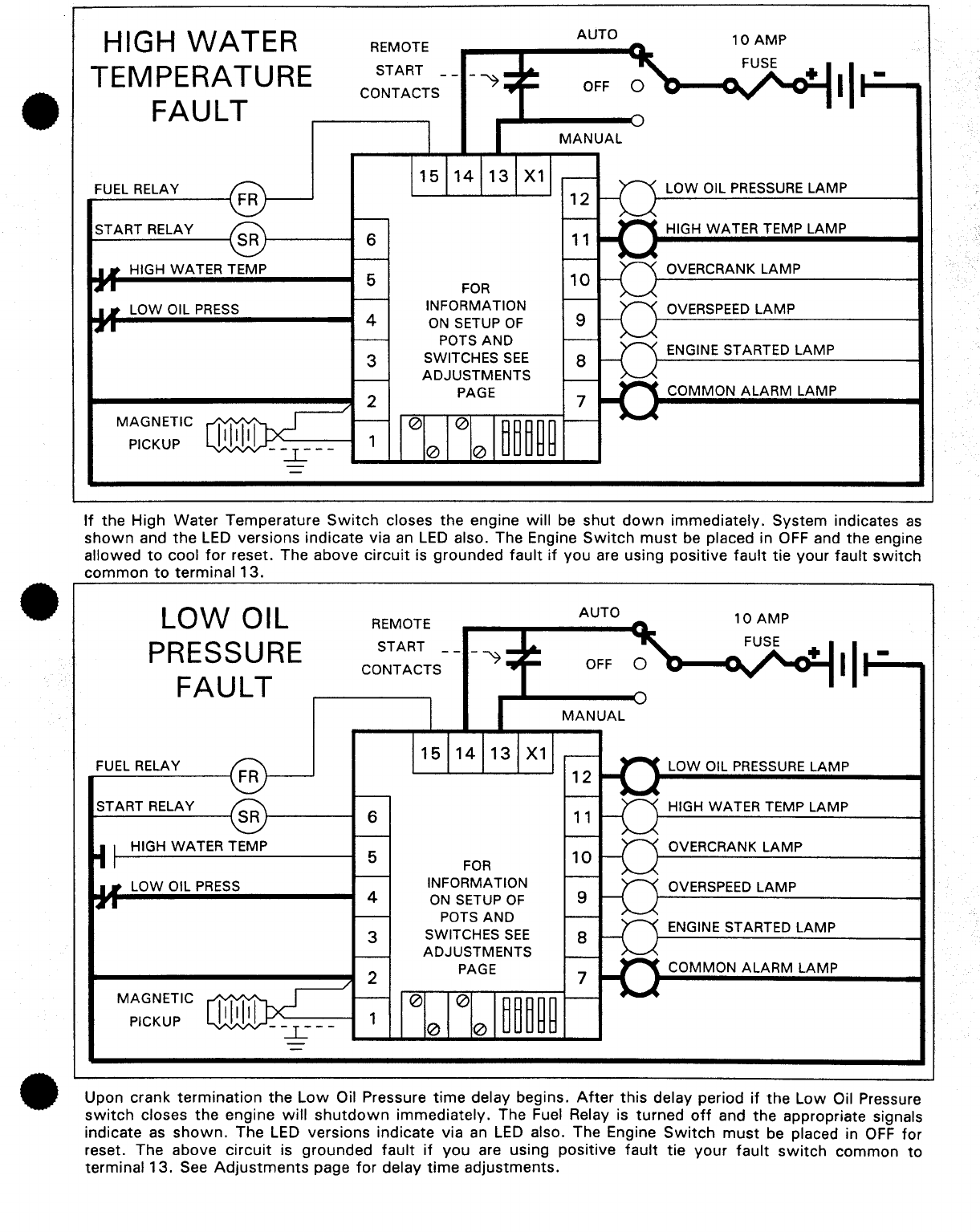
If
the High
Water
Temperature
Switch
closes
the
engine will be
shut
down
immediately. System indicates
as
shown
and
the
LED
versions indicate via
an
LED
also. The Engine
Switch
must
be placed in
OFF
and the engine
allowed
to
cool
for
reset. The above
circuit
is grounded
fault
if
you
are using
positive
fault
tie
your
fault
switch
common
to
terminal
13
.
LOW
OIL
PRESSURE
FAULT
FUEL RELAY
START RELAY
HIGH WATER TEMP
LOW OIL
PRESS
MAGNETIC
PICKUP
REMOTE
START
CONTACTS
6
5
4
3
1
15
14
13
X1
FOR
INFORMATION
ON SETUP
OF
POTS
AND
SWITCHES
SEE
ADJUSTMENTS
PAGE
AUTO
OFF
MANUAL
LOW OIL
PRESSURE
LAMP
HIGH WATER TEMP LAMP
OVERCRANK
LAMP
OVERSPEED LAMP
ENGINE STARTED LAMP
COMMON
ALARM
LAMP
Upon crank
termination
the
Low
Oil Pressure
time
delay begins.
After
this
delay period
if
the
Low
Oil Pressure
switch
closes
the
engine
will
shutdown
immediately. The Fuel Relay is
turned
off
and
the
appropriate signals
indicate
as
shown.
The
LED
versions indicate via
an
LED
also. The Engine
Switch
must
be placed in
OFF
for
reset. The above
circuit
is
grounded
fault
if
you
are using positive
fault
tie
your
fault
switch
common
to
terminal
13.
See
Adjustments
page
for
delay
time
adjustments.

NORMAL
SHUTDOWN
LAMP
TEST
88L/88N
ONLY
FUEL RELAY
START RELAY
HIGH WATER TEMP
LOW OIL
PRESS
MAGNETIC
PICKUP
REMOTE
START
CONTACTS
6
5
4
3
1
15
14
13
X1
FOR
INFORMATION
ON
SETUP
OF
POTS
AND
SWITCHES
SEE
ADJUSTMENTS
PAGE
AUTO
OFF
MANUAL
LOW OIL PRESSURE LAMP
HIGH WATER TEMP LAMP
OVERCRANK
LAMP
OVERSPEED
LAMP
ENGINE STARTED
LAMP
COMMON
ALARM
LAMP
To
stop
engine place
switch
in
the
OFF
position
and engine will
shut
down
immediately. The Fuel Relay
is
turned
off
and
the
unit
draws
no
power.
If
the
unit
is
an
LED
version lamp
test
may
be applied
as
shown
and
all LEDS
will
light. Since
the
output
system
is
totally
independent
of
the
signal
system
Lamp Test can
be
actuated at any
time
with
no
possibility
of
backfeed.
ADJUSTMENTS PAGE
TURN POTS CLOCKWISE
TO
INCREASE SETTING
POTS ARE
25
TURN
AND
CAN
NOT
BE
DAMAGED
BY EXCESS TURNS
1 2 3 4 5
1 2 3 4 5
SWITCH
5 ON FOR
OVERSPEED VERIFY
REDUCES TRIP SPEED
BY
13
PERCENT
CYCLES
SW1
SW2
SW3
1
OFF OFF OFF
SWITCH
4
2
OFF
ON
OFF
OFF -CYCLE
CRANK
3
ON
OFF OFF
4
ON ON
OFF
ON -SINGLE
CRANK
5
OFF
OFF
ON
6
OFF
ON ON
7
ON
OFF
ON
8
ON
ON
ON
DRILLING TEMPLATE
----------
2.65
.65
16.51
.35
8.89
.35
8.89
.35
8.89
.35
8.89
.35
8.89
.3
7.62
DRILLING
TEMPLATE 7.62
CENTER
PUNCH
2.8
DIRECTLY
--
THROUGH
71
·12
PAPER
1.3
33.02
ALL
HOLES
.25
6.35
DIA.
INCH
MM
•
•
•
•
•
•
EXTRA
FAULT
EXPANSION
FUEL RELAY
START RELAY
HIGH WATER TEMP
LOW OIL
PRESS
TIE FAULT
COMMONS TO
TERMINAL
13
MAG
PICKUP
EXTRA FAULT A
EXTRA FAULT B
REMOTE
START
CONTACTS
6
5
4
3
1
5
4
3
15
14
13
X1
FOR
INFORMATION
ON
SETUP
OF
POTS AND
SWITCHES
SEE
ADJUSTMENTS
PAGE
FEX3
2
AUTO
OFF
MANUAL
1
4
3
LOW OIL
PRESSURE
LAMP
HIGH WATER TEMP LAMP
OVERCRANK LAMP
OVERSPEED LAMP
ENGINE STARTED LAMP
COMMON
ALARM
LAMP
EXTRA FAULT A LAMP
EXTRA FAULT B LAMP
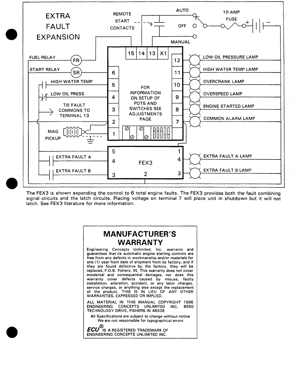
The FEX3 is
shown
expanding
the
control
to
6
total
engine
faults.
The FEX3 provides
both
the
fault
combining
signal
circuits
and
the
latch
circuits.
Placing
voltage
on terminal 7
will
place
unit
in
shutdown
but
it
will
not
latch. See FEX3 literature
for
more
information.
MANUFACTURER'S
WARRANTY
Engineering Concepts Unlimited, Inc. warrants and
guarantees
that
its automatic engine starting controls are
free
from
any defects in workmanship and/or materials for
one (1) year from date
of
shipment from its factory, and
if
they
are found defective
by
the factory, they will be
replaced, F.O.B. Fishers, IN. This
warranty
does
not
cover
incidental and consequential damages, nor does this
warranty
cover defects caused
by
misuse,
faulty
installation, alteration, accident, or any labor charges,
service charges, or anything else except the replacement
of
the product. THIS
IS
IN
LIEU
OF
ANY
OTHER
WARRANTIES,
EXPRESSED
OR
IMPLIED.
ALL MATERIAL
IN
THIS
MANUAL
COPYRIGHT
1996
ENGINEERING CONCEPTS UNLIMITED INC.
8950
TECHNOLOGY DRIVE,
FISHERS
IN
46038
All
Specifications are subject
to
change
without
notice
We are
not
responsible
for
typographical errors
®
ECU
IS
A REGISTERED TRADEMARK
OF
ENGINEERING CONCEPTS UNLIMITED INC.
This manual suits for next models
2
Table of contents


