manuals.online logo
Brands
  1. Home
  2. •
  3. Brands
  4. •
  5. Edwards Signaling
  6. •
  7. Speakers
  8. •
  9. Edwards Signaling Adaptatone Millennium Speaker 5553 Series Assembly instructions

Edwards Signaling Adaptatone Millennium Speaker 5553 Series Assembly instructions

© 2014 UTC Fire & Security Americas Corporation, Inc. 1 / 4 P/N 3101297-EN • REV 04 • ISS 12NOV14
5553 Series Adaptatone Millennium Speaker
Installation Sheet
Description
Edwards 5553 Series Adaptatone Millennium Speakers are
UL Listed audible signaling appliances that are designed to
accept system audio input levels of 25 or 70 VRMS. They are
designed to be used in conjunction with compatible control
equipment for high intelligibility reproduction of audible
emergency and protective signals as well as voice messages.
They comply with the requirements of UL Standard 1480. The
speakers are suitable for outdoor use with a UL 1480 wet
locations rated enclosure.
The speakers include a supervisory capacitor and are suitable
for installation in systems employing supervised circuitry
(25 V/ 70.7 V). Maximum supervised circuit voltage is 24 VDC.
Speaker direction and the output level are easily adjustable.
Output wattage is easily adjusted by an internal rotary switch.
Additionally, the Adaptatone series are UL Listed as audible
signal appliances for use in the hazardous locations shown in
Table 1.
Table 1: Hazardous locations specifications [1]
Model [2]
Rated
ambient
Hazardous locations Temp. code
5553
-25/70-G
5553
-25/70-R
40°C Class I, Div. 2, Groups A, B,
C, D
T4A (120˚C)
Class II, Div. 2, Groups F, G
Class III, Div. 1 and 2
T5 (100˚C)
[1]
Hazardous locations and variable ambient conditions apply only
where UL listings are accepted.
[2] The letter suffix in model numbers indicates the color.
G = Green, R = Red.
Figure 1: Speaker dimensions
Installation
The Adaptatone speaker may be mounted to any flat surface
or may be used as a freestanding unit mounted to a rigid pipe.
The device must be installed in accordance with the latest
edition of the National Electrical Code or other regulations
applicable to the country and locality of installation and by a
trained and qualified electrician.
WARNINGS
•Explosion hazard. Substitution of components may impair
suitability for Class I, Division 2.
•Explosion hazard. Do not disconnect equipment unless
power has been switched off or the area is known to be
nonhazardous.
•Fire and shock hazard. Wire the unit only as described on
this installation sheet.
Note: This apparatus is suitable for use in Class I, Division 2,
Groups A, B, C and D, Class II, Division 2, Groups F and G,
Class III, Division 1 and 2.
1. Mount the speaker as shown in Figure 2, using one of the
following methods.
Flat surface mounting. Secure the unit to the mounting
surface using the four mounting holes in the mounting
plate on the rear of the signal box. Use #10 × 3 in.
(76 mm) wood screws (furnished loose) or other hardware
(not supplied) suitable for the mounting surface.
— or —
2.0 in.
(51 mm)
7.5 in.
(191 mm)
8-7/8 in.
(225 mm)
8-1/4 in.
(210 mm)
13 in.
(330 mm)
2 / 4 P/N 3101297-EN • REV 04 • ISS 12NOV14
Rigid pipe mounting. Loosen the four cover screws from
the signal box and lift off the signal box cover.
Note: The cover screws are captive. Do not remove them
from the cover.
Remove the center knockout in the lower wall of the box
and mount the box to a 1/2 in. (12.7 mm) conduit pipe
using a suitable connector.
2. Install the wires through a knockout hole in the bottom of
the box from a raceway that, with its connections to the
1/2 in. (12.7 mm) conduit knockout hole, is approved for
the same degree of protection and enclosure type needed
by the application.
3. Wire as follows, referring to Figure 3 and Figure 4:
a. Connect audio in (+) and audio in (−) to the AUDIO
INPUT terminals of the two-position terminal block on
the faceplate (Figure 3).
Observe the polarity on the faceplate label. Shielded
cable is recommended.
b. When connecting multiple speakers or supervised
circuits, connect the wires leading to the next signal or
end-of-line resistor on the same INPUT/OUTPUT
terminals (+) and (−) on the two-position terminal
block as shown in Figure 4. Again, polarity must be
observed.
4. Adjust the voltage/wattage level by turning the power tap
selection switch located on internal faceplate. See Table 2
for power tap selection settings.
WARNINGS
•To ensure integrity of the enclosure: Ensure the cover
gasket (P/N P-007549-0069)is adhered into groove
at the cover perimeter before replacing the signal box
cover.
•Ensure that the four collar gaskets
(P/N P-041930-0362) are in place on each cover
screw before securing the signal box cover (Figure 2).
When securing the cover, start the screws by hand,
making sure they are threaded into tapped holes in
the housing bosses before securing with a
screwdriver. Torque the signal box cover screws to a
minimum of 20 in-lbs. This ensures the required tight
fit.
5. Tightly secure the signal box cover using the four retained
cover screws.
6. Torque the signal box cover screws (Figure 2) to a
minimum of 20 in-lbs.
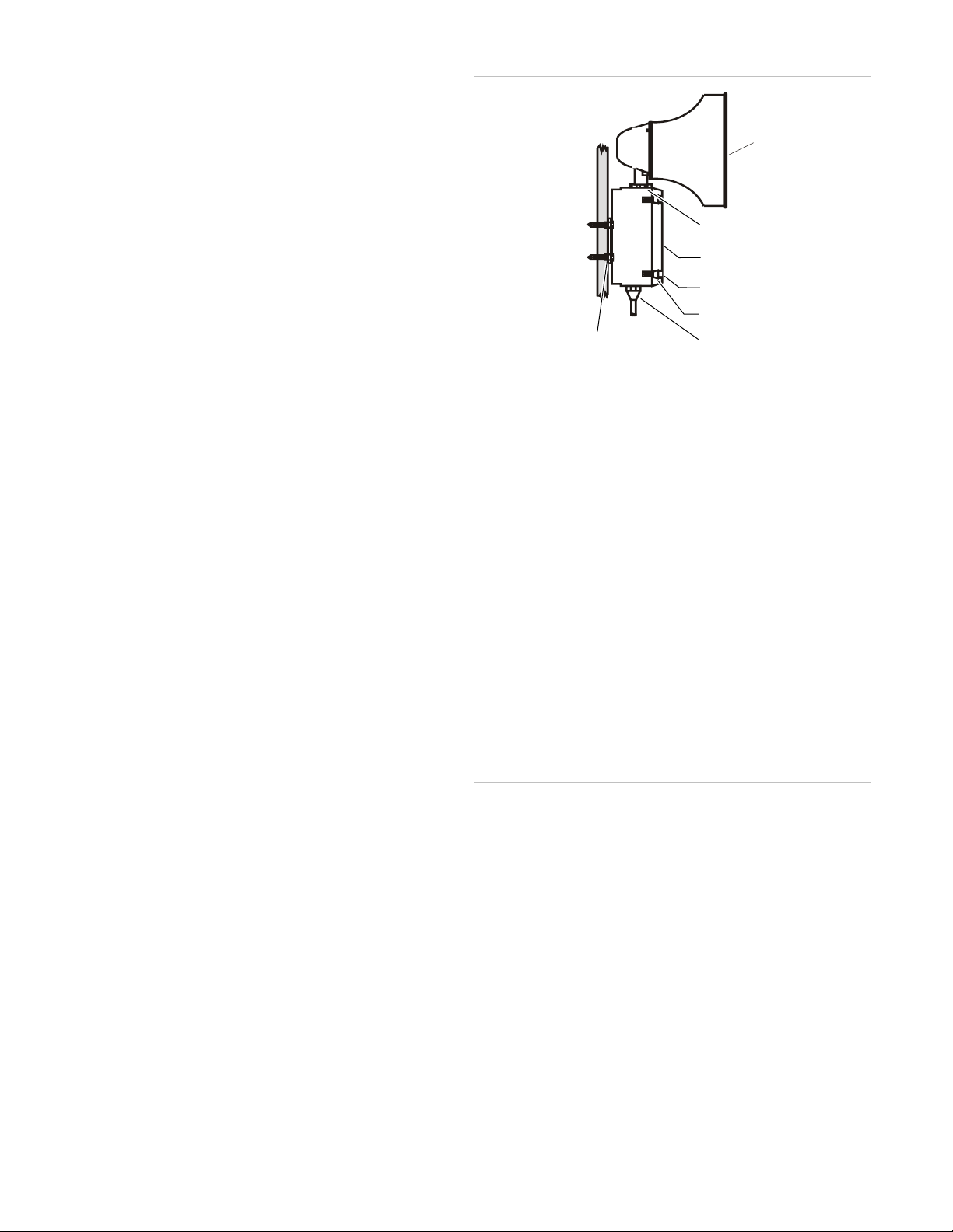
Figure 2: Speaker mounting
WARNING: To ensure the integrity of the Adaptatone
assembly when adjusting the speaker direction, make sure
threads in the enclosure remain fully engaged and do not
turn the speaker more than 360 degrees from the original
factory installed position.
7. To adjust speaker direction, loosen the large star nut
(Figure 2) and turn the speaker to the approximate desired
position.
8. Regardless of the speaker direction adjustment, it is
important that the star nut be tightened wrench-tight to
ensure the speaker position is maintained securely.
WARNING: High volume may cause harm to personnel in
close proximity.
9. Verify operability.
Maintenance
WARNING: Ensure that power is disconnected before cleaning
inside of unit.
Examine the unit semi-annually for accumulation of dirt. Clean
if necessary.
The Adaptatone speaker should be tested annually or as
required by the authority having jurisdiction to ensure
continuous service.
Speaker
Large star nut to
adjust speaker
direction
Signal Box
(4X) Cover
screws
(4X) Collar
gaskets
Raceway and connections
(not supplied) to 1/2 in.
(12.7 mm) knockout hole
(4X) #10 x 3 in. (76 mm)
screws or other hardware
suitable for the mounting surface
P/N 3101297-EN • REV 04 • ISS 12NOV14 3 / 4
Figure 3: Wiring a single 5553 series speaker (non supervised)
Table 2: Power tap selector switch
Switch position
Impedance 25 V line SPL dB(A) at 10 ft. 70 V line SPL dB(A) at 10 ft.
1
5.0 K - - 0.9 W 93
2
2.5 K - - 1.8 W 96
3
1.3 K 0.48 W 91 3.8 W 98
4
666 0.94 W 93 7.5 W 101
5
333 1.8 W 96 15.0 W 103
6
89 7.5 W 101 Do not use on 70 V
7
45 15.0 W 103
Figure 4: Wiring multiple 5553 series speakers and/or supervised circuits
Caution:
To ensure proper supervision of connections, do not use
looped wires under the terminal screws. Break each wire run. Use both
sides of the terminal screws as shown.
Note:
To conform to UL requirements, wires must be connected as
shown
in the wiring diagram. Wire size: 12 to 18 AWG (1.0 to
4.0
mm²).
From amplifier
1/2 in. (12.7 mm) conduit entries
Power tap
selection switch
(see Table 2)
From supervised
or non supervised
amplifier
1/2 in. (12.7 mm) conduit entries
To next speaker
or end-of-line
resistor
Power tap
selection switch
(see Table 2)
4 / 4 P/N 3101297-EN • REV 04 • ISS 12NOV14
Specifications
Weight
Speaker/amplifier
9 lb. (4.1 kg)
Hazardous
locations [1]
Ambient temp
−13˚F to +104˚F (−25˚C to +40˚C)
Non
hazardous locations
Variable ambient temp
−40˚F to +151˚F (−40˚C to +66˚C)
Frequency
range 400 Hz to 4,000 Hz
[1] Per ANSI/ISA 12.12.01
Regulatory information
North American
standards
ANSI/ISA 12.12.01, UL 464, UL 1480
Contact information
For contact information, see www.edwardssignaling.com.

Other Edwards Signaling Speakers manuals

Edwards Signaling 5553 Series Owner's manual

Edwards Signaling

Edwards Signaling 5553 Series Owner's manual

Edwards Signaling 5531M Assembly instructions

Edwards Signaling

Edwards Signaling 5531M Assembly instructions

Popular Speakers manuals by other brands

Musica M2525LCR install guide

Musica

Musica M2525LCR install guide

JBL S3100 L Technical manual

JBL

JBL S3100 L Technical manual

Dcm Surroundscape Setup & operating instruction

Dcm

Dcm Surroundscape Setup & operating instruction

JBL LSR owner's manual

JBL

JBL LSR owner's manual

Soyntec Voizze 120 Series user manual

Soyntec

Soyntec Voizze 120 Series user manual

Barefoot Sound MicroMain45 user manual

Barefoot Sound

Barefoot Sound MicroMain45 user manual

Amazon Echo quick guide

Amazon

Amazon Echo quick guide

Philips AW9000 quick start guide

Philips

Philips AW9000 quick start guide

Anchor AN-130+ owner's manual

Anchor

Anchor AN-130+ owner's manual

Polk Audio LSi 25 owner's manual

Polk Audio

Polk Audio LSi 25 owner's manual

Amazon B00GUTY3DK instruction manual

Amazon

Amazon B00GUTY3DK instruction manual

PURE Jongo T2 user guide

PURE

PURE Jongo T2 user guide

Element ESB205 instruction manual

Element

Element ESB205 instruction manual

Naxa NDS-1236 instruction manual

Naxa

Naxa NDS-1236 instruction manual

LENCO Xemio-669 user manual

LENCO

LENCO Xemio-669 user manual

JAMO DS3 manual

JAMO

JAMO DS3 manual

DNH H760EExeN installation manual

DNH

DNH H760EExeN installation manual

Fugoo Element F6ELKS01 user manual

Fugoo

Fugoo Element F6ELKS01 user manual

manuals.online logo
manuals.online logoBrands
  • About & Mission
  • Contact us
  • Privacy Policy
  • Terms and Conditions

Copyright 2025 Manuals.Online. All Rights Reserved.