3
Warning! The electrical connection of the device
can be carried out only by qualied personnel. The
incorrect installation may result in electric shock or
re. Before making the electrical connections, make
sure the power supply has been turned o.
!
Mounting
The device has degree of protection IP20, and is therefo-
re suitable for use in dry interior rooms. The support EK-
SMG-35 allows the mounting on 35 mm rail in boards or ca-
binets for electrical distribution.
a) Insert the mounting support into the appropriate shaped prole of the
interface
c) Once fastened, connect the bus line, the inputs and the outputs
b) Place the support clamping tooth on the top edge of the mounting
rail and rotate device and support towards the guide until it completely
engages
Conguration and commissioning
Conguration and commissioning of the device re-
quire the use of the ETS® (Engineering Tool Software)
program V4 2.0 or later releases. These activities must
be carried out according to the design of the building au-
tomation system done by a qualied planner.
Conguration
For the conguration of the device parameters the corre-
sponding application program or the whole ekinex®pro-
duct database must be loaded in the ETS program. For
detailed information on conguration options, refer to the
application manual of the device available on the website
www.ekinex.com.
Note. The conguration and commissioning of KNX
devices require specialized skills. To acquire these
skills, you should attend the workshops at KNX cer-
tied training centers.
i
Product
code
Application
software
(## = release)
Comm.
objects
(max nr.)
Group
adresses
(max nr.)
EK-CE2-TP
APEKCE2TP##.knxprod
196 196
Commissioning
For commissioning the device the following activities are
required:
• make the electrical connections as described above;
• turn on the bus power supply;
• switch the device operation to the programming mode
by pressing the programming pushbutton located on
the front side of the housing. In this mode of operation,
the programming LED is turned on;
• download into the device the physical address and the
conguration with the ETS® program.
At the end of the download the operation of the device
automatically returns to normal mode; in this mode the
programming LED is turned o. Now the bus device is
programmed and ready for use.
Reset of the device
To reset the device remove the bus connection by ex-
tracting the bus terminal from its seat. Keeping pressed
the programming pushbutton, reinsert the bus terminal in
his seat; the programming LED blinks fast. Release the
programming button and remove the bus terminal again;
the reset was carried out. Now you need to address and
congure again the device via ETS.
Warning! The reset restores the device back to the
state of delivery from the factory. The address and
the value of the parameters set during conguration
will be lost.
!
Marks
• KNX
• CE: the device complies with the Low Voltage Directi-
ve (2014/35/EU) and the Electromagnetic Compatibili-
ty Directive (2014/30/EU). Tests carried out according
to EN 50491-5-1:2010 and EN 50491-5-2:2010
Maintenance
The device is maintenance-free. To clean use a dry cloth.
It must be avoided the use of solvents or other aggressive
substances.
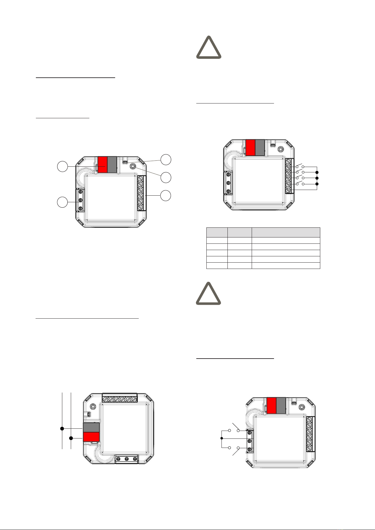
Block Mark Connection
7 OUT1 Output Relais 1
8 COM Output common
9 OUT2 Output Relais 2
Disposal
At the end of its useful life the product descri-
bed in this datasheet is classied as waste
from electronic equipment in accordance with
the European Directive 2012/19/EU (WEEE
recast), and cannot be disposed together with
the municipal undierentiated solid waste.