Electra Meccanica SOLO User manual

EMERGENCY
RESPONDERS GUIDE


1
TABLE OF CONTENTS
SAFETY INFORMATION 2
Important Safety Instructions 2
About This Guide 2
About Vehicle References 2
Symbols Glossary 3
IDENTIFYING THE SOLO 4
Exterior 4
Interior 5
Vehicle Identification Number (VIN) 6
IMMOBILIZING/STABILIZING THE VEHICLE 7
Drive System Status (READY Mode) 7
Shifting Into Neutral 8
Applying the Electronic Parking Brake (EPB) 9
Chocking the Wheels 11
ELECTRICAL SYSTEM INFORMATION 12
High-Voltage Components 12
High-Voltage Warning Labels 13
High-Voltage Batteries 14
12-Volt Battery 15
High-Voltage Cables 17
Drive Motor 18
OPENING THE VEHICLE 19
Hood 19
Trunk 19
Power Windows 21
Remote Transmitter 22
DISABLING THE POWER 23
Required Equipment 23
Using the Key Switch 24
Disconnecting the Charge Cable 25
Disabling the 12-Volt System 26
Disabling the High-Voltage System 28
RESCUE OPERATIONS 30
Cutting the Vehicle 30
Lifting the Vehicle 32
Vehicle Fires 33
Submerged Vehicles 33
POST-INCIDENT VEHICLE INSPECTION 34
Inspection Recommendations 34
What to Inspect For 34
After Inspection 35
MOVING THE VEHICLE 36
Moving Off the Road 36
Transporting the Vehicle 37
Using the Recovery Eye 38
Vehicle Weight Information 40
STORAGE AND ISOLATION 41
Storing Damaged Vehicles 41
Methods of Isolation 41
2
SAFETY INFORMATION
SAFETY INFORMATION
Important Safety Instructions
This guide describes first response operations and important safety-related warnings that must be followed when
handling this vehicle in an emergency situation.
This electric vehicle is equipped with a high-voltage battery pack. Failure to follow recommended practices during
emergency responses can cause death or serious personal injury.
Please read this guide in advance to understand the features of this vehicle and to help you deal with incidents
involving this vehicle. Follow the procedures to help ensure a safe and successful first response operation.
About This Guide
This guide covers the SOLO vehicle for models manufactured in 2021 or newer.
This manual may be periodically updated. If you are not viewing this manual on the official ElectraMeccanica website,
go to https://electrameccanica.com/firstresponders or https://electrameccanica.com to ensure you have the most
recent version.
About Vehicle References
The terms Left or Right refer to the driver’s left or right while sitting in the vehicle.
LEFT SIDE
L
RIGHT SIDE
R

3
SAFETY INFORMATION
Symbols Glossary
The following symbols and words used within this manual call your attention to specific types of hazards and what to do
to avoid or reduce them.
The following cautionary symbols may be found on labels throughout the vehicle.
Indicates a hazard with a high level of risk which will result in serious injury or death
Indicates a hazard that could result in injury or death
Indicates a hazard that could result in property or vehicle damage
Note: Indicates additional information, hints, and tips.
Symbol Definition
Warning
Risk of electric shock; use caution
Risk of electric shock; use caution
Refer to instructions/manual
DANGER
WARNING
CAUTION

4
IDENTIFYING THE SOLO
IDENTIFYIN G THE SOLO
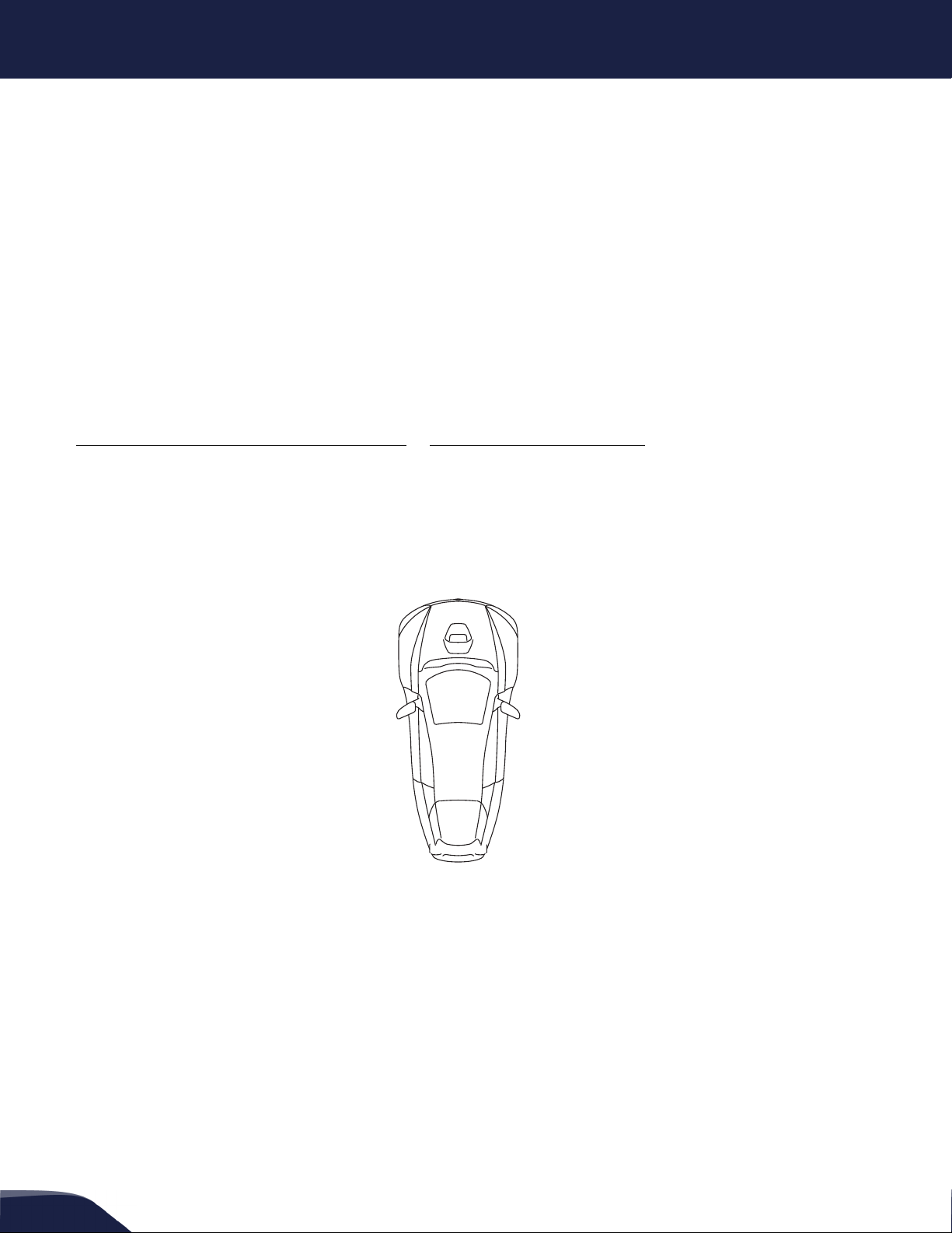
Exterior
The SOLO is a three-wheeled, single-passenger, all-electric vehicle. The exterior can be distinguished by its unique
badging.
5
IDENTIFYING THE SOLO
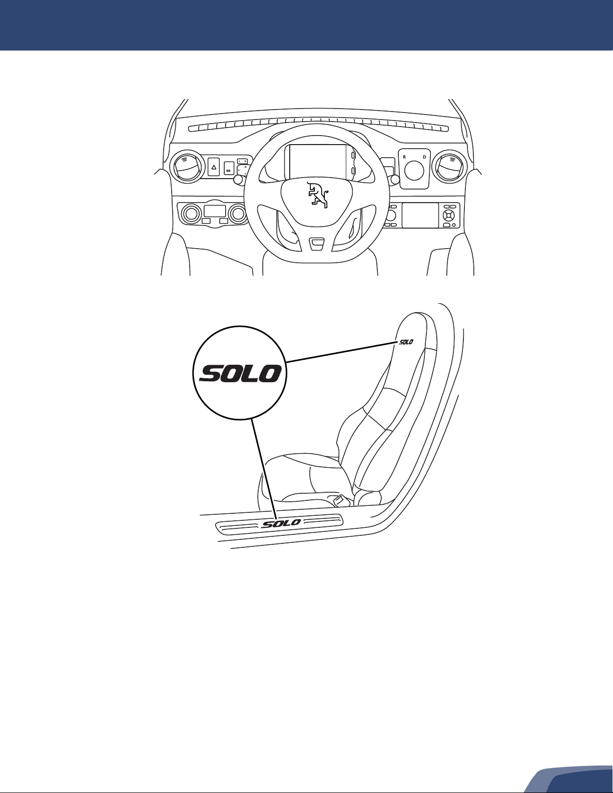
Interior
The SOLO can be identified from the interior by its unique dashboard layout and instrument cluster display screen.
Both the seat and the rocker panels in the door frames have SOLO badging.
MIRROR


7
IMMOBILIZING/STABILIZING THE VEHICLE
IMMOBILIZING/STABILIZING THE VEHICLE
Drive System Status (READY Mode)
Note: This vehicle will creep forward or backward when the brakes are not applied and the Drive Mode is in D (Drive) or
R(Reverse).
The READY indicator on the instrument cluster display signifies that the drive system is powered on and available.
To put the vehicle into READY mode:
1. Close both vehicle doors and fasten the seat belt.
2. Insert the key into the key switch. See “Using the Key Switch”, page 24.
3. Press down on the brake pedal until it is fully depressed and hold it down.
4. Without moving the steering wheel, turn the key to the ON position. The display will show the ElectraMeccanica
logo, then load the instrument cluster display. All indicators will flash briefly.
Note: Do not move the steering wheel while cycling the key switch from OFF to ON, as this can result in a fault. If this
occurs, turn the key switch to OFF, then cycle to ON without touching the steering wheel.
5. Ensure that the Drive Mode Selector is set to N(Neutral). See “Shifting Into Neutral”, page 8.
Note: If the Drive Mode is not currently set to N (Neutral), you will be prompted to do so by the display.
6. Turn the key to clockwise past the ON position to the START position.
Note: If the brake pedal is not currently pressed, you will be prompted to do so by the display.
7. Allow the key to return to the ON position. The READY indicator will illuminate on the instrument cluster display.
The vehicle is now ready to be driven.
Note: The Electronic Parking Brake (EPB) will disengage automatically when the vehicle is in READY mode, the Drive
Mode Selector is in D (Drive) or R (Reverse), and the accelerator is pressed.
To power down the drive system, turn the key to the OFF position.
Note: The EPB will automatically engage when the key switch is turned to the OFF position.
SWITCH
SET
N
15:09
06
75
96%
Mph
82˚
F
TRIP
miles
miles
ChargePower
Power
Regen
Charge
READY
8
IMMOBILIZING/STABILIZING THE VEHICLE
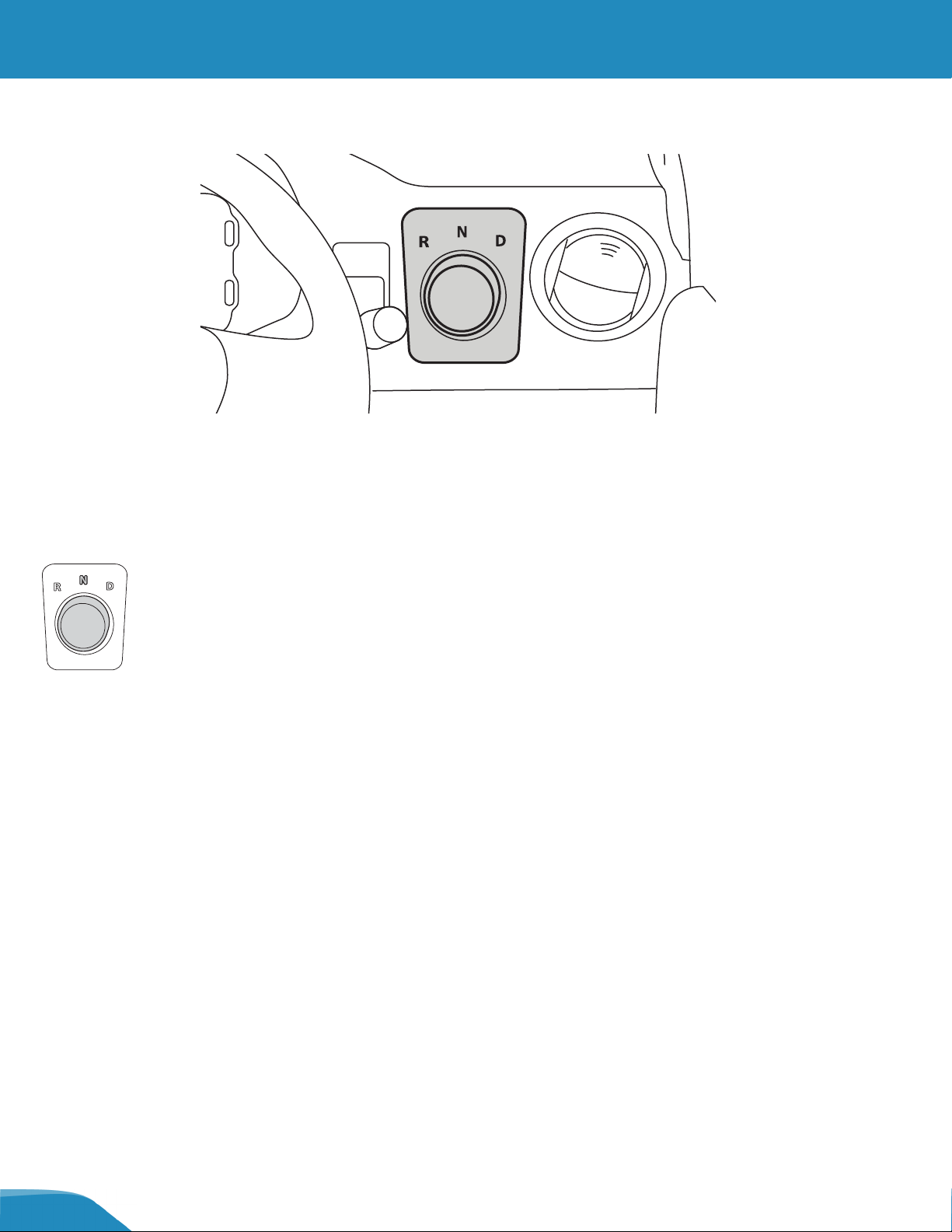
Shifting Into Neutral
The Drive Mode Selector is a three-position dial on the dashboard. When the key switch is ON, the Drive Mode
Selector can be used to set the desired direction of the vehicle:
•R - Reverse
•N - Neutral (Use when starting, parking, or transporting the vehicle)
•D - Drive
The current selection is illuminated on the dial, and is also indicated on the instrument cluster display.

9
IMMOBILIZING/STABILIZING THE VEHICLE
Applying the Electronic Parking Brake (EPB)
The EPB has both manual and automatic functions. It is manually controlled by a rocker switch on the dashboard, to
the right of the steering wheel.
When the EPB is engaged either manually or automatically, the EPB indicator will illuminate on the instrument
cluster display.
Note: The EPB can only be engaged or disengaged manually when the vehicle's speed is less than 2 mph (3 km/h) and the
key switch is in the ON position.
Note: The EPB can be engaged in any Drive Mode Selector position.
Using the EPB manually
To engage the EPB manually:
1. Ensure that the vehicle is moving at less than 2 mph (3 km/h) and the key switch is in the ON position. See “Using
the Key Switch”, page 24.
2. Pull out the EPB switch.
To disengage the EPB manually:
1. Ensure that the vehicle is moving at less than 2 mph (3 km/h) and the key switch is in the ON position. See “Using
the Key Switch”, page 24.
2. When in READY mode: Press the brake pedal, then push in the EPB switch. See “Drive System Status (READY
Mode)”, page 7.
3. When not in READY mode: Press the brake pedal, then push and hold the EPB switch for 30 seconds.
Note: If the 30-second long push of the EPB switch is interrupted, you must repeat it for the full 30 seconds.
Note: While holding the EPB switch, the “Start Vehicle” system message will appear on the instrument cluster display.
P

10
IMMOBILIZING/STABILIZING THE VEHICLE
EPB Maintenance Mode
Use caution when disengaging the EPB, as the vehicle will be free-rolling. Be aware that the
vehicle could roll if it is not on a level surface.
Pushing the vehicle with wheels on the ground should only be done for very short distances, as
prolonged rolling (e.g. towing with wheels on the ground) can cause heat damage to the drive
motor system and generate high voltages in the electrical system.
The EPB has a special Maintenance Mode, which allows it to remain disengaged while the vehicle is OFF, overriding
the automatic function until the vehicle is turned ON again.
When the EPB Maintenance Mode is engaged, a system message will be displayed on the
instrument cluster display.
To enter EPB Maintenance Mode, first disengage the park brake manually. When the vehicle is NOT started (READY
message is NOT illuminated on the dashboard):
1. Press and hold the brake pedal.
2. Push in and hold the EPB switch continuously for 30 seconds. The EPB indicator will illuminate on the instrument
cluster display.
Note: If the 30-second long push of the EPB switch is interrupted, you must repeat it for the full 30 seconds.
Then enter Maintenance mode with the following steps:
1. Press and hold the brake pedal.
2. Push in and hold the EPB switch continuously for 30 seconds. The EPB indicator will illuminate on the instrument
cluster display.
Note: If the 30-second long push of the EPB switch is interrupted, you must repeat it for the full 30 seconds.
3. Turn the key switch to the OFF position.
To exit Maintenance Mode, use either option:
•Turn the key switch ON, press the brake pedal, then pull out the EPB switch.
•Turn the key switch ON, then OFF. Once the vehicle is keyed ON, the automatic functions of the EPB will
resume, and it will engage automatically when the key switch is turned OFF.
WARNING
CAUTION
Park Brake
Maintenance Mode
11
IMMOBILIZING/STABILIZING THE VEHICLE
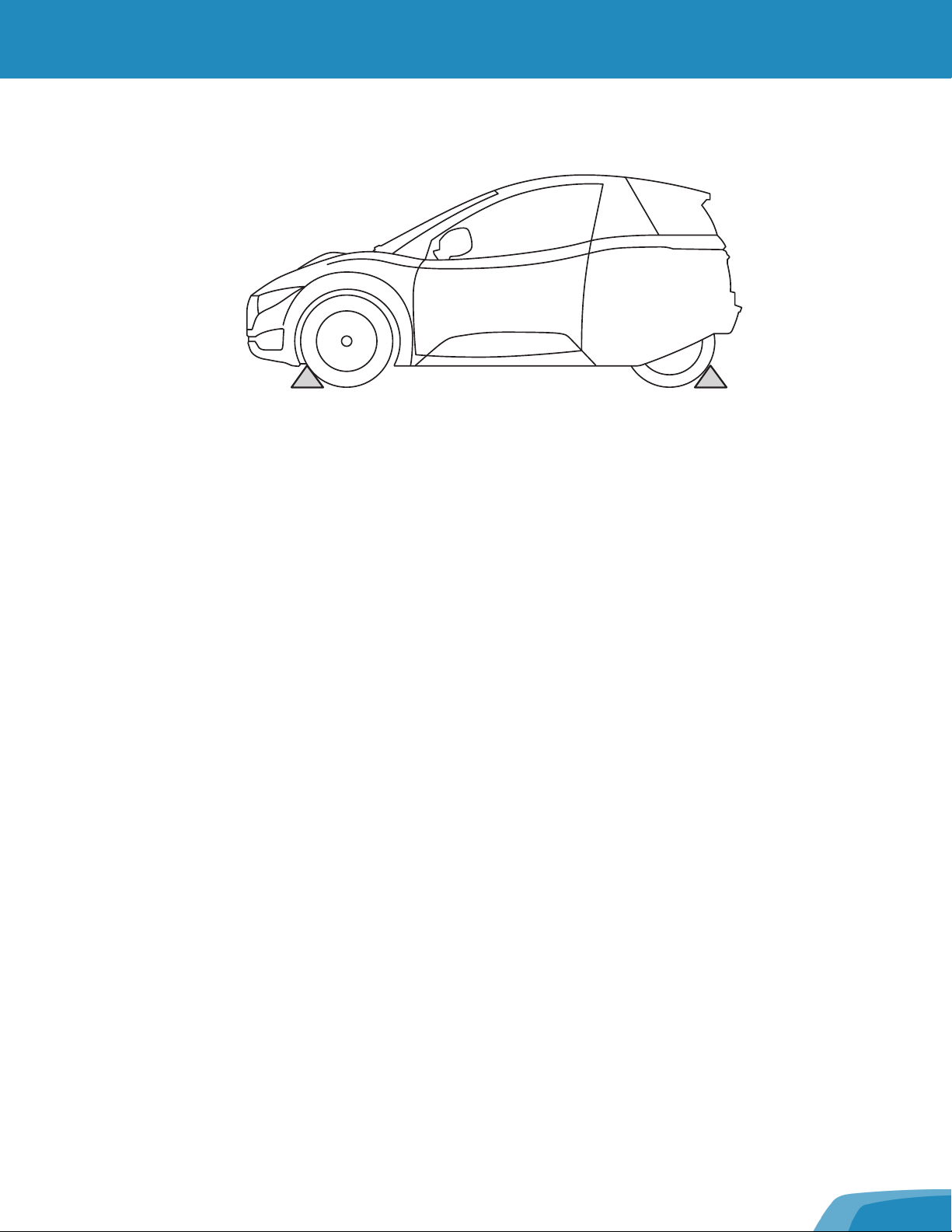
Chocking the Wheels
To help prevent the vehicle from moving, always chock all three wheels before attempting extraction procedures.
•Electric vehicles run and drive silently, so never assume they are powered off.
•When the Drive Mode Selector is in D (Drive) or R (Reverse), this vehicle will creep forward or backward while the
drive system is powered on and the brakes are not engaged.
12
ELECTRICAL SYSTEM INFORMATION
ELECTRICAL SYSTEM IN FORMATION
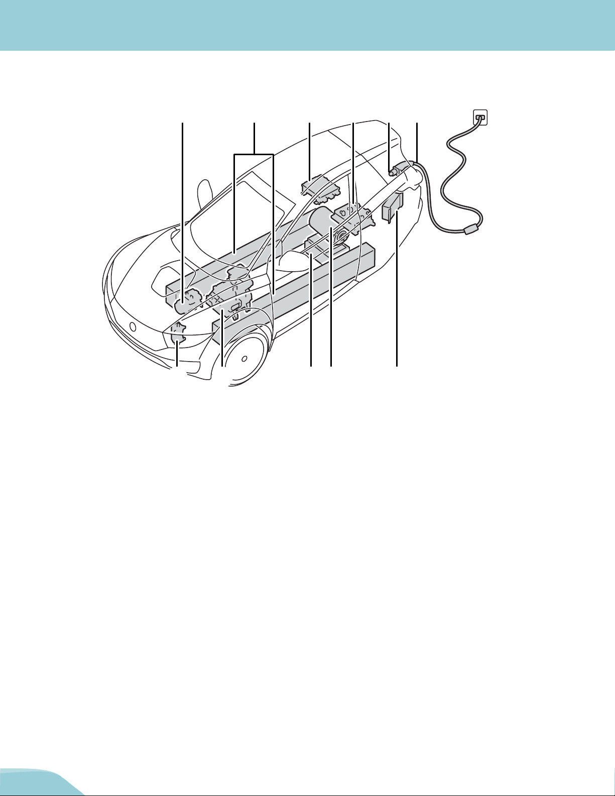
High-Voltage Components
1. A/C compressor
2. High-voltage batteries
3. On-board charger
4. Powertrain controller
5. Charging port
6. Charging cable
7. DC/DC converter
8. Drive motor
9. High-voltage distribution box
10.Cabin heater
11. Battery heater
2 31 4 5 6
71011 89

13
ELECTRICAL SYSTEM INFORMATION
High-Voltage Warning Labels
Not all high-voltage components are labeled. Always wear appropriate PPE when cutting the
vehicle. Failure to do so can result in death or serious injury.
Illustrated above are examples of some of the high-voltage warning labels that can be found on high-voltage
components within the vehicle. These labels are one way to quickly identify potential electrical hazards. For your
safety, always follow all cautions and instructions on warning labels.
Labeled high-voltage components include (but are not limited to):
•High-voltage batteries (both tubes)
•DC/DC converter
•High-voltage distribution box
•A/C compressor
WARNING
High Voltage
Follow Lockout Procedure
Before Removing The Cover
WARNING
14
ELECTRICAL SYSTEM INFORMATION
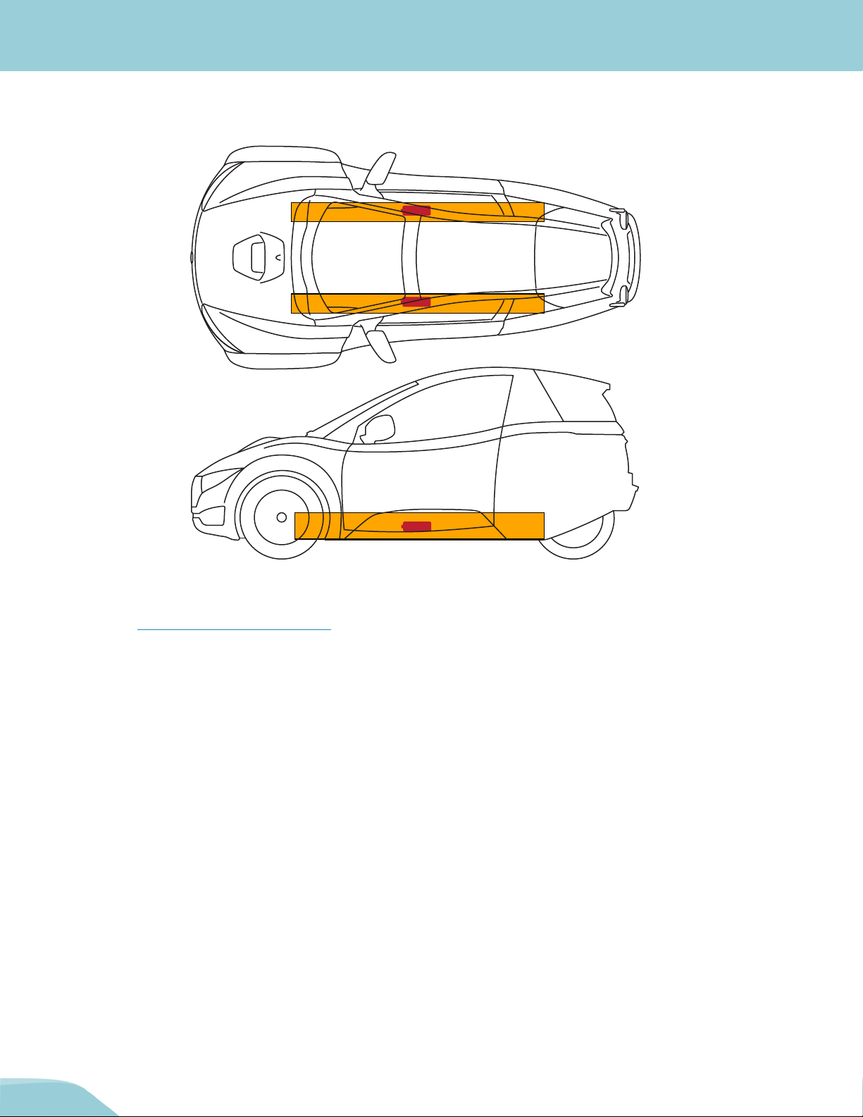
High-Voltage Batteries
The 144V lithium-ion batteries are encased and mounted under the vehicle floor.
When using lifting or rescue tools, use caution and never breach a high-voltage battery case. For proper lifting
procedures, see “Lifting the Vehicle”, page 32.
Li-ion
Li-ion
Li-ion
15
ELECTRICAL SYSTEM INFORMATION
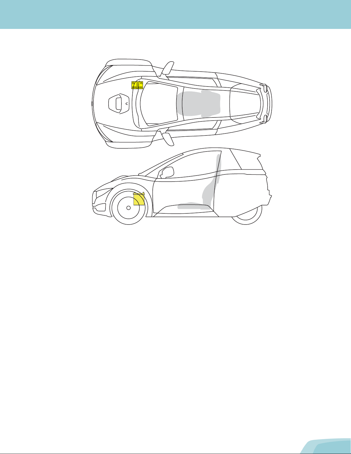
12-Volt Battery
The 12V battery is located at the right front of the chassis, to the right of the accelerator pedal. This battery powers all
of the standard low-voltage electronics in the vehicle. It also powers the high-voltage distribution box, which controls
high-voltage current within the high-voltage components (e.g. drive motor, powertrain controller).
16
ELECTRICAL SYSTEM INFORMATION
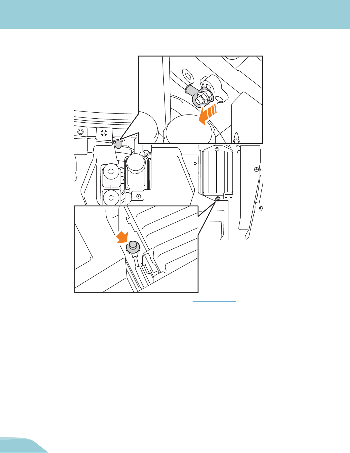
Locating the 12V battery terminals
The vehicle’s 12V battery terminals are located under the hood (see “Hood”, page 19) as follows:
1. The positive (+) terminal is located behind the fluid reservoirs. Remove the cap to expose the terminal.
2. The negative (-) terminal is located near the base of the fuse box.
1
2
17
ELECTRICAL SYSTEM INFORMATION
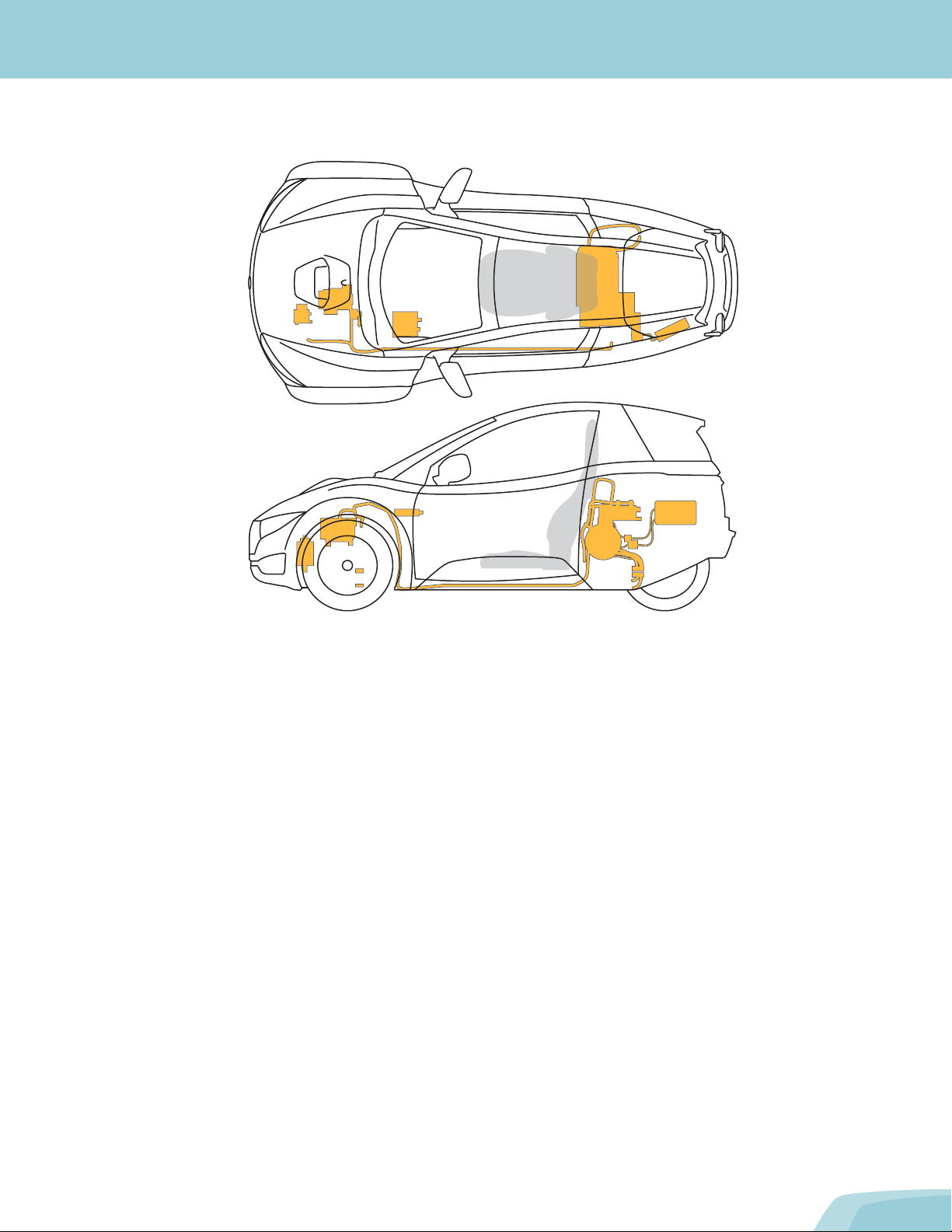
High-Voltage Cables
High-voltage cables are colored orange for easy identification.

18
ELECTRICAL SYSTEM INFORMATION
Drive Motor
The drive motor (1) is located near the rear wheel of the vehicle. This component receives 3-phase alternating current
(AC) and converts it into propelling energy (torque), used to power the wheels.
1
Other manuals for SOLO
1
Table of contents


