Electro motive tec3r Guide

Product Installation Manual
& User’s Guide
V1.11
Electromotive, Inc 703-331-0100
9131 Centreville Road 703-331-0100 fax
Manassas,VA 20110 support@electromotive.com

Tec3r Manual Version 1.11 - Page 2 - ©2017 Electromotive, Inc.
Table of Contents
Term and Conditions....................................................................................7
Electromotive, Inc. Limited Product Warranty......................................................................... 7
New Product Limited Warranty:..............................................Error! Bookmark not defined.
If You Need Warranty Service:................................................................................................. 7
Out-of-Warranty Product Repair .............................................................................................. 7
Third Party Products and Parts: ................................................................................................ 7
Warranty Exclusions................................................................................................................. 7
Determinations:......................................................................................................................... 8
Disclaimer of Implied Warranties:............................................................................................ 8
Exclusion of Damages: ............................................................................................................. 8
Forward..................................................................................................9
A. Installing the Tec3-r System.........................................................10
A.1. How it All Works: The Two Pages You Need to Read ........................10
A.2. Pre-Installation Checklist.......................................................................11
A.3. Mounting the Main Computer and DFU ..............................................12
A.4. Trigger Wheel and Sensor Installation .................................................13
A.4.a. Crankshaft Trigger Installation for 60(-2) Tooth Wheel............................................. 14
A.4.b. Magnetic Crank Sensor Installation............................................................................ 14
A.4.d. Verifying Trigger Wheel Timing................................................................................ 16
A.4.e. Camshaft- & Distributor-Mounted Trigger Setups ..................................................... 18
A.4.f. Full Sequential Applications –Cam Synchronization................................................. 18
A.4.g. TDC Tooth Setup Software Adjustment Parameters .................................................. 19
A.5. Wiring the Tec3-r....................................................................................22
A.5.a. Tec3-r Main Power Connections............................................................................... 22
A.5.b. Power Harness Installation.......................................................................................... 22
A.5.c. Wiring the Fuel Injectors............................................................................................. 23
A.5.d. Wiring the DFU’s........................................................................................................ 24
A.5.e. Wiring the Engine Sensors.......................................................................................... 24
B. Tuning Guide .................................................................................25
Introduction ......................................................................................................25
B.1. Adjusting the Timing Advance...............................................................25
B.2. Establishing Proper Starting Enrichments...........................................26
B.3. Getting the Engine to Idle.......................................................................27
B.4. Establishing Proper Acceleration Enrichments ...................................27
B.5. Adjusting the VE Table...........................................................................28
B.6. Using TPS/MAP Blend............................................................................29
B.7. Tuning for Cold Engines and Cold Weather........................................29
B.8. Tuning the Idle Air Control Motor........................................................30
B.8.a Configuring the New Electromotive Idle Speed Control ............................................ 30
B.8.b. Idle Speed primer ........................................................................................................ 31
B.8.c Getting Started.............................................................................................................. 31
B.8.d Error Sensitivity ........................................................................................................... 32

Tec3r Manual Version 1.11 - Page 3 - ©2017 Electromotive, Inc.
B.8.e. RPM Rate-of-Change Sensitivity................................................................................ 32
B.8.f. Wiring a 2-wire IAC:................................................................................................... 33
B.8.g. Wiring a 3-wire IAC: .................................................................................................. 34
B.9. Tuning the Knock Control......................................................................34
B.10. Using the Injector Trims.......................................................................34
B.11. Using the Ignition Advance Trims.......................................................35
B.12. Tuning the EGO Sensor........................................................................35
C. Direct Fire Units (DFU’s) .............................................................36
Introduction ......................................................................................................36
C.1. Wiring the DFU’s ....................................................................................36
C.2. DFU to Spark Plugs.................................................................................37
C.3. Spark Plug Wire Routing .......................................................................40
C.3.a. Common Engine Setups .............................................................................................. 40
C.3.b. Special Note for Coil-Per-Plug Applications.............................................................. 41
C.4. Coil and Injector Firing Schemes ..........................................................43
C.4.a. Injector and Coil Firing Patterns for EVEN-FIRE Engines ........................................ 43
C.4.a. Injector and Coil Firing Patterns for EVEN-FIRE Engines (continued)..................... 44
C.4.b. Injector and Coil Firing Patterns for ROTARY Engines ............................................ 45
C.4.c. Injector and Coil Firing Patterns for 2-CYCLE Engines ............................................ 45
C.4.c. Injector and Coil Firing Patterns for 2-CYCLE Engine (continued)........................... 46
C.4.d. Injector and Coil Firing Patterns for ODD-FIRE Engines.......................................... 46
C.4.d. Injector and Coil Firing Patterns for ODD-FIRE Engines (continued)....................... 47
C.4.e. Examples of Typical Engine Setups :......................................................................... 47
C.5. Common Firing Orders ..........................................................................49
C.6. Odd-Fire Engines.....................................................................................49
C.6.a. To find the TDC Event Order:..................................................................................... 50
C.6.b. TDC Tooth for DFU “2” needed for an Odd-Fire Engine: ......................................... 50
C.6.c. Harley-Davidson Applications .................................................................................... 50
C.7. Rotary Engines.........................................................................................51
C.8. Dual Plug Engines....................................................................................51
C.9. Spark Plug Wire Selection......................................................................52
C.10. Spark Plug Selection..............................................................................52
D. Fuel Injector Configurations........................................................53
D.1. High vs. Low Impedance Injectors........................................................53
D.2. Injector Firing Schemes..........................................................................55
D.2.a. Staged Injection........................................................................................................... 56
D.2.b. Throttle Body Injection (TBI)..................................................................................... 56
D.2.c. Phase-Sequential Injection .......................................................................................... 57
D.2.d. Full Sequential Injection ............................................................................................. 58
D.2.e. Rotary Engine Injection............................................................................................... 59
D.3. Injector Wiring........................................................................................60
D.4. Fuel Injector Pulse Width Derivation ...................................................61
D.4.a. Introduction ................................................................................................................. 61
D.4.b. User Adjustable Pulse Width (UAP)........................................................................... 63
D.4.c. Pulse Width Offset Time (POT).................................................................................. 65
D.4.d. Volumetric Efficiency Table Corrections................................................................... 66

Tec3r Manual Version 1.11 - Page 4 - ©2017 Electromotive, Inc.
D.4.e. TPS/MAP Blend Corrections...................................................................................... 67
D.4.f. Oxygen Sensor Corrections ......................................................................................... 69
D.4.g. Warm-Up Enrichments (Coolant Temperature-Based)............................................... 71
D.4.h. Manifold Air Temperature Enrichments..................................................................... 72
D.4.i. Throttle Position Sensor and MAP Enrichments......................................................... 73
D.4.j. Starting Enrichments.................................................................................................... 74
D.4.k. Battery Voltage Compensation ................................................................................... 75
D.4.l. Deceleration Fuel Cut-Off ........................................................................................... 75
D.4.m. Summary.................................................................................................................... 76
E. Fuel System..................................................................................................76
E.1. Injector Sizing..........................................................................................77
E.2. Fuel Pump Selection................................................................................81
E.3. Fuel Pressure Regulator Selection .........................................................81
F. Tec3-r Output Functions and Wiring........................................82
F.1 Idle Air Control Motor.............................................................................82
F.2. Tachometer Output .................................................................................84
F.3. The Fuel Pump Relay Output.................................................................84
CAUTION:........................................................................................................84
F.4. The General Purpose Outputs (GPO’s) and the Spare Output ..........85
F.4.a. Available GPO Functions ............................................................................................ 85
F.4.b. The Spare Output Function and Harness Layout......................................................... 86
F.4.c. Wiring the GPO’s and the Spare Output...................................................................... 86
F.4.d. GPO Wiring Harness Layout....................................................................................... 88
G. Tec3-r Input Functions and Wiring.........................................88
G.1. The Manifold Air Pressure (MAP) Sensor ...........................................88
G.2. Throttle Position Sensor .........................................................................91
G.3. Coolant Temperature Sensor.................................................................93
G.4. Manifold Air Temperature Sensor........................................................95
G.5. The Exhaust Gas Oxygen Sensor...........................................................95
Mounting the Sensor............................................................................................................... 95
G.6. Wideband O2 Sensor ..............................................................................97
FAQ’s and Troubleshooting Tips: .......................................................................................... 98
G.7. Knock Sensor...........................................................................................99
G.8. The General Purpose Inputs (GPI’s)...................................................100
G.8.a. Available GPI Functions ........................................................................................... 100
G.8.b. Wiring the GPI’s ....................................................................................................... 101
G.8.c. GPI Wiring Harness Layout...................................................................................... 103
H. Diagnostics ...................................................................................103
H.1. Trouble Codes from the LED Mounted on the Tec3-r......................103
H.2. Trouble Codes from the Check Engine Output.................................104
Trouble Code Descriptions............................................................................105
H.2.a. Reading the Trouble Codes....................................................................................... 106
H.2.b. Using the Trouble Codes........................................................................................... 107
H.2.c. Wiring the Check Engine Light................................................................................. 107
I. Data logging with the Tec3-r.....................................................................108

Tec3r Manual Version 1.11 - Page 5 - ©2017 Electromotive, Inc.
I.1. PC-Based Data logging...........................................................................108
I.2. On-Board Data logging ..........................................................................108
J. Rev Limiters..................................................................................109
J.1. The Primary Rev Limiter......................................................................109
J.2. The Secondary Rev Limiter...................................................................109
J.3. Valet Mode Rev Limiter ........................................................................109
K. TIMING CONTROL...................................................................110
K.1. Zero degree advance .............................................................................110
K.2. 3-stage coil cut........................................................................................110
K.3. FUEL CONTROL.................................................................................110
K.3.a. No Fuel Cut ............................................................................................................... 110
K.3.b. Fuel Cut..................................................................................................................... 110
K.3.c. Progressive Fuel Cut.................................................................................................. 110
L. Troubleshooting...........................................................................110
Air, Fuel, and Spark.............................................................................................................. 111
L.1. Starting Problems..................................................................................111
L.1.a. Air-Related Starting Problems................................................................................... 111
L.1.b. Fuel-Related Starting Problems................................................................................. 111
L.1.c. Spark-Related Starting Problems............................................................................... 111
M.1. Idling Problems.....................................................................................112
M.1.a. Air-Related Idling Problems..................................................................................... 112
M.1.b. Fuel-Related Idling Problems................................................................................... 112
M.1.c. Spark-Related Idling Problems................................................................................. 112
N.1. Low-, Medium-, and High-Load Problems.........................................113
N.1.a. Air-Related Load Problems....................................................................................... 113
N.1.b. Fuel-Related Load Problems..................................................................................... 113
N.1.c. Spark-Related Load Problems................................................................................... 113
O.1. Summary of Troubleshooting Topics..................................................113
Appendix I. Electromotive Tec3-r ECU Specifications..........................114
Outputs............................................................................................................114
Inputs...............................................................................................................114
Tuning Features..............................................................................................115
Supported Engine Management Configurations.........................................116
Data logging Features.....................................................................................117
Physical Dimensions.......................................................................................117
Environmental Considerations .....................................................................117
PC Requirements............................................................................................117
Appendix II. Electromotive Trigger Wheel Availability...........................118
Appendix III. Coil Polarity for Redundant Ignition Applications...........119
Appendix IV. Tec3-r Custom Harness Specification Sheet.................120
Appendix V. Firmware Upgrade Procedure...............................................121
Appendix VI. Tec3-r Connector Pin Out Summary................................123
Gray Connector..................................................................................................................... 123
Appendix VII. Tec3-r Connector Pin Out Summary ................................124

Tec3r Manual Version 1.11 - Page 6 - ©2017 Electromotive, Inc.
White Connector ................................................................................................................... 124
Appendix VIII. Tec3-r Wiring Harness Layout.......................................125
Appendix IX. Tec3-r Power Harness Schematic...................................126

Tec3r Manual Version 1.11 - Page 7 - ©2017 Electromotive, Inc.
Terms and Conditions
Electromotive, Inc. Limited Product Warranty
Products manufactured by Electromotive (XDi Ignitions and TEC ECUs) are built to last. Many of our
products have been in service for multiple decades. Products sold, but not manufactured, by Electromotive
are warranted as described under Third Party Products and Parts.
Should your product fail to function properly during the warranty period, please first check Tech Support
information available at www.electromotive-inc.com under the Support tab. You may find that the issue is
due to something other than unit malfunction.
Our warranty period is 1 year as of January 1, 2017.
New Product Warranty:
Electromotive offers a 1 year warranty on all new XDi and TEC units, for the original purchaser only, from
the original purchase date. We warrant our products to free of defects in materials and workmanship during
the warranty period. The replacement product will, in turn, be warranted for 1year from the date of
replacement. Electromotive will pay for standard shipping to return the repaired/replacement unit to the
customer, if a defect covered under warranty is found.
Note: At Electromotive’s discretion, products that show evidence of tampering, abuse, accident damage, or
other unusual wear and tear conditions may not be eligible for warranty coverage. See details under
Warranty Exclusions.
If You Need Warranty Service:
Notify us at support@electromotive-inc.com or 703/ 331-0100 M-F 8:30 to 5:00 EST. Then, send (1) a
completed Electromotive Diagnostic & Repair Request Form, with a summary of the issues you are
experiencing, (2) a copy of your sales receipt, and (3) the XDi or TEC unit. Ship to: Electromotive Repairs,
9131 Centreville Road, Manassas, VA 20110. You must include the sales receipt, and it must clearly
show name of the seller, date of purchase and purchase amount.
Out-of-Warranty Product Repair
Should your product be out of warranty, we offer factory diagnosis and repair services. There is a small fee
for diagnosis and estimation of repair costs. Check with us for the current diagnosis fee. You will have
options including (1) repair, (2) purchasing a refurbished unit (if available), or (3) trading your old unit for a
discount on a new unit. We strive to keep our repair times to within 5 business days, plus shipping days.
Third Party Products and Parts:
We make every attempt to source third party products and parts that live up to our quality standards. In the
rare instance that one of these third party products/parts fails within 90 days of purchase, return it to us along
with a copy of your sales receipt and we will replace it with a new, remanufactured, or refurbished product,
unless an exclusion listed under Warranty Exclusions applies.
Warranty Exclusions
The following conditions are excluded from warranty coverage:
1. Any product, on which the serial number has been defaced, modified or removed or does not
appear in the Electromotive serial number registry.
2. Damage, deterioration, or malfunction resulting from:

Tec3r Manual Version 1.11 - Page 8 - ©2017 Electromotive, Inc.
A. Accident, misuse, neglect, contamination, fire, water, lightning, or other acts of nature,
unauthorized product modification, tampering, or failure to follow instructions supplied
with the product/available for download from www.electromotive-inc.com
B. Repair or attempted repair by anyone not authorized by Electromotive.
C. Removal or installation of the product.
D. Causes external to the product, such as electric power fluctuations or failure
E. Use of supplies or parts not meeting Electromotive specifications.
F. Shipment.
G. Any cause other than a defect in a product sold or provided by Electromotive.
Determinations:
All determinations as to warranty coverage, warranty exclusion, and appropriate remedy will be made in the
reasonable discretion of Electromotive.
Disclaimer of Implied Warranties:
Apart from the above Limited Warranty, Electromotive disclaims all warranties, express or implied,
including but not limited to the implied warranties or merchantability and fitness for a particular purpose,
and any warranties that might otherwise arise from usage of trade or course of dealing.
Exclusion of Damages:
Your sole and exclusive remedy, and Electromotive’s entire obligation, for breach of warranty is repair or
replacement of the defective product. Electromotive’s liability is limited to repair or replacement of the
defective product. In no event will Electromotive be liable for any monetary damages, whether direct,
indirect, consequential, special, incidental, punitive, exemplary, or other damages, arising out of or in
connection with any product (including third party products) sold or provided by Electromotive. This
exclusion applies to all monetary damages of any kind, including but not limited to:
1. Costs of removal, installation, tuning or set up of the product before or after the malfunction.
2. Damage to, or costs of repair to, the engine or vehicle on which the product was installed or to any
other property.
3. Damages for inconvenience, loss of use of the product, loss of time, loss of profits, loss of business
opportunity, loss of goodwill, interference with business relationships, or other commercial loss,
even if advised of their possibility of such damages.
4. Claims against the customer by third parties.
5. Shipping charges from the customer to Electromotive.
6. Damages or costs resulting from a cause other than a defect in a product sold or provided by
Electromotive.
This exclusion of damages shall apply to the maximum extent permitted by applicable law and shall continue
in effect regardless of whether Electromotive has been advised or should have known of the possibility of
any particular damages, regardless of whether any exclusive remedy provided in this Agreement is deemed
to have failed of its essential purpose, and regardless of whether the customer is deemed to have been left
without an effective remedy.

Tec3r Manual Version 1.11 - Page 9 - ©2017 Electromotive, Inc.
Forward
The Tec3-r Total Engine Control system is the latest in ultra-high resolution engine management
systems from the company that revolutionized engine management over fifteen years ago. The Tec3-r can
be configured to control virtually any 1-, 2-, 3-, 4-, 6-, 8-, or 12-cylinder engine, as well as 1-, 2-, or 3-rotor
rotary engines, dual plug 4 or 6 cylinder and 6 cylinder odd-fire. The heart of the TEC series of engine
management systems has always been a high-resolution ignition, which offers incredibly precise ignition
timing even at the highest acceleration rates. The Tec3-r continues this tradition; only what was once done
with an analog ignition circuit is now done with a high-speed microprocessor. Direct Fire Units (DFU’s) are
available from Electromotive in 2- and 3-coil versions. These DFU’s are completely weather proof, and
feature sealed electrical connectors. Additionally, the DFU’s are impedance matched for optimum
performance with our Tec3-r.
The Tec3-r with eight dedicated fuel channels and drivers also covers fuel control. This allows up to
16 low or high impedance injectors to be driven. Staged injector firing is a built-in option on the Tec3-r
for most engine configurations. Sequential operation is also available through the use of a cam position
sensor.
Four dedicated, user-definable, general-purpose outputs (GPO’s) are included with the Tec3-r to
make your high-tech engine setup a snap. The GPO’s can be used to control anything from wast-egates for
turbo setups to simple electric radiator or intercooler fans. The possibilities are nearly limitless.
In addition to the four GPO’s, there are also four GPI’s (General Purpose Inputs). Two of the GPI’s
have frequency-based input capabilities, which can process data from wheel speed sensors or similar devices.
The other two GPI’s are analog inputs only, and do not feature frequency-based capabilities. These channels
can perform fuel trims, timing trims, and many other functions.
Beside the GPO’s and GPI’s, several functions are built-in to the Tec3-r that are quite useful on
most applications. The following outputs are standard on the Tec3-r:
Tachometer (configurable to drive most modern tachs)
Check Engine Light (24 diagnostic codes)
Fuel Pump Relay Ground (activated at appropriate times by the Tec3-r)
Idle Speed Motor control (stepper motor style)
The Tec3-r uses the following inputs to perform engine management:
Crank Trigger
Cam Trigger (optional)
Manifold Air Pressure
Coolant Temperature Sensor
Manifold Air Temperature Sensor
Throttle Position Sensor
Knock Sensor (optional)
Exhaust Gas Oxygen Sensor (O2sensor)

Tec3r Manual Version 1.11 - Page 10 - ©2017 Electromotive, Inc.
A. Installing the Tec3-r System
A.1. How it All Works: The Two Pages You Need to Read
The goal behind Electromotive’s Total Engine Control product line is to provide complete, high-
resolution control of all functions of the modern engine, and to do so with a user-friendly interface.
Consequently, the Tec3-r is designed to easily control a huge number of complex engine management
functions through the hands of a user who is new at the game.
Engine Speed & Position = Crank Sensor…
What separates our engine management systems from those of our competitors is the fact that our
products are all designed around an ultra high-resolution ignition. For this reason, we use a 60(-2) tooth
crank trigger wheel to give the computer an extremely accurate engine position input. This is also the reason
that we do not support any other types of trigger inputs. Take, for instance, the flying magnet trigger input
used by some manufacturers: 8 cylinder engines have 4 magnets mounted to the crank trigger wheel. Our
60(-2) tooth trigger has 15 TIMES MORE RESOLUTION! From a magnetic sensor aimed at the trigger
wheel, the Tec3-r receives its input for engine speed and position.
Engine Load = MAP Sensor…
As nice as the 60(-2) tooth trigger wheel is for determining engine speed and position, more is
necessary to perform ignition and fuel control; namely a load input. While many OEM’s use Mass Airflow
(MAF) sensors to determine the airflow (and thus the load) of an engine, Electromotive systems are designed
around Manifold Air Pressure (MAP) sensors as the load-determining device. MAP sensors simply plug into
the intake manifold of the engine (after the throttle), and are inherently easier to install than MAF sensors
since they are not sensitive to vacuum leaks or engine airflow requirements. A 1-Bar MAP sensor is
designed for naturally aspirated engines. A 2-Bar sensor is used for turbo/supercharged engines with up to
15psi (about 200kPa absolute) manifold boost. A 3-Bar sensor is good for up to 30psi (300kPa), while a 4-
Bar is good for up to 45psi (400kPa). Choose the appropriate sensor for the application, and you are done.
Ignition Advance Control…
Once the MAP sensor and crank sensor are installed, the Tec3-r has inputs for RPM and load.
Under steady-state conditions on a fully warmed-up engine, these are the only necessary inputs for the Tec3-
r to control the fuel and ignition curves. Control of the ignition advance curve is quite simple: there is a
table of RPM vs. MAP in which the desired ignition advance angle is entered for every point. The table can
be made in any size from 8x8 to 16x16 data points. Between each data point, there is a 256 point
interpolation occurring. This keeps the advance curve from “stepping” from point-to-point. Additionally, it
means that the engine can be tuned with only a few input numbers; some other systems on the market rely on
the tedious input of hundreds of numbers to obtain an ignition advance curve that is still not as smooth
between data points as ours.
Fuel Injector Control…
Control of the fuel curve is very simple as well. When the user first sets up a calibration, the Tuning
Wizard is generally used. The Wizard asks for the engine horsepower, peak RPM, number of injectors, and
the amount of manifold boost. From these, a raw fuel curve is established. Most importantly, the User
Adjustable Pulse Width (UAP) is established. UAP is the fuel injector pulse width when the MAP sensor
reading is full-scale (wide-open throttle on a 1-Bar MAP sensor, 15psi boost on a 2-Bar sensor, etc.). The

Tec3r Manual Version 1.11 - Page 11 - ©2017 Electromotive, Inc.
second variable that is established is the Pulse Width Offset Time (POT). POT and UAP can be thought of
as the idle adjustment screw and the main power jet of a carburetor, respectively. From these two numbers, a
fundamental fuel curve is established. However, the fundamental fuel curve only works on a
thermodynamically linear engine. A thermodynamically linear engine would have a torque curve that is a
flat horizontal line from idle to redline. In reality, engines stray from this straight line, sometimes
dramatically, as in the case of motorcycle engines. To compensate for non-linear fuel consumptions, a
Volumetric Efficiency (VE) table is included in the software. The VE table is based on RPM and MAP
readings (like the Advance Table) to provide fuel injector pulse width offsets for various loads and engine
speeds that stray from linear.
Compensations…
Having a warmed-up engine running under steady-state conditions is all well and good, but in the real
world, we must deal with cold weather starting, engine accelerations and decelerations, etc. For these
scenarios, engines need fuel and spark compensations. The coolant temperature sensor (CLT) provides an
input for the Tec3-r to measure the engine temperature. Since cold engines need more fuel than hot
engines, tables are provided in the software to allow fuel flow increases as a function of engine temperature.
Other parameters related to the coolant temperature are cold starting (cranking) enrichments and throttle
movement enrichments when cold. A Manifold air temperature (MAT) sensor is mounted in the intake tract
to measure incoming air temperature. This reading is used to supply additional fuel for cold weather, or to
take away some fuel on hot days. The throttle position sensor (TPS) is used for functions similar to the
accelerator pump on a carburetor. Also, the TPS reading is used in the TPS-MAP Blend routine, which is
very useful for multiple throttle setups and radically-cammed engines.
Additional Features…
Once all the necessary input sensors are in place, and the software is tuned, the engine will run quite
well. However, to further refine the control of the engine, a few additional features are included. The idle
air control motor (IAC) is used to meter air into the engine at idle. This helps maintain a smooth idle,
regardless of operating conditions. It can also be used to increase the idle for cold temperatures, or air
conditioner activation. A fuel pump output is also included, which allows the user to turn on the fuel pump
relay for a set amount of time when the ignition is turned on. This primes the fuel system, and powers the
fuel pump once the engine is cranked and running. A tachometer output is included, which will drive most
modern tachometers, and a check engine output is included to keep track of failed engine sensors. A host of
other engine input and output options are included as well, and are outlined in other areas of this manual.
A.2. Pre-Installation Checklist
To perform a complete Tec3-r installation, the following items are required:
1. Tec3-r Computer
2. DFU(s)
3. Resistor Core Spark Plug Wires (see notes on Spark Plug Wires)
4. Tec3-r Wiring Harness w/ Power Harness
5. Windows-based PC-type Computer (see notes on Computer Requirements)
6. Serial Connector Cable (DB9) for PC
7. Crank Position Sensor (Magnetic Sensor)
8. 60 (-2) Tooth Crank Trigger Wheel or 120 (-4) Tooth Cam Trigger Wheel
9. Coolant Temperature Sensor (CLT)
10. Manifold Air Temperature Sensor (MAT)
11. Manifold Air Pressure Sensor (MAP)
12. Throttle Position Sensor (TPS)

Tec3r Manual Version 1.11 - Page 12 - ©2017 Electromotive, Inc.
13. Exhaust Gas Oxygen Sensor (EGO)
14. Idle Air Control Motor (IAC)
15. Knock Sensor (KNK)
16. Fuel Rail(s) and Fuel Pressure Regulator (see notes on Fuel Pressure Regulator)
17. High Pressure Electric Fuel Pump (see notes on Fuel Pump)
18. Fuel Injectors (see notes on Fuel Injectors)
19. Fuel Injector Wiring Harness
20. Throttle
21. Wire Terminal Crimping Tool (available from Electromotive)
22. Shrink Tubing
23. Assorted Wire Crimp Terminals
24. Drill
25. ¼” Bolts for DFU(s) & Tec3-r ECU
26. Soldering Gun
A.3. Mounting the Main Computer and DFU
For utmost reliability, install the Tec3-r computer where temperatures will not exceed 150oF (65oC).
It is recommended that the Tec3-r computer be installed in the passenger compartment of the vehicle where
it will not be exposed to the elements. A good location is in the kick panel of a vehicle originally equipped
with a factory ECU. If the Tec3-r must be mounted in an area that is partially exposed to the elements,
there should not be a problem; the circuit board is completely sealed for harsh environment installations. A
well vented area is recommended, particularly in engines utilizing most of the injector channels and
operating at sustained high speeds. It should be noted that the Tec3-r might get hot under prolonged high-
rpm operation. As long as air is moving around the ECU, there is no risk of damage to the Tec3-r; just be
careful not to burn yourself on the unit! Secure the Tec3-r ECU with four ¼” socket head cap screws. The
wiring harness should be passed through the firewall using a suitable grommet to avoid chafing.
The DFU(s) can be placed nearly anywhere under the hood of the vehicle where the temperatures are
below 250oF (120oC). Since they are entirely sealed, exposure to the elements is not an issue. The DFU
Ground Wire MUST be installed to vehicle ground.
It is recommended that the ECU and DFU be separated by at least six inches for the purpose of
reducing electrical noise in the ECU.
2-Coil DFU Dimensions 3-Coil DFU Dimensions
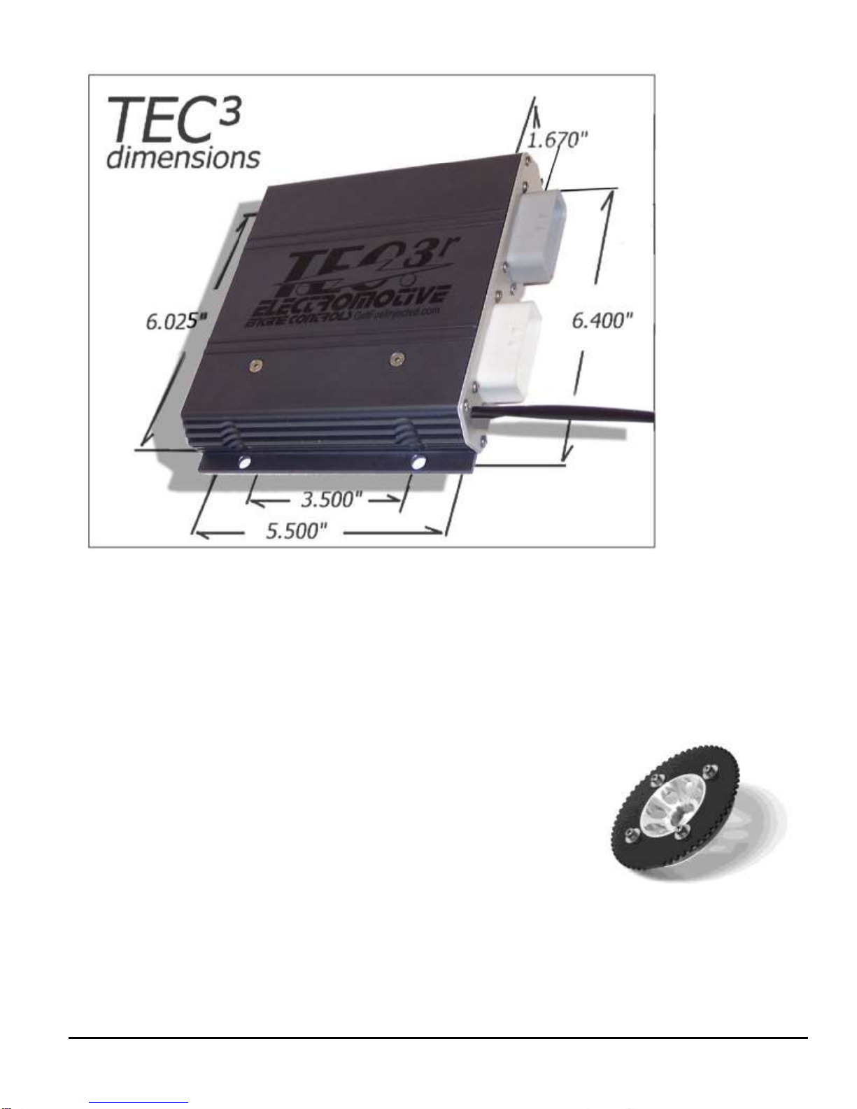
Tec3r Manual Version 1.11 - Page 13 - ©2017 Electromotive, Inc.
Tec3-r ECU Dimensions (bolt pattern is 3.5” x 6.025”)
A.4. Trigger Wheel and Sensor Installation
The foundation of the Tec3-r ultra-high resolution ignition is the
60(-2) tooth trigger wheel. The trigger wheel is designed to give
uncompromising timing accuracy at the highest engine acceleration rates. As
such, Electromotive does not support other triggering systems, particularly
those of the “flying magnet” variety. These systems can lead to vastly
inaccurate spark timing, and can contribute to engine damage. For most
applications, the 60(-2) tooth trigger wheel is mounted on the crankshaft
damper or pulley. Some applications may warrant the use of a camshaft- or
distributor-mounted trigger wheel. With this setup, a 120(-4) tooth trigger wheel is necessary, since the
camshaft turns at half the speed of the crank.

Tec3r Manual Version 1.11 - Page 14 - ©2017 Electromotive, Inc.
A.4.a. Crankshaft Trigger Installation for 60(-2) Tooth Wheel
For a crankshaft-mounted trigger wheel setup, an appropriate place must be found to mount the wheel
and trigger. Typically, the easiest place to mount a trigger wheel is on the harmonic damper or pulley. If it
is mounted on a damper, it should be mounted on the inner hub rather than the outer dampening ring. The
damper/pulley should be keyed to the crankshaft so that it cannot spin on the crankshaft, as this would cause
an ignition timing error. When using a damper that has bolt-on pulleys, the trigger wheel can usually be
mounted between the pulleys and the damper. However, the accessory pulleys will need to be shimmed out
by 1/8” (the thickness of the trigger wheel). A variety of application-specific trigger wheels are available.
See Appendix II for a listing of applications. Universal trigger wheels are also available in a variety of
sizes, and are listed in Appendix II as well. Electromotive can custom-make trigger wheels in nearly any
configuration for a one-time tooling fee.
To choose the proper size trigger wheel, find the diameter of the pulley or damper on which the
wheel is to be mounted. The trigger wheel diameter should be about ½” larger than this diameter. It should
also be noted that the trigger wheel should be at least ¼” from any moving magnetic pieces, such as bolts or
other fasteners, to avoid interference and false triggering. It is important that the trigger wheel be perfectly
concentric with the crankshaft centerline. To achieve concentricity, a shallow cut can be machined in the
front or rear face of the damper to create a centering ledge, and a hole can be created in the trigger wheel to
match the ledge diameter. The trigger wheel can then be drilled to bolt it to the damper.
See Table A.4.1 below to determine the tolerances that must be maintained when mounting the
trigger wheel. These tolerances may require the use of a lathe to true the trigger wheel with the crankshaft
centerline, which can be accomplished by putting the entire damper/trigger wheel assembly on the lathe.
Note that the maximum out-of-round is the distance between the lowest and highest teeth and the crank
sensor. That is, if a feeler gauge is used between the sensor and the wheel to measure the out-of-round, the
reading between the lowest and highest teeth should not exceed the guidelines in the table.
Trigger
Wheel
Size
Air Gap
Maximum
Out-of-
Round
2.5"
0.025" max
0.002"
3.5"
0.035" max
0.003"
5"
0.050" max
0.005"
6"
0.060" max
0.006"
7.25"
0.070” max
0.007"
8.25"
0.080” max
0.008"
A.4.b. Magnetic Crank Sensor Installation
When installing the magnetic sensor, an appropriate bracket must be made to aim the sensor at the
trigger wheel. A good starting point for a magnetic sensor bracket is Electromotive part number 210-72003,
which is our universal sensor bracket (See Figure A.4.1). If
this part is not used as a starting point, a custom bracket can
easily be made. The most important things to remember
when fabricating a bracket are that it should be bolted
directly to the engine block, away from rotating steel or
magnetic pieces, and should be nonferrous (not attracted to
magnets). This will keep the sensor and trigger wheel
vibrating together so the gap between the two always stays the
same. Variations in sensor gap may cause erratic timing or
false triggering of the ignition. (This is the reason for not
mounting the trigger wheel to the outer ring of a harmonic
damper.) As such, any custom magnetic sensor bracket should be
Fig A.4.1 : Universal Crank Sensor Bracket
Table A.4.1:
Crank Trigger Specifications
Tec3r Manual Version 1.11 - Page 15 - ©2017 Electromotive, Inc.
very rigid. The sensor can be secured with either a set screw or a clamping arrangement, as long as the 1/2”
sensor is utilized (part number 250-72218). If the smaller 3/8” sensor is utilized, a clamping arrangement
should be employed rather than a setscrew, as the setscrews may crush the sensor. See Table A.4.2 for the
appropriate magnetic sensor/trigger wheel combinations.
Once a magnetic sensor and trigger wheel are installed, they must be aligned such that the Tec3-r
computer knows where to locate Top Dead Center of the #1 cylinder (referred to as TDC #1). Correct
alignment necessitates that the center of the sensor must be aligned with the trailing edge of the 11th
tooth after the two missing teeth when the engine is at TDC #1 (see the drawing at the end of this
section). Aligning the magnetic sensor with anything other than the 11th tooth will cause an ignition timing
retard or advance, depending on the direction of the misalignment. Each tooth represents six degrees, so if
the sensor is aligned with the trailing edge of the 12th tooth, the timing will be advanced by six degrees.
Conversely, if the sensor is aligned with the trailing edge of the 10th tooth, the timing will be retarded by six
degrees. In the event that the sensor is not aligned correctly, the Wintec software can be made to compensate
by manipulating the Tooth Offset Parameter, as outlined in Section A.4.g of this manual.
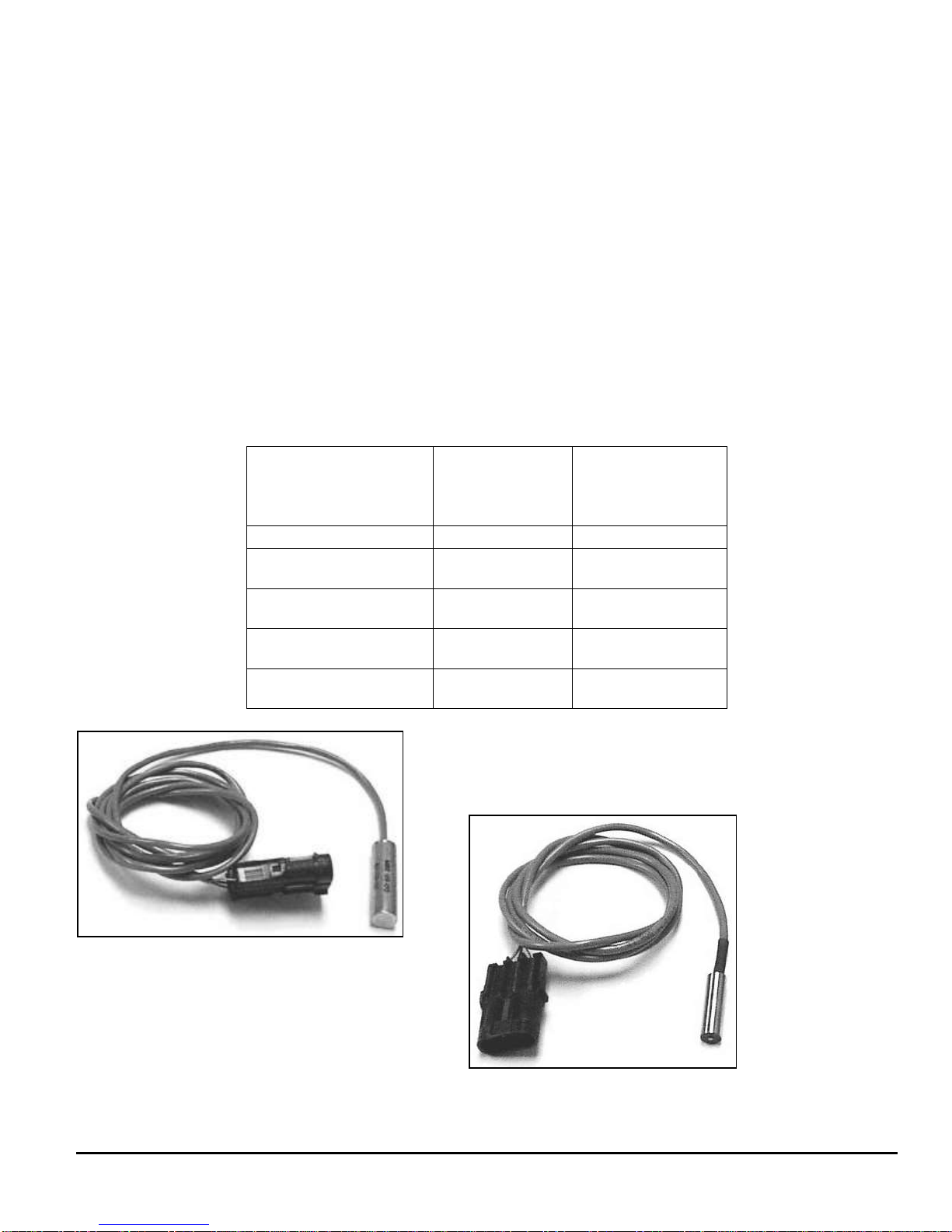
Table A.4.2: Magnetic crank sensor selection. Note: use a clamping arrangement for securing 3/8”
sensors, rather than a setscrew. The ½” sensors can be secured with any clamping method.
Fig A.4.2: Electromotive ½” (12.7mm)
crank sensor
Fig A.4.3: Electromotive 3/8”
(9.53mm) crank sensor
3/8” Diameter
Chisel Point
Sensor
PN: 250-72212
1/2” Diameter
Flat Tip
Sensor
PN: 255-72218
All 120 (-4) Tooth
X
2-3/8” & 2-1/2”
60 (-2) Tooth
X
3-1/2” 60 (-2) Tooth
(below 6000rpm)
X
X
3-1/2” 60 (-2) Tooth
(Above 6000rpm)
X
X
Greater than 3-1/2”
60 (-2) Tooth wheels
X
X

Tec3r Manual Version 1.11 - Page 16 - ©2017 Electromotive, Inc.
A.4.c. Wiring the Magnetic Sensor
The crank sensor has three wires. The red wire is the signal from the sensor, the black wire is the
signal ground, and the bare wire is the shield. The harness has provisions for both a crank and a cam sensor.
The crank sensor cable must be used for all 60 (-2) or 120 (-4) tooth trigger wheel inputs. The cam
sensor cable should only be used for the “sync” pulse from the cam-mounted trigger wheel on sequential
applications. If you are unsure which cable is for the crank sensor, measure the resistance between pin G9
on the Tec3-r harness and the red wire coming out of both the crank and cam cables. The wire that reads
zero resistance to pin G9 is the crank sensor wire. See Figure A.4.4 for details. Consult the end of this
section for details on sequential applications.
Figure A.4.4: Wiring layout for crank and cam sensors. Note that the Cam Sensor is only used on full
sequential applications. It is NOT used on applications using the 120(-4) tooth cam trigger wheel with no
crank trigger.
A.4.d. Verifying Trigger Wheel Timing
The most important step in the trigger wheel installation process is to check the ignition advance with
a timing light. A timing indicator (pointer) should be attached to the engine block, and it should point at a
line on the crankshaft pulley or trigger wheel when the engine is at TDC #1. When running the engine,
verify that the timing value read by the timing light corresponds to the timing value in the software’s engine
monitor screen.
Use of a good-quality inductive timing light is recommended. DO NOT use a timing light that goes
between the spark plug and spark plug wire with a clamp probe. Dial-Back inductive timing lights can be
used, but will need to be dialed to DOUBLE the actual desired timing value due to the waste-spark firing of
the DFU coils. They are fooled into thinking that the timing is twice as advanced as it actually is.

Tec3r Manual Version 1.11 - Page 17 - ©2017 Electromotive, Inc.

Tec3r Manual Version 1.11 - Page 18 - ©2017 Electromotive, Inc.
A.4.e. Camshaft- & Distributor-Mounted Trigger Setups
While crankshaft mounted triggers are preferred, it is sometimes easier to install a camshaft- or
distributor-mounted trigger wheel. For these cases in which the trigger wheel is spinning at half the engine
speed, a 120(-4) tooth trigger wheel is necessary. This wheel has two sets of two missing teeth, spaced 180
degrees apart. As such, the input to the Tec3-r is identical to that of the crank-mounted 60(-2) tooth trigger
wheel. Electromotive offers 120 (-4) tooth wheels in 3.25” and 2.75” diameters.
It is often easy to use an old distributor rotor to serve as the mount for a 120(-4) tooth trigger wheel.
A simple nonferrous bracket would need to be fabricated to hold the sensor. The 3/8” chisel point sensor
(PN: 250-72212) must be used on 120(-4) trigger wheels. As such, the bracket for the sensor should use a
clamping arrangement rather than a setscrew to hold the magnetic sensor. Just like the crank-mounted
trigger, the distributor/cam-mounted triggers require the sensor to be aligned with the trailing edge of
the 11th tooth after the two missing teeth when the engine is at TDC #1. The same tolerances that apply
to the crankshaft-mounted trigger wheels (Table A.4.1) apply to the camshaft-mounted trigger wheels as
well.
A Note on Engines with High-Overlap Camshafts:
If your engine is equipped with a camshaft that has early intake valve openings or very long duration,
you may experience backfiring through the throttle during starting. This is caused by the intake valves
beginning to open on the exhaust stroke. Since the spark plugs fire on both the compression and the exhaust
strokes, the spark on the exhaust stroke may cause unburned fuel in the intake manifold to ignite, resulting in
a backfire.
To remedy this situation, advance the “mechanical” timing by manipulating the DFU “A” Trigger
Wheel TDC Parameter. If your crank sensor is aligned with the 11th tooth of the trigger wheel at TDC #1,
setting the Tooth Offset to a number LOWER than 11 will add mechanical advance. If the number “10” was
set for the Tooth Offset, the mechanical timing would be ADVANCED by 6 degrees (6 degrees per tooth).
This would require that you subtract 6 degrees from the values in your ignition advance table in Wintec to
obtain your desired advance value. That is, the timing table will have to read 30 degrees in order for the
engine to operate at 36 degrees advance. See Section A.4.g. for more details.
A.4.f. Full Sequential Applications –Cam Synchronization
When full sequential fuel operation is desired, a once-per-engine-cycle synchronization, or “sync,”
pulse must be received by the ECU. Typically, the sync pulse is generated by the installation of a 1-notch
(or 1-tooth) trigger wheel onto the camshaft. A standard Electromotive magnetic (inductive) sensor can then
be used to obtain the reading from this trigger wheel. A Hall effect sensor could also be used as a triggering
method instead of a magnetic sensor setup. With either method, the tooth must pass by the magnetic sensor
between 180oand 6obefore TDC Compression (not exhaust) of the number one cylinder. See Figure A.4.7
for installation details.
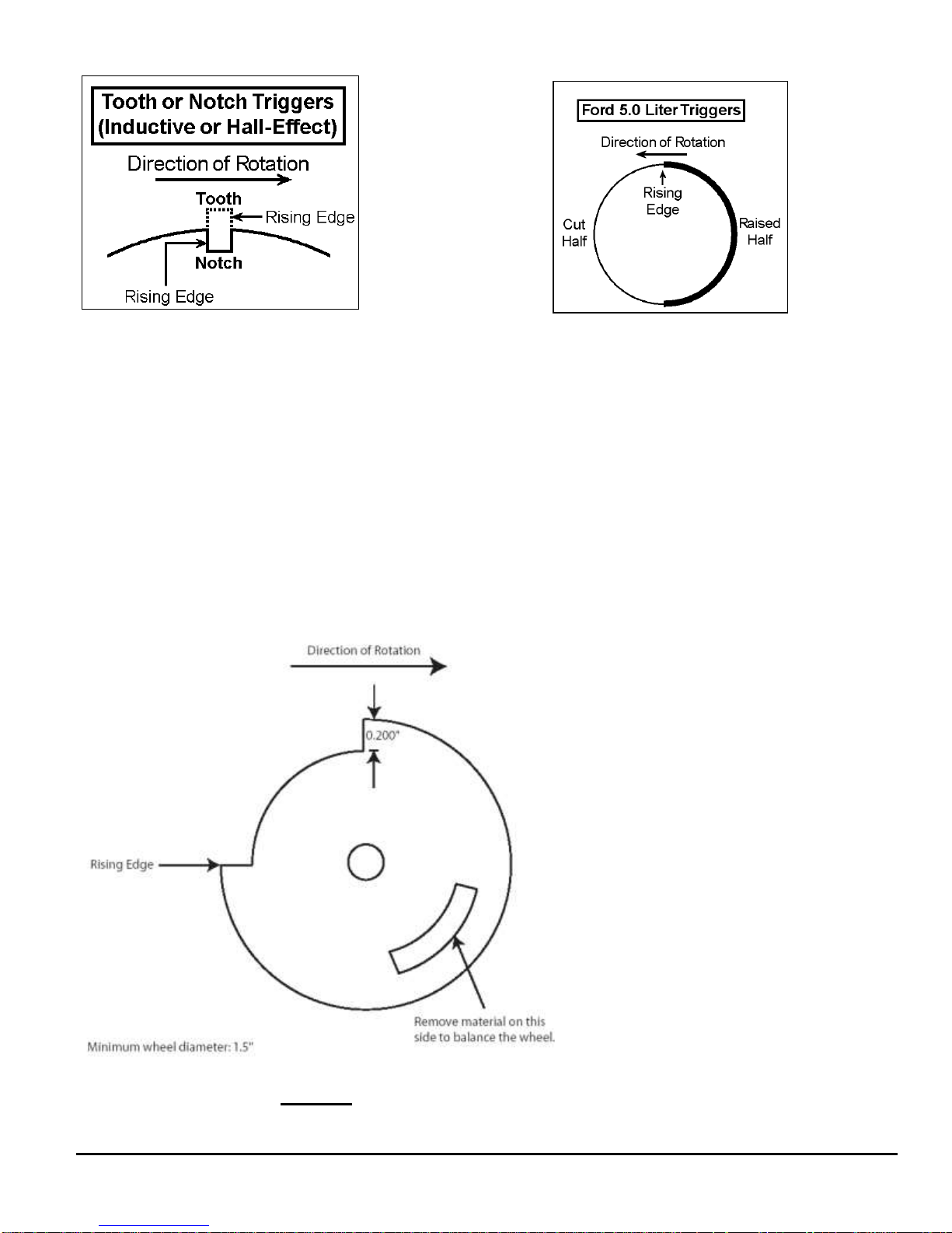
The Tec3-r will only trigger off a rising edge during the synchronization period (between 180o
and 6oBTDC compression). A rising edge occurs when the metal on the cam trigger wheel becomes closer
to the sensor over a very short period of time. See Figures A.4 6 and 7 for representative examples and
different cam trigger wheel designs, and their rising edge location.
Tec3r Manual Version 1.11 - Page 19 - ©2017 Electromotive, Inc.
Most types of sensors are compatible with the TEC’s sync pulse requirement. This would include
most Hall effect, flying magnet, and reluctor sensors. As long as the sensor outputs a rising voltage to the
Tec3-r between 180oand 6obefore TDC compression for the number one cylinder, it should work
perfectly.
Terminal G10 on the ECU is used for cam sync inputs (as shown in Figure A.4 4). If using a Hall
effect or other sensor type that is powered by +5Volts, be sure that the output signal from the sensor is going
into terminal G10. If using a magnetic sensor with a custom steel trigger wheel, we recommend using our
magnetic sensors. The red wire from the sensor should go to terminal G10. Keep in mind that when
adapting an OEM cam trigger setup to a Tec3-r, the wheel may need to be rotated to place the rising edge in
the appropriate degree window for the Tec3-r.
A.4.g. TDC Tooth Setup Software Adjustment Parameters
Figure A.4 8:
Proper cam trigger
installation. This
cam trigger occurs
approx. 90oBTDC
Compression on the
#1 cylinder (as
measured at the
crank). Note the 87
degree (as
measured on the
cam wheel)
“window” in which
the rising edge must
occur.
Figure A.4 6:
Tooth/Notch
Triggers
Figure
A.4 7:
Ford “Half-
Moon”
Trigger

Tec3r Manual Version 1.11 - Page 20 - ©2017 Electromotive, Inc.
So, you took a lot of time to install your trigger wheel, and now you realize that you didn’t get the
trailing edge of the 11th tooth to align with the center of the magnetic sensor with the engine at TDC #1.
What to do?
The Wintec software features a TDC setup parameter that allows users to manipulate the TDC point
for the trigger wheel. There are two adjustable parameters:
Change DFU “A” Trigger Wheel TDC
Change DFU “B” Trigger Wheel TDC
For all but the odd-fire applications, the adjustment is only present for the DFU “A” TDC. The
default setting for DFU “A” TDC is 11, signifying TDC alignments with the 11th tooth. If you are aligned
with the 13th tooth at TDC, change this number to 13. Several late-model Bosch-equipped applications use
our 60 (-2) tooth trigger wheel, but come from the factory with a different TDC tooth alignment. Typically,
these setups are referenced to the 14th tooth for TDC, but you MUST confirm this on your application, since
Bosch used a few different offsets through the years.
Odd-Fire applications have the ability to move the TDC reference for the second DFU (using the
parameter “DFU “B” Trigger Wheel TDC”). This allows the user to define the odd-fire ignition split that is
present on the engine. Refer to Section C.5 to determine the proper settings for this value.
Some applications may require more “mechanical timing” to compensate for large, high-overlap
cams. Assuming the crank sensor is aligned with the 11th tooth at TDC, this can be done by entering a value
for the “Change DFU “A” Trigger Wheel TDC” that is LESS than 11. Each tooth less than 11 represents 6
degrees of advance that is added to the Ignition Advance Table.
Some applications may require less “mechanical timing” (some rotary users may wish to do this).
Assuming the crank sensor is aligned with the 11th tooth at TDC, this can be done by entering a value for the
“Change DFU “A” Trigger Wheel TDC” that is MORE than 11. Each tooth more that 11 represents 6
degrees of retard that is subtracted from the Ignition Advance Table.
If an odd-fire engine has the trigger wheel installed incorrectly, and the DFU “A” TDC parameter is
changed to compensate for the error, the “DFU “B” Trigger Wheel TDC” parameter needs to be manipulated
in the same amount. As an example, if the TDC for DFU “A” is at 11 and is moved to 10, the TDC for DFU
“B” would need to be moved from 16 to 15.
The following pages outline the various situations that can be addressed through the TDC software
parameters.
Situation A
Problem: Incorrect trigger wheel alignment results in undesired mechanical timing.
Solution: With the engine at TDC #1, find the trigger wheel tooth that is aligned with the crank sensor.
Enter the number of this tooth into the TDC Tooth Alignment Parameter. The timing will be shifted to make
the Ignition Advance Table accurate.
Method: The software will automatically RETARD the timing when a number GREATER THAN 11 is
entered into the TDC Tooth Alignment Parameter. The timing will be automatically ADVANCED when a
number LESS THAN 11 is entered.
Situation B
Problem: The engine needs more mechanical advance, and the crank sensor is aligned with the 11th tooth.
Solution: Enter in the number “10” to the TDC Tooth Alignment Parameter. The timing values will be
automatically ADVANCED by 6 degrees. The Ignition Advance Table values will now be incorrect (the
displayed values will be 6 degrees lower than the actual advance).
Situation C
Problem: The engine needs less mechanical advance, and the crank sensor is aligned with the 11th tooth.
Table of contents
Other Electro motive Automobile Accessories manuals


Popular Automobile Accessories manuals by other brands

Continental Refrigerator
Continental Refrigerator NTG7 MID LFT2 User instruction manual

Nokia
Nokia Cark-112 installation guide

Akyga
Akyga AK-CH-09 user manual

bp
bp pulse home user guide

Menabo
Menabo DELTA DL FIX 201FP Fitting instructions

Edscha Trailer Systems
Edscha Trailer Systems CS-LitePlus quick guide

APS Auto Parts Specialist
APS Auto Parts Specialist IB06EJB8 installation instructions

PNEUMATIC
PNEUMATIC KU-RE-LO00-02 Installation instruction

Smittybilt
Smittybilt 2783 owner's manual

Thule
Thule 1417 instructions

BORLA
BORLA 60087 installation instructions

Havis-Shields
Havis-Shields 2004-2008 Ford Econoline Van C-VS-1800-ECO Install instructions

 user manual")


