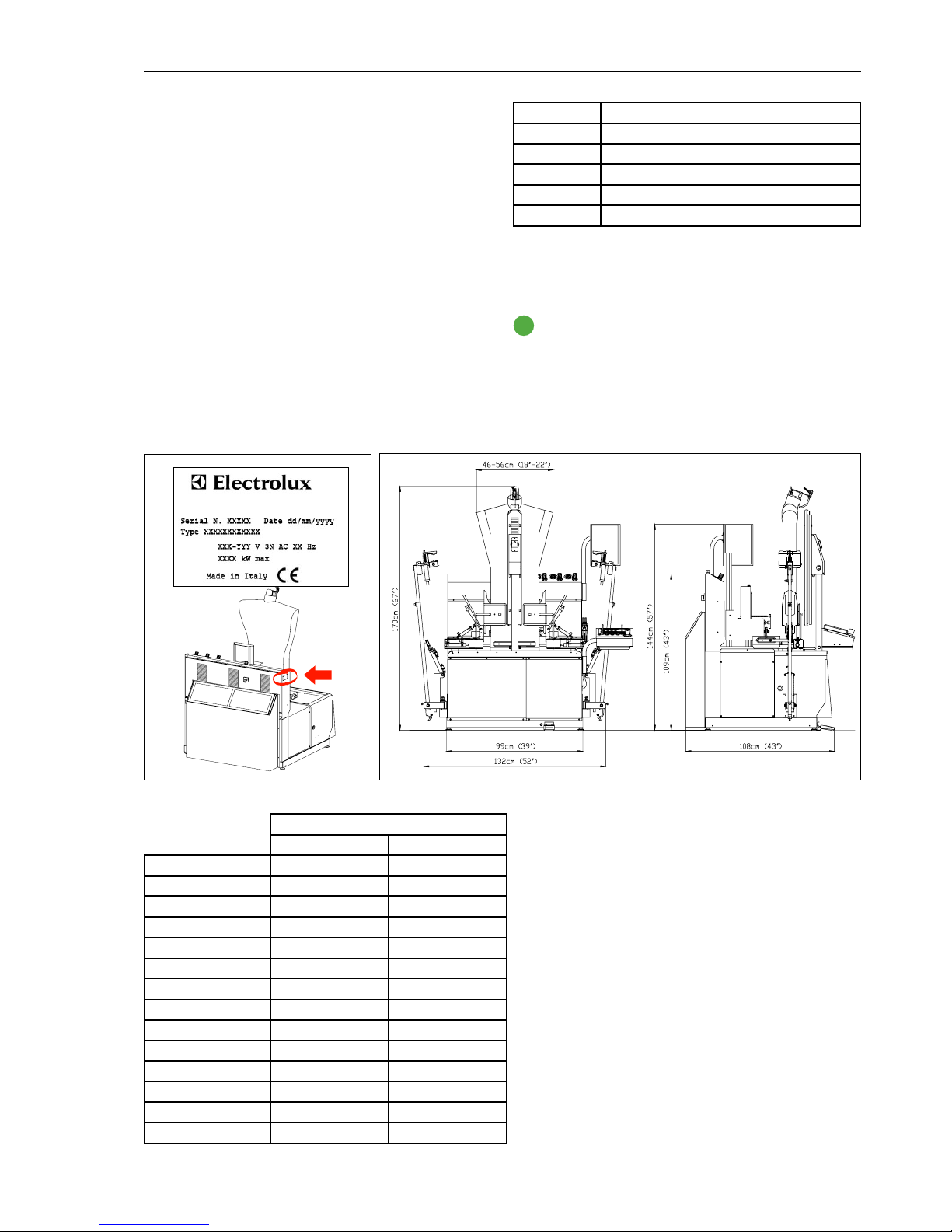
8
4. Use
The form finisher here described is made for pressing wet cleaned
shirts.
This shirt finisher is designed for:
• Garment manufacturing industries;
• Large and small Industrial dry cleaners;
• Garment finishing industries.
The shirt finisher must be utilized by qualified personnel, who have
been specifically trained on this type of machinery.
4.1. Safety precautions
During operation the unit is under electrical tension:
• Do not operate machinery with partially exposed or frayed
wiring.
• Never permit water to come into contact with machine:
danger of electrical shock, short-circuiting and damage
to machine may result.
• Do not open the machine cabinet.
The unit has various parts that reach extremely high tem-
peratures:
• Do not leave the machine unattended while it is on;
• Keep all flammable substances away from machine, to
avoid risk of fire;
• Do not open machine body
• Do not replace cover and padding while machine is hot
(wait at least 2 hours after turning it off). Always check
the temperature of the form before proceeding to substi-
tute covers.
The unit generates hot steam vapors - Stay clear of steam
reflex jet.
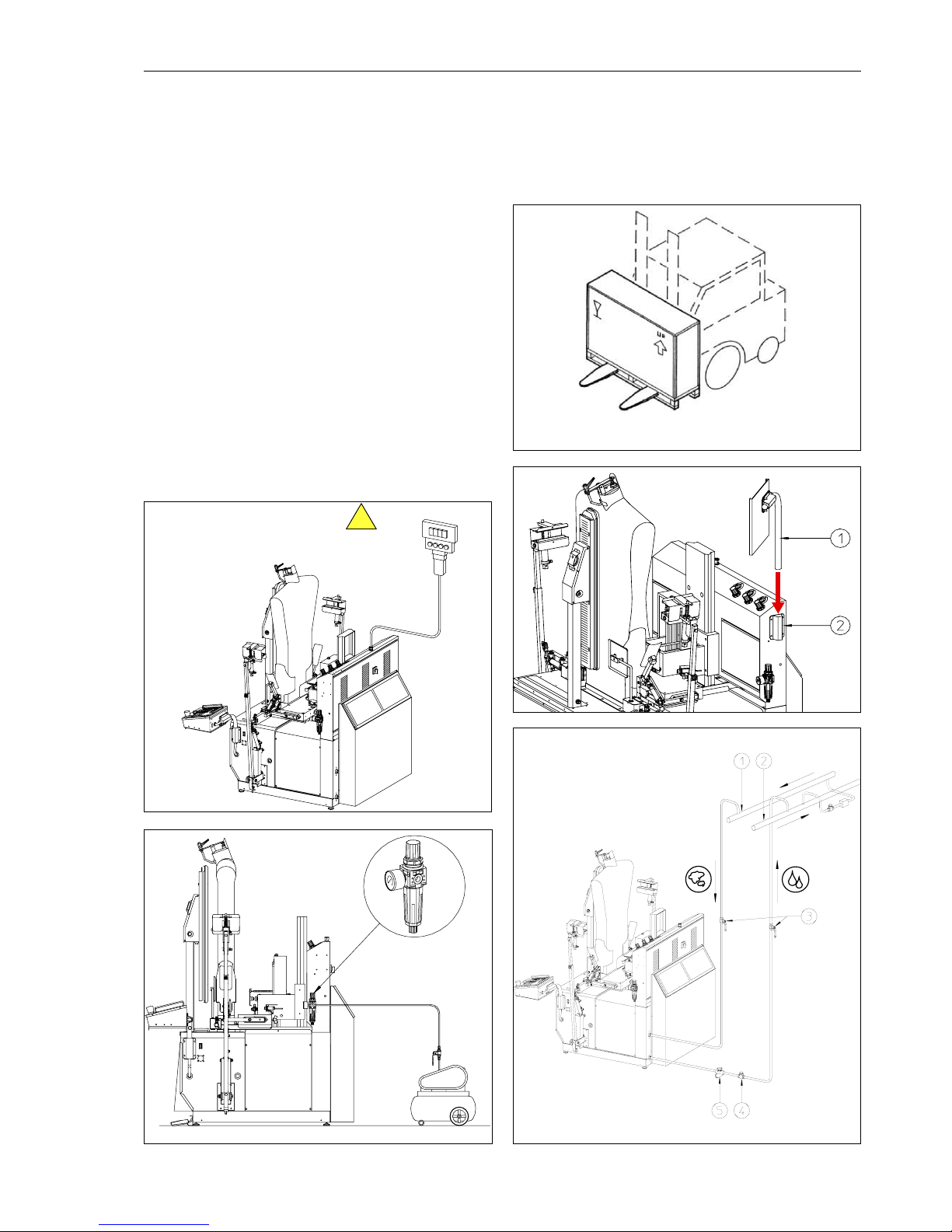
4.2. Before starting
1. Open the steam and condensate return valves
2. Open the air delivery valve
3. Turn on main power switch (2 - Figure 4.3)
4.3. Operation
Refer to figures 4.2 and 4.3
WARNING - BURN HAZARD - The front clamp may
reach very high temperature. Do not touch it while
the machine is on.
4.3.1. Position of the operator
During dressing, cycle start and undressing the operator stands in
front of the machine.
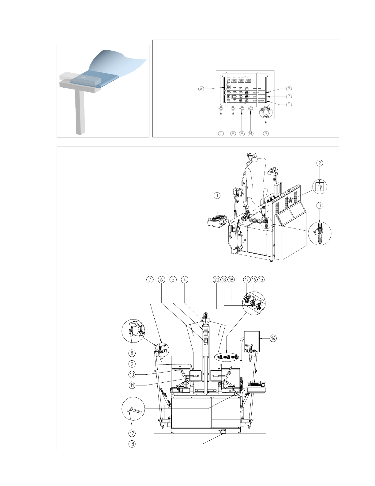
4.3.2. Settings
1. Select program number with buttons (A) on the control panel
2. Select blowing power shifting the lever (12)
Check the general pressure in the machine, displayed by
the gauge located on the air filter (3). The gauge should
display 6 bar. Use the knob on top of the air filter (3) to adjust
the general pressure.
4.3.3. Pressing
Press the Start pedal (13) to move one step forward in the dressing
sequence. If you make a mistake, press the BACK CYCLE button on
the control panel to “undo” the last step.
1. Place the shirt on the form and adjust shoulder width with the
buttons (E) and (F) on the control panel;
2. Step on the start pedal (13) to close the collar clamp;
3. Step on the start pedal to find the height;
4. Grab the sides of the shirt and tense the back part of the shirt
against the form while stepping on the start pedal: the rear
clamp closes. During this operation, look in the mirror (14) to
check that there are no wrinkles in the area where the rear
clamp closes;
5. Grab the two front edges of the shirt and position them parallel
along the front part of the form;
6. The suction keeps the two parts in position. Smooth the front
edges to make sure there are no wrinkles;
7. Step on the start pedal to close the front clamp and expand
sides;
8. Insert a cuff in the cuff clamp and push button (8) to close
the clamp. If you want to re-open the clamp, push the button
again. To avoid marks insert the cuff unbuttoned and as shown
in figure 4.1;
9. Insert the other cuff in to the other clamp and push the button
to close. When the second cuff clamp closes, the machine au-
tomatically starts the cycle;
10. Adjust sleeve arms height so that there are no wrinkles in the
armpit area (see paragraph 4.6.1);
11. At the end of the cycle the clamps are automatically released.
4.3.4. Use of the iron (optional)
If your shirt finisher is equipped with an iron for touch-ups (the iron
is an optional feature), the iron can be used at any time during the
pressing cycle to perfect finishing.
If you want to keep full control of the quality of the garment proceed
as follows:
1. Insert the MANUAL END function located in the “mode” section
of the control panel (C). At the end of the pressing cycle the
clamps are not released and the garment is kept in place for
visual inspection;
2. If the garment needs touch-ups: press AIR in the “manual con-
trols” section of the control panel (D) to start the blowing and
inflate the garment;
3. Use the iron to finish the garment or add manual steam by
pressing the button STEAM in section (D) of the control panel;
4. Press END CYCLE in the “manual controls” section of the con-
trol panel (D) to release the clamps.
- The iron must be used and rested on a stable surface;
- when placing the iron on its stand, ensure that the surface on
which the stand is placed is stable;
- the iron is not to be used if it has been dropped, if there are
visible signs of damage or if it is leaking.
4.4. In case of emergency
In case of emergency at any time during the cycle, push
the red mushroom (G). The machine will stop imme-
diately any operation and the clamps will be released.
To reset the machine, turn the mushroom clockwise.
4.5. Upon terminating work
1. Turn off the main power switch.
2. Close steam and condensate return valves.
3. Close air delivery valve.
4.6. Fine adjustments
Refer to Figure 4.3 if not otherwise specified
The machine has several fine adjustment, to match any kind of ap-
plication.
Front clamp temperature: Rotate the temperature dial to adjust the
temperature of the front clamp. The temperature needed for
most fabrics is between 160 and 180 °C. This temperature must
be selected according to type of fabric and degree of extrac-
tion.
Rear clamp and side clamps pressure adjustment: pull knob (18) and
rotate clockwise to increase the pressure on rear clamp and
side clamps. The pressure value is indicated by gauge (17).
When finished, push knob in to lock in position. The recom-
mended value is 3 bar.
Strength of additional sleeve tension: When additional sleeve ten-
sion is activated (see parameter H04 in the next para-
graph) the strength of the tension can be adjusted.
Use
(> Continued on page 10)
F4VA1-ed3605
F4VA1