Electronics International Inc CGR-30P User manual


Important Notice
***** MUST READ *****
Page 1 of 4
If you think it is not important to read this manual, you’re wrong! This manual
contains important operating information that may affect the safety of you, your
aircraft and passengers.
Read the Warranty / AgreementRead the Warranty / Agreement
Read the Warranty / AgreementRead the Warranty / Agreement
Read the Warranty / Agreement. There is information in the Warranty/Agreement that may alter your
decision to install this product. If you do not accept the terms of the Warranty / Agreement, doIf you do not accept the terms of the Warranty / Agreement, do
If you do not accept the terms of the Warranty / Agreement, doIf you do not accept the terms of the Warranty / Agreement, do
If you do not accept the terms of the Warranty / Agreement, do
not install this productnot install this product
not install this productnot install this product
not install this product. This product may be returned for a refund. Contact Electronics International
inc. for details.
By installing this product, the aircraft owner/pilot and installer agree to hold Electronics International Inc.
harmless and in no way responsible for monetary compensation, including punitive damages for any
incident, harm and/or damage associated with this product. If you do not agree to the above, DO NOTDO NOT
DO NOTDO NOT
DO NOT
INSTALL THIS PRODUCT.INSTALL THIS PRODUCT.
INSTALL THIS PRODUCT.INSTALL THIS PRODUCT.
INSTALL THIS PRODUCT. This product may be returned for a refund. Contact Electronics Interna-
tional inc. for details.
The pilot mustmust
mustmust
must
understand the operation and limitations of this product before flying the aircraft. Do not
allow anyone to operate the aircraft that does not know how to properly interpret and operate this product.
Keep the Operating Instructions in the aircraft at all times. If you do not thoroughly understand the
operation of this product, contact a knowledgeable flight instructor for training.
The ability for this product to respond to an engine or aircraft system anomaly is directly related to how
that anomaly affects the reading of the function(s) being monitored (i.e.; if an engine fire does not affect
the EGT or CHT, the EGT and CHT readings will not change).
This instrument only displays the parameters for the function(s) being monitored. The pilot is responsible
for interpreting the data and determining if an engine or aircraft system anomaly exists. When using this
instrument, the pilot’s diagnostic ability is limited to his/her interpretation of the displayed data and the
their observation skills. To improve these skills the pilot should seek training from a flight instructor.
If after reading this manual you do not have the knowledge to interpret the displayed data to operate the
aircraft safely or to detect engine and/or aircraft system problems, contact a knowledgeable instructor for
training prior to flying the aircraft with this instrument.
If you detect a problem using this instrument, it is your responsibility to take appropriate action to ensure
the safety of the flight. Practice simulating problems to build your skills and to improve your understand
of the relationships between problems and their affects on the displayed data. To ensure you are taking
appropriate action, contact a knowledgeable flight instructor for training. Inappropriate action can lead to
aircraft and/or engine damage, personal injury or death.
This manual does not make any recommendations as to specific operating parameters or controlling
methods. Check the airframe and/or engine manufacturer’s recommendations to properly operate the
aircraft systems and engine. It is the pilot’s responsibility to operate the engine and aircraft safely.

Important Notice
***** MUST READ *****
Page 2 of 4
It is possible for any instrument to fail thereby displaying inaccurate high, low or jumpy readings.
Therefore, you mustmust
mustmust
must be able to recognize an instrument failure and you mustmust
mustmust
must be proficient in operating
your aircraft safely in spite of an instrument failure. If you do not have this knowledge, contact the FAA
or a knowledgeable flight instructor for training prior to flying the aircraft with this instrument.
Electronics International Inc. is not liable or responsible for a pilot’s action or any situation that results in
personal injury, property damage, missed commitments, lack of use of an aircraft or any expenses
incurred due to: product failure, inaccuracy in displayed data or text files, display or display format
issues, software bugs or problems, upgrade or customization issues, misinterpretation of the display,
warning and/or limit settings, calibration problems, installation issues (leaks, mis-wiring, obstructions,
damage to aircraft or components, incorrect installation of any parts, wrong parts, parts that don’t fit,
etc.) or any other issues related to the installation or operation of this product. All of the above are
solely the pilot’s and/or installer’s responsibility. The pilot mustmust
mustmust
must
understand the operation of this prod-
uct before flying the aircraft. The pilot must not allow anyone to operate the aircraft that does not know
the operation of this product. The pilot must keep the instrument Operating Instructions in the aircraft at
all times.
Set a unique password to protect all of the calibration and setup data in the CGR-30P. If setup or calibra-
tion data is inadvertently or improperly changed, you could get inaccurate readings that may lead to
improper operation of the aircraft or engine. This could result in engine damage and/or an emergency
situation.
Before flying the aircraft verify that the instrument markings displayed on the CGR are accurate with
your POH for every function displayed on the CGR.
The CGR must be calibrated to the aircraft fuel system and the CGR's accuracy must be verified before
flying the aircraft.
Fuel Level Accuracy Limitations:Fuel Level Accuracy Limitations:
Fuel Level Accuracy Limitations:Fuel Level Accuracy Limitations:
Fuel Level Accuracy Limitations:
The accuracy limitations of the CGR are listed below. It is the pilot/owner’s obligation to makeIt is the pilot/owner’s obligation to make
It is the pilot/owner’s obligation to makeIt is the pilot/owner’s obligation to make
It is the pilot/owner’s obligation to make
anyone flying the aircraft aware of these limitations.anyone flying the aircraft aware of these limitations.
anyone flying the aircraft aware of these limitations.anyone flying the aircraft aware of these limitations.
anyone flying the aircraft aware of these limitations.
1. Angle of Attack -1. Angle of Attack -
1. Angle of Attack -1. Angle of Attack -
1. Angle of Attack - The CGR must be calibrated with the aircraft in a cruise angle of attack. If the
aircraft is in an angle of attack other than cruise, the CGR may display inaccurate fuel levels (depending
on the mounting location and type of sensor used). If your aircraft does not sit at a cruise angle of attack
when on the ground, it may not display accurate fuel levels. Test your aircraft at different anglesTest your aircraft at different angles
Test your aircraft at different anglesTest your aircraft at different angles
Test your aircraft at different angles
of attack to determine how the CGR fuel level readings are affected.of attack to determine how the CGR fuel level readings are affected.
of attack to determine how the CGR fuel level readings are affected.of attack to determine how the CGR fuel level readings are affected.
of attack to determine how the CGR fuel level readings are affected.
2. Full Fuel Readings -Full Fuel Readings -
Full Fuel Readings -Full Fuel Readings -
Full Fuel Readings - As a tank is filled the fuel sensor may be unable to detect the fuel entering

Important Notice
***** MUST READ *****
Page 3 of 4
the upper corners of the fuel tank. If this is the case with your sensor, the CGR may display fuel levels
lower than the actual fuel in the tanks when the tanks are full. When the fuel level drops to a point
where the fuel sensor starts to detect a change, the displayed fuel level should be accurate. Check theCheck the
Check theCheck the
Check the
accuracy of your system by comparing the displayed fuel levels on the CGR to the fuelaccuracy of your system by comparing the displayed fuel levels on the CGR to the fuel
accuracy of your system by comparing the displayed fuel levels on the CGR to the fuelaccuracy of your system by comparing the displayed fuel levels on the CGR to the fuel
accuracy of your system by comparing the displayed fuel levels on the CGR to the fuel
levels listed in the flight manual at each fill up.levels listed in the flight manual at each fill up.
levels listed in the flight manual at each fill up.levels listed in the flight manual at each fill up.
levels listed in the flight manual at each fill up.
3. Low Fuel Readings -3. Low Fuel Readings -
3. Low Fuel Readings -3. Low Fuel Readings -
3. Low Fuel Readings - Do not rely on the CGR to determine the fuel level in the tankDo not rely on the CGR to determine the fuel level in the tank
Do not rely on the CGR to determine the fuel level in the tankDo not rely on the CGR to determine the fuel level in the tank
Do not rely on the CGR to determine the fuel level in the tank
for an indicated tank level below 1/8for an indicated tank level below 1/8
for an indicated tank level below 1/8for an indicated tank level below 1/8
for an indicated tank level below 1/8. You should always fly the aircraft in such a manner as to
at least maintain the FAA minimum fuel requirements in the aircraft at all times. Depending on theDepending on the
Depending on theDepending on the
Depending on the
mounting location and type of fuel sensor used, the CGR may not be able to accuratelymounting location and type of fuel sensor used, the CGR may not be able to accurately
mounting location and type of fuel sensor used, the CGR may not be able to accuratelymounting location and type of fuel sensor used, the CGR may not be able to accurately
mounting location and type of fuel sensor used, the CGR may not be able to accurately
measure the last few gallons of fuel in the tanks.measure the last few gallons of fuel in the tanks.
measure the last few gallons of fuel in the tanks.measure the last few gallons of fuel in the tanks.
measure the last few gallons of fuel in the tanks.
4. Improper Calibration -4. Improper Calibration -
4. Improper Calibration -4. Improper Calibration -
4. Improper Calibration - If the CGR has not been properly calibrated, it will not display accurate
fuel levels in the tanks. It is important to verify the accuracy of the CGR. Always cross check yourAlways cross check your
Always cross check yourAlways cross check your
Always cross check your
measured fuel levels in the tanks with the readings on the CGR before each flight.measured fuel levels in the tanks with the readings on the CGR before each flight.
measured fuel levels in the tanks with the readings on the CGR before each flight.measured fuel levels in the tanks with the readings on the CGR before each flight.
measured fuel levels in the tanks with the readings on the CGR before each flight.
5. Poor Connections -5. Poor Connections -
5. Poor Connections -5. Poor Connections -
5. Poor Connections - Poor connections between the wires leading from the EDC to the fuel
sensors can become intermittent with age. An intermittent connection most likely will show up as
wandering or inaccurate readings on the CGR. Always cross check your measured fuel levelsAlways cross check your measured fuel levels
Always cross check your measured fuel levelsAlways cross check your measured fuel levels
Always cross check your measured fuel levels
in the tanks with the readings on the CGR before each flight.in the tanks with the readings on the CGR before each flight.
in the tanks with the readings on the CGR before each flight.in the tanks with the readings on the CGR before each flight.
in the tanks with the readings on the CGR before each flight.
6. Defective Fuel Level Sensors -6. Defective Fuel Level Sensors -
6. Defective Fuel Level Sensors -6. Defective Fuel Level Sensors -
6. Defective Fuel Level Sensors - Fuel sensors can become intermittent or change resistance
with age. It is not uncommon to find intermittent problems even in new resistive sensors. An intermit-
tent problem with a fuel sensor most likely will show up as wandering or inaccurate readings on the
CGR. Always cross check the measured fuel levels in the tanks with the readings on theAlways cross check the measured fuel levels in the tanks with the readings on the
Always cross check the measured fuel levels in the tanks with the readings on theAlways cross check the measured fuel levels in the tanks with the readings on the
Always cross check the measured fuel levels in the tanks with the readings on the
CGR at each fill up.CGR at each fill up.
CGR at each fill up.CGR at each fill up.
CGR at each fill up.

Important Notice
***** MUST READ *****
Page 4 of 4
Important Fuel Level Considerations:Important Fuel Level Considerations:
Important Fuel Level Considerations:Important Fuel Level Considerations:
Important Fuel Level Considerations:
DO NOT RELY SOLELY ON THE FUEL LEVEL DISPLAYED ON THE CGR TODO NOT RELY SOLELY ON THE FUEL LEVEL DISPLAYED ON THE CGR TO
DO NOT RELY SOLELY ON THE FUEL LEVEL DISPLAYED ON THE CGR TODO NOT RELY SOLELY ON THE FUEL LEVEL DISPLAYED ON THE CGR TO
DO NOT RELY SOLELY ON THE FUEL LEVEL DISPLAYED ON THE CGR TO
DETERMINE THE FUEL LEVELS IN THE AIRCRAFT.DETERMINE THE FUEL LEVELS IN THE AIRCRAFT.
DETERMINE THE FUEL LEVELS IN THE AIRCRAFT.DETERMINE THE FUEL LEVELS IN THE AIRCRAFT.
DETERMINE THE FUEL LEVELS IN THE AIRCRAFT. The use of the CGR does notThe use of the CGR does not
The use of the CGR does notThe use of the CGR does not
The use of the CGR does not
eliminate or reduce the necessity for the pilot to use good flight planning, preflight andeliminate or reduce the necessity for the pilot to use good flight planning, preflight and
eliminate or reduce the necessity for the pilot to use good flight planning, preflight andeliminate or reduce the necessity for the pilot to use good flight planning, preflight and
eliminate or reduce the necessity for the pilot to use good flight planning, preflight and
in-flight techniques for managing fuel.in-flight techniques for managing fuel.
in-flight techniques for managing fuel.in-flight techniques for managing fuel.
in-flight techniques for managing fuel. It is important the pilot adopt the practices listed below.
If you are not familiar with these techniques, contact the FAA to acquire proper training.
1.1.
1.1.
1. A copy of these Operating Instructions must be in the aircraft at all times.A copy of these Operating Instructions must be in the aircraft at all times.
A copy of these Operating Instructions must be in the aircraft at all times.A copy of these Operating Instructions must be in the aircraft at all times.
A copy of these Operating Instructions must be in the aircraft at all times.
2. Flight Planning -2. Flight Planning -
2. Flight Planning -2. Flight Planning -
2. Flight Planning - Always calculate the fuel requirement for each leg of a flight, including any
alternate plans for bad weather or other problems. Keep this information available in the aircraft
during the flight. Keep a chart of the published fuel flows for various flight/engine conditions in the
aircraft. Keep a chart of the measured fuel flows for various flights in the aircraft. Measured fuel
flows can be considerably different from published figures.
3. Preflight - Do not rely on the CGR to determine the fuel level in the fuel tanks. The3. Preflight - Do not rely on the CGR to determine the fuel level in the fuel tanks. The
3. Preflight - Do not rely on the CGR to determine the fuel level in the fuel tanks. The3. Preflight - Do not rely on the CGR to determine the fuel level in the fuel tanks. The
3. Preflight - Do not rely on the CGR to determine the fuel level in the fuel tanks. The
pilot must visually check/measure the fuel levels in the tanks before every takeoff.pilot must visually check/measure the fuel levels in the tanks before every takeoff.
pilot must visually check/measure the fuel levels in the tanks before every takeoff.pilot must visually check/measure the fuel levels in the tanks before every takeoff.
pilot must visually check/measure the fuel levels in the tanks before every takeoff. Cross
check the measured fuel levels with the displayed levels on the CGR. Also, cross check these levels
with the fuel requirements for the flight listed in your flight plan.
4. In Flight -4. In Flight -
4. In Flight -4. In Flight -
4. In Flight - Make the CGR part of your normal instrument scan. Crosscheck the fuel levelsCrosscheck the fuel levels
Crosscheck the fuel levelsCrosscheck the fuel levels
Crosscheck the fuel levels
displayed on the CGR with your flight plan at each leg of the flight or every 30 minutesdisplayed on the CGR with your flight plan at each leg of the flight or every 30 minutes
displayed on the CGR with your flight plan at each leg of the flight or every 30 minutesdisplayed on the CGR with your flight plan at each leg of the flight or every 30 minutes
displayed on the CGR with your flight plan at each leg of the flight or every 30 minutes
(if a leg is longer than 30 minutes). Calculate the fuel flows from the CGR displayed fuel levels and
compare them with your charts of measured and published fuel flows for the aircraft. If there is a
discrepancy, land the aircraft at the nearest airport and verify the fuel levels. Discrepancies should be
taken seriously.
5. New Pilot or Owner of the Aircraft -5. New Pilot or Owner of the Aircraft -
5. New Pilot or Owner of the Aircraft -5. New Pilot or Owner of the Aircraft -
5. New Pilot or Owner of the Aircraft - If there is a new pilot or new owner of theIf there is a new pilot or new owner of the
If there is a new pilot or new owner of theIf there is a new pilot or new owner of the
If there is a new pilot or new owner of the
aircraft, it is the previous aircraft pilot/owner’s responsibility to insure the new pilot/aircraft, it is the previous aircraft pilot/owner’s responsibility to insure the new pilot/
aircraft, it is the previous aircraft pilot/owner’s responsibility to insure the new pilot/aircraft, it is the previous aircraft pilot/owner’s responsibility to insure the new pilot/
aircraft, it is the previous aircraft pilot/owner’s responsibility to insure the new pilot/
owner has read this manual and is aware of any accuracy limitations and other importantowner has read this manual and is aware of any accuracy limitations and other important
owner has read this manual and is aware of any accuracy limitations and other importantowner has read this manual and is aware of any accuracy limitations and other important
owner has read this manual and is aware of any accuracy limitations and other important
considerations. All limitations and operating characteristics learned from operating theconsiderations. All limitations and operating characteristics learned from operating the
considerations. All limitations and operating characteristics learned from operating theconsiderations. All limitations and operating characteristics learned from operating the
considerations. All limitations and operating characteristics learned from operating the
CGR must be passed on to the new pilot/owner.CGR must be passed on to the new pilot/owner.
CGR must be passed on to the new pilot/owner.CGR must be passed on to the new pilot/owner.
CGR must be passed on to the new pilot/owner.

Contents
(Page 1 of 2)
Warranty/Agreement----------------------------------------------------------------------------------------- 1
1.0 Introduction: ---------------------------------------------------------------------------------- 3
1.1 Features ------------------------------------------------------------------------------- 5
1.2 Overview of the CGR Screens: -------------------------------------------------------- 5
1.3 System Hardware: --------------------------------------------------------------------- 6
1.4 SELECT Knob and Button Operation: ------------------------------------------------- 7
1.5 Display Dimming: ---------------------------------------------------------------------- 7
1.6 Cleaning the Screen: ------------------------------------------------------------------- 7
2.0 Main Engine Screen: -------------------------------------------------------------------------- 9
2.1 Power-up Add Fuel Message: --------------------------------------------------------- 11
2.2 Main Screen Layout: ------------------------------------------------------------------- 11
2.3 RPM and Maniflod Pressure: ---------------------------------------------------------- 12
2.4 Horizontal Strip Gauges: --------------------------------------------------------------- 12
2.5 Bar Graph Analyzer: ------------------------------------------------------------------- 12
2.6 Main Screen Annunciators: ------------------------------------------------------------ 15
2.7 External Master Caution and Warning Light: ------------------------------------------- 15
2.8 Voice Alarm Control Panel (OEM Only): ---------------------------------------------- 15
3.0 Secondary Screen: --------------------------------------------------------------------------- 17
3.1 RPM and Mainifold pressure Gauges: ------------------------------------------------- 18
3.2 Three Annunciators: ------------------------------------------------------------------- 18
3.3 Six Horizontal Strip and/or Digital Gauges: --------------------------------------------- 18
3.4 EGT/CHT Digital Gauges: ------------------------------------------------------------- 18
4.0 Fuel Qtys Screens: --------------------------------------------------------------------------- 20
4.1 Fuel Quantity: ------------------------------------------------------------------------- 22
4.2 Selecting a Tank: ---------------------------------------------------------------------- 22
4.3 Adding Fuel: -------------------------------------------------------------------------- 22
4.4 K-Factor Adjustments: ---------------------------------------------------------------- 23
5.0 Fuel Data Screen: ---------------------------------------------------------------------------- 24
5.1 Total Fuel Cylinder: ------------------------------------------------------------------- 26
5.2 Fuel: FLOW ------------------------------------------------------------------------- 26
5.3 Fuel: EST DIST ---------------------------------------------------------------------- 26
5.4 Fuel: EST QTYS --------------------------------------------------------------------- 26
5.5 Fuel: EST TIME ---------------------------------------------------------------------- 27
5.6 Fuel: EST AT DEST ------------------------------------------------------------------ 27
5.7 Fuel: EST USED --------------------------------------------------------------------- 27

6.0 User Setup Screens: -------------------------------------------------------------------------- 28
6.1 Fuel K-Factor Screen: ----------------------------------------------------------------- 30
6.2 Clock and Hour Meters Screen: ------------------------------------------------------- 31
6.3 EGT/CHT Bar Graph Setup Screen: --------------------------------------------------- 31
6.4 USB and Data Recording Screen: ------------------------------------------------------ 32
6.5 Fuel Alarm and Unit Info Screen: ------------------------------------------------------- 32
6.6 System Config Screens Menu: ---------------------------------------------------------- 33
7.0 System Configuration Screens ---------------------------------------------------------------- 34
7.1 USB Config and SW Prg Manager Screen: -------------------------------------------- 36
7.2 Change Passwords Screen: ------------------------------------------------------------ 36
7.3 Aircraft ID Screen: --------------------------------------------------------------------- 37
7.4 Hour Meters and Flight Timers Screen: ------------------------------------------------ 37
7.5 Serial Port and EDC Setup Screen: ---------------------------------------------------- 37
7.6 Engine and EGT/CHT Bar Graph Setup Screen: --------------------------------------- 38
7.7 Fuel Tank Setup Screen: --------------------------------------------------------------- 38
7.8 Display and Voice Controls Screen: ---------------------------------------------------- 40
7.9 CGR Input/Output Tests Screen: ------------------------------------------------------- 40
7.10 Horsepower Calibration Screen: ------------------------------------------------------ 41
7.11 Function Configuration Screen: ------------------------------------------------------- 41
7.11.1 Probe Calibration Screen: ------------------------------------------------- 44
7.11.2 Function Mapping Screen (Fuel Tank Calibration): ------------------------- 46
Appendix ------------------------------------------------------------------------------------------ 48
A1.0 Specifications/Features:
A2.0 RecordedFlightData Format
Contents
(Page 2 of 2)

1
Warranty / Agreement
You must read the entire Installation and Operating Instructions. If you do not agree to andYou must read the entire Installation and Operating Instructions. If you do not agree to and
You must read the entire Installation and Operating Instructions. If you do not agree to andYou must read the entire Installation and Operating Instructions. If you do not agree to and
You must read the entire Installation and Operating Instructions. If you do not agree to and
accept the terms of this warranty/agreement and the responsibilities set forth in these manuals,accept the terms of this warranty/agreement and the responsibilities set forth in these manuals,
accept the terms of this warranty/agreement and the responsibilities set forth in these manuals,accept the terms of this warranty/agreement and the responsibilities set forth in these manuals,
accept the terms of this warranty/agreement and the responsibilities set forth in these manuals,
DO NOT install this product. Contact E.I. for a refund.DO NOT install this product. Contact E.I. for a refund.
DO NOT install this product. Contact E.I. for a refund.DO NOT install this product. Contact E.I. for a refund.
DO NOT install this product. Contact E.I. for a refund.
Electronics International Inc. (EI) warrants this instrument and system components to be free from defects in
materials and workmanship for a period of one year from the purchase date. EI will repair or replace any item
under the terms of this Warranty provided the item is returned to the factory prepaid.
Electronics International Inc. is not liable or responsible for a pilot’s action or any situation that results in
personal injury, property damage, missed commitments, lack of use of an aircraft or any expenses incurred due
to: product failure, inaccuracy in displayed data or text files, display or display format issues, software bugs or
problems, upgrade or customization issues, misinterpretation of the display, warning and/or limit settings,
calibration problems, installation issues (leaks, mis-wiring, obstructions, damage to aircraft or components,
incorrect installation of any parts, wrong parts, parts that don’t fit, etc.) or any other issues related to the instal-
lation or operation of this product. All of the above are solely the pilot’s and/or installer’s responsibility. The
pilot mustmust
mustmust
must
understand the operation of this product before flying the aircraft. The pilot will not allow anyone
to operate the aircraft that does not know the operation of this product. The pilot will keep the instrument
Operating Instructions in the aircraft at all times.
By installing this product, the aircraft owner/pilot and installer agree to hold Electronics International Inc.
harmless and in no way responsible for monetary compensation, including punitive damages for any incident,
harm and/or damage associated with this product (including but not limited to the ones listed above). If you do
not agree to the above, DO NOT INSTALL THIS PRODUCT.DO NOT INSTALL THIS PRODUCT.
DO NOT INSTALL THIS PRODUCT.DO NOT INSTALL THIS PRODUCT.
DO NOT INSTALL THIS PRODUCT.
This Warranty shall not apply to any product that has been repaired or altered by any person other than Elec-
tronics International Inc., or that has been subjected to misuse, accident, incorrect wiring, negligence, improper
or unprofessional assembly or improper installation by any person. This warranty does not cover anyThis warranty does not cover any
This warranty does not cover anyThis warranty does not cover any
This warranty does not cover any
reimbursement for any person’s time for installation, removal, assembly or repair.reimbursement for any person’s time for installation, removal, assembly or repair.
reimbursement for any person’s time for installation, removal, assembly or repair.reimbursement for any person’s time for installation, removal, assembly or repair.
reimbursement for any person’s time for installation, removal, assembly or repair. Electronics
International retains the right to determine the reason or cause for warranty repair and if the product will be
covered.
Personal injury or property damage due to misinterpretation or lack of understanding of this product is solely
the pilot’s responsibility. The pilot mustmust
mustmust
must
understand all aspects of the operation of this product before flying
the aircraft. If he/she does not, he/she agrees to seek training from a knowledgeable instructor. Do not allow
anyone to operate the aircraft that does not know the operation of this product. Keep the Operating Instruc-
tions in the aircraft at all times.
This warranty does not extend to any machine, vehicle, boat, aircraft or any other device to which the Electron-
ics International Inc. product may be connected, attached, interconnected or used in conjunction with in any
way.
The obligation assumed by Electronics International Inc. under this warranty is limited to repair, replacement or
refund of the product, at the sole discretion of Electronics International Inc.
Electronics International Inc. is not liable for expenses incurred by the customer or installer due to factory
updates, modifications, improvements, changes, or any other alterations to the product that may affect the
form, fit, function or operation of the product.
More On Next PageMore On Next Page
More On Next PageMore On Next Page
More On Next Page

2
Electronics International is not responsible for shipping charges or damages incurred under this Warranty.
No representative is authorized to assume any other liability for Electronics International Inc. in connection
with the sale of Electronics International Inc. products.
This Warranty is made only to the original user. THIS WARRANTY IS IN LIEU OF ALL OTHERTHIS WARRANTY IS IN LIEU OF ALL OTHER
THIS WARRANTY IS IN LIEU OF ALL OTHERTHIS WARRANTY IS IN LIEU OF ALL OTHER
THIS WARRANTY IS IN LIEU OF ALL OTHER
WARRANTIES OR OBLIGATIONS: EXPRESS OR IMPLIED. MANUFACTURER EXPRESSLYWARRANTIES OR OBLIGATIONS: EXPRESS OR IMPLIED. MANUFACTURER EXPRESSLY
WARRANTIES OR OBLIGATIONS: EXPRESS OR IMPLIED. MANUFACTURER EXPRESSLYWARRANTIES OR OBLIGATIONS: EXPRESS OR IMPLIED. MANUFACTURER EXPRESSLY
WARRANTIES OR OBLIGATIONS: EXPRESS OR IMPLIED. MANUFACTURER EXPRESSLY
DISCLAIMS ALL IMPLIED WARRANTIES OF MERCHANTABILITY OR FITNESS FOR ADISCLAIMS ALL IMPLIED WARRANTIES OF MERCHANTABILITY OR FITNESS FOR A
DISCLAIMS ALL IMPLIED WARRANTIES OF MERCHANTABILITY OR FITNESS FOR ADISCLAIMS ALL IMPLIED WARRANTIES OF MERCHANTABILITY OR FITNESS FOR A
DISCLAIMS ALL IMPLIED WARRANTIES OF MERCHANTABILITY OR FITNESS FOR A
PARTICULAR PURPOSE. PURCHASER AGREES THAT IN NO EVENT SHALL MANUFAC-PARTICULAR PURPOSE. PURCHASER AGREES THAT IN NO EVENT SHALL MANUFAC-
PARTICULAR PURPOSE. PURCHASER AGREES THAT IN NO EVENT SHALL MANUFAC-PARTICULAR PURPOSE. PURCHASER AGREES THAT IN NO EVENT SHALL MANUFAC-
PARTICULAR PURPOSE. PURCHASER AGREES THAT IN NO EVENT SHALL MANUFAC-
TURER BE LIABLE FOR SPECIAL, INCIDENTAL OR CONSEQUENTIAL DAMAGES, IN-TURER BE LIABLE FOR SPECIAL, INCIDENTAL OR CONSEQUENTIAL DAMAGES, IN-
TURER BE LIABLE FOR SPECIAL, INCIDENTAL OR CONSEQUENTIAL DAMAGES, IN-TURER BE LIABLE FOR SPECIAL, INCIDENTAL OR CONSEQUENTIAL DAMAGES, IN-
TURER BE LIABLE FOR SPECIAL, INCIDENTAL OR CONSEQUENTIAL DAMAGES, IN-
CLUDING LOST PROFITS OR LOSS OF USE OR OTHER ECONOMIC LOSS. EXCEPT ASCLUDING LOST PROFITS OR LOSS OF USE OR OTHER ECONOMIC LOSS. EXCEPT AS
CLUDING LOST PROFITS OR LOSS OF USE OR OTHER ECONOMIC LOSS. EXCEPT ASCLUDING LOST PROFITS OR LOSS OF USE OR OTHER ECONOMIC LOSS. EXCEPT AS
CLUDING LOST PROFITS OR LOSS OF USE OR OTHER ECONOMIC LOSS. EXCEPT AS
EXPRESSLY PROVIDED HEREIN, MANUFACTURER DISCLAIMS ALL OTHER LIABILITYEXPRESSLY PROVIDED HEREIN, MANUFACTURER DISCLAIMS ALL OTHER LIABILITY
EXPRESSLY PROVIDED HEREIN, MANUFACTURER DISCLAIMS ALL OTHER LIABILITYEXPRESSLY PROVIDED HEREIN, MANUFACTURER DISCLAIMS ALL OTHER LIABILITY
EXPRESSLY PROVIDED HEREIN, MANUFACTURER DISCLAIMS ALL OTHER LIABILITY
TO PURCHASER OR ANY OTHER PERSON IN CONNECTION WITH THE USE OR PERFOR-TO PURCHASER OR ANY OTHER PERSON IN CONNECTION WITH THE USE OR PERFOR-
TO PURCHASER OR ANY OTHER PERSON IN CONNECTION WITH THE USE OR PERFOR-TO PURCHASER OR ANY OTHER PERSON IN CONNECTION WITH THE USE OR PERFOR-
TO PURCHASER OR ANY OTHER PERSON IN CONNECTION WITH THE USE OR PERFOR-
MANCE OF MANUFACTURER’S PRODUCTS, INCLUDING SPECIFICALLY LIABILITY INMANCE OF MANUFACTURER’S PRODUCTS, INCLUDING SPECIFICALLY LIABILITY IN
MANCE OF MANUFACTURER’S PRODUCTS, INCLUDING SPECIFICALLY LIABILITY INMANCE OF MANUFACTURER’S PRODUCTS, INCLUDING SPECIFICALLY LIABILITY IN
MANCE OF MANUFACTURER’S PRODUCTS, INCLUDING SPECIFICALLY LIABILITY IN
TORT.TORT.
TORT.TORT.
TORT.

1.01.0
1.01.0
1.0
IntroductionIntroduction
IntroductionIntroduction
Introduction
1.1 Features:
1.2 Overview of the CGR Screens:
1.3 System Hardware:
1.4 SELECT Knob and Button Operation:
1.5 Display Dimming:
1.6 Cleaning the Screen:
3

1.1 Features:
The CGR-30P is a state-of-the-art GlassPanel Engine Monitorthat
providesmanyoftheengineandsysteminstrumentsfoundinanaircraft
panel. Eachoftheinstrumentsdisplayed ontheCGR’sMainEngine
Screenprovidesfeaturesnotfoundinmostmultifunctionaldisplaysor
traditionalgauges.
Aircraftpanelsequippedwithindividualinstrumentsrequireapilotto
scanandinterpret amultitude ofgauges spread acrossan entirepanel.
Byprovidingasinglelocationforviewingtheengineandmanyaircraft
systeminstruments,the CGRreduces a pilot’s workload andthe chance
ofmissingaproblem. Additionally,theCGRprovides bothanalogand
digitaldisplayswithdigitsthatblinkandchangecolorswhenyellowor
redoperating rangesare reached. Also,an externalCaution and
Warning Lightcanbe placedin front ofthe pilot. All ofthese featuresare
designedtoalertthe pilotthemoment any monitoredfunctionenters a redoryellow operatingrange.
1.2 Overview of the CGR Screens:
MainScreen(seesection 2.0): The Main Screen displays most of the
engineandaircraftinstruments monitored bytheCGR. Thisis thescreen
theCGRdisplays afterpower-up and isthe screenthepilot willview for
mostoftheflight.
SecondaryScreen(seesection 3.0): The Secondary screen is
intendedtodisplay functionsthat donotneed tobe displayed
continuously. Although,onefunctionwithared(warning)and/or yellow
(caution)can be placed on theSecondary screen.
Ifa primaryfunction on theSecondary screenreaches ared oryellow
operatingrange,an annunciatorlocated between thetwo arcgauges
locatedat the topof theMain Screenwillblink. In thisway thepilot is
alertedofa potentialproblem andshould view theSecondary screenfor
furtherinformation.
FuelQtys Screens (see section4.0): Depending on the way the
CGR-30Pissetup, theFuelQtys Screen willdisplaythe estimatedfuel
levelsforthedifferentaircraftfueltanksoritwilldisplaythetotalfuel
onboard. Thesetup dependson howthe aircraft handles fuel tothe
engine(i.e.;iftheenginereturnsfuel to asinglefueltankorifyou can
selectbothtanks, then onlytotalfuel willbedisplayed). Also, theFuel
QtysScreen allows the pilot toadd fuel toa tank.
5
Main Screen
SecondaryScreen
Fuel Qtys Screen
FuelData Screen (see section5.0): The Fuel Data Screen provides
sixsets ofdata basedon Fuel Flow and GPSinformation. This data
includesRange,DistancetoDestination,Rangeafterreachingyour
Destination,FuelRemaining,FueltoDestination,FuelReserve,Timeto
Empty,TimetoDestination,TimeReserve,FuelUsedfor theFlight,Fuel
Usedsince fuelwasAdded,Economy(MPGs) andTotalFuelonboard.
Muchof this datadepends on anRS232 connection toyour GPS.
User Setup Screens (see section 6.0): The User Setup Screen Menu
providesa listof setupscreens forsetting theK-Factor, settingclocks,
viewingtheTachandEngineHours,setting thedisplayrangeforthe bar
graph,downloadingrecorded data andsettingup theRecurringFuel
Alarm.
SystemConfigScreens(seesection7.0): The System Config
ScreensallowsElectronicsInternational tosetupthe CGR-30P foralmostany function foranyaircraft. These
screens are password protected.
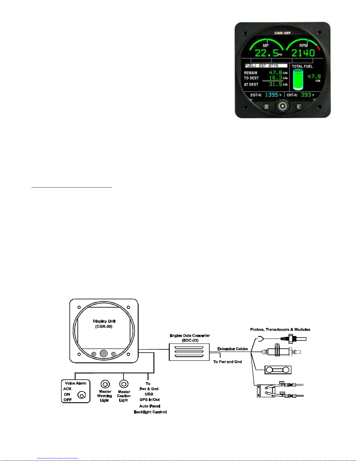
1.3 System Hardware:
TheCGR-30Phardwareconsists ofthefollowingthree groupsofcomponents:
A. Probes,TransducersandExtensionCables–These components are used to measure pressures,
temperatures,fuelflow,volts,amps,fuellevelsandmany other engineandaircraftsystemfunctions. The
analogsignals produced bythe transducersand probesare routedthrough the ExtensionCables to
variousEDCinputs.
B. EDC(Engine DataConverter)– The EDC-33Pconverts the analogsignals from theprobes and
transducersto adigital format. This datais transmittedvia aone-wire +5VSerial cableto theCGR
Display.
6
Fuel Data Screen

C. CGRDisplay – The CGR receives, processes and displays the Serial EDCdata on its TFT color
display. Inaddition, theCGR receivesGPSdata, interfaceswith theVoiceWarningControl Paneland
monitorstheexternal backlightcontrol line. Also,theCGR transmitsfueldata totheGPS andcontrols
theexternalCautionandWarningLights.
TheCGR reducesthe number ofpanel-mounted instrumentsfrom around12 toonly 1. TheEDC canreduce the
totalnumberof wiresrouted totheaircraft instrumentpanel by 50or more.
1.4 SELECT Knob and Button Operation:
SELECTKnob: The SELECT knob can be rotated or pressed.
Dependingonthe screen andfieldbeing viewed,rotatingthe knob can
moveanarrow,select adigit, orchange a digit’svalue. Pressing the
SELECTknobwillchoosethehighlighteditem.
SCREENSButton: Pressing theSCREENS button sequencesthe
CGRthrough the fourdisplay screens(Main, Secondary,Fuel Qtyand FuelData).
EXITButton: Pressingthe EXITbuttonwill exityouout ofa specific operation. Repeatedpresses willexityou
outof thecurrent screenand return you to theMain Screen.
1.5 Display Dimming:
TheCGRprovides anexternaldimming controllineto dimthedisplay. TheCGRcan beset to dimon any input
voltageswing. Dimmingcalibrationissetupinthe Display &VoiceControlsscreenfound in section7ofthis
manual.
1.6 Cleaning the Screen:
TheCGR incorporates aflat panelfull colorTFTdisplay,whichshould beprotected fromscratches. TheTFT
displayshouldbecleanedusingonlyisopropylalcoholandasoftcleaningcloth. Individuallywrappedlens-cleaning
tissue(used toclean glassesor plasticlenses) worksbest.
7

9
2.02.0
2.02.0
2.0
Main Engine ScreenMain Engine Screen
Main Engine ScreenMain Engine Screen
Main Engine Screen
2.1 Power-up Add Fuel Message:
2.2 Main Screen Layout:
2.3 RPM and Manifold Pressure:
2.4 Horizontal Strip Gauges:
2.5 Bar Graph Analyzer:
2.5.1 “EGT/CHT”Operating Mode:
2.5.2 “Normalized”Operating Mode:
2.5.3 “Lean - ROP” Operating Mode:
2.5.4 “Lean- LOP” Operating Mode:
2.5.5“EGT”Digital Operating Mode:
2.5.6“CHT”Digital Operation Mode:
2.6 Main Screen Annunciators:
2.7 External Master Caution and Warning Lights:
2.8 Voice Alarm Control Panel (OEM Only):

11
TheMainEngine Screendisplaystheaircraftsystemandengineinstrumentsyouwillviewmostfrequentlyduringa
flight. Thereisimportantinformationpublishedin theImportant Noticesection(foundinthefrontof this
manual)that mustbe readbeforeoperating thisinstrument. Pleaseread the ImportantNotice section atthis
time.
2.1 Power-up Add Fuel Message:
TheCGR requiresapproximately 15seconds to power-up. Youmay
wanttoswitch on theMasterSwitch whenfirstentering theaircraftto
insurethe CGRis powered up when youare readyto startthe engine.
An“ImportantSafetyInfo”and“AddFuelMessage”willappearwhen
theCGRisfullypoweredup. Thepurposeofthismessageistoremind
youtoreadtheimportantinformationandtoupdatethefuelcomputerif
youhaveaddedfueltotheaircraft. TheCGRcandisplaytheestimated
fuelon-boardtheaircraftcalculatedfromthefuelflow. Thisallowsyou
tocrosscheckthefuelreadingsonyourfuellevelgaugetoensure
accuracy. The“AddFuelMessage”canbeacknowledgedbypressing
the“Exit”buttonor(ifyouhaveaddedfueltotheaircraft)youcan
changethedisplayedfuelquantitybypressingthe“Select”knob.
2.2 Main Screen Layout:
TheMainScreenislaidoutinthefollowingfourareas:
RPM and Manifold Pressure (see section 2.3): The RPM and
ManifoldPressureinstruments arelocatedat thetop of theMain
screen. Eachof theseinstruments incorporates alarge arcand
digitaldisplay. Otherfunctionsmaybe placed inthislocation.
ThreeHorizontal Strip Gauges (see section 2.4): Aseries of
threeHorizontalStripGauges (withdigitalreadouts)are located on
therightsideof thescreen. Anumberofdifferentfunctionsmaybe
placedinthislocation.
BarGraph (see section 2.5): The Bar Graph is located in the
lowerleftportion ofthe Main screen. TheBar Graphmonitors
bothEGTsand CHTs. TheBar Graph provides both bar graph
anddigitalformatsandincorporatesfeaturesforleaning,detecting
anddiagnosingengine problems. The“SELECTknob controlsthedisplay andoperationof theBarGraph
portionof the screen.
EGT/CHTDigital Gauges(seesection2.5): The two digital displayslocated at the bottomof the Main
screenprovides EGT andCHT data basedon the bargraph operating mode selected.

2.3 RPM and Manifold Pressure:
TheRPMandM.P.instrumentsincorporateadigitalreadoutandan
analogarc. Thecolorofthedigitalreadoutwillreflectthecurrentrange
inwhichthefunctionisoperating(i.e.,iftheRPMisoperatinginthered,
thedigitalreadoutwillbedisplayedinred).
ThedigitaldisplaywillblinkwhentheRPMorM.P.operatinglevel
reachesayelloworredoperatingrange. Tostoptheblinking,pushthe
Exitbutton. Also(ifsoequipped),acknowledgingavoicewarningusing
theexternal“VoiceAlarmControlPanel”willstoptheblinkingofany
digitaldisplay.
TheCGR’sRPMInstrumentprovidesaMagOutfeatureinadditionto
thearcanddigitaldisplay. TheCGRcontinuallymonitorsbothmag
signals. Ifonemagfailsoristurnedoff,anappropriate“MagOut”
warningwillbedisplayedontheappropriatesideoftheRPMdigitaldisplay.
2.4 Horizontal Strip Gauges:
ThethreeHorizontal Strip gaugesprovidethefollowingfeatures:
A. Thecolored operatingranges shownon theHorizontal Stripcan beset upfor any aircraft.
B. EachHorizontalStripGaugefeaturesa pointer (triangle)markingthe current operatinglevel. Also,the
pointerallowsthepilotto interpret rateandtrendinformationand providesfieldofvision.
C. Adigitaldisplayisprovided witheachHorizontalStripGauge.
D. Thedigitsonthedigitaldisplay willblinkwhenafunction’soperating level reachesayelloworred
operatingrange. Tostoptheblinking, pushtheExit button. Also(ifso equipped),acknowledginga voice
warningusingtheexternal“VoiceAlarmControlPanel”willstoptheblinkingofanydigitaldisplay.
2.5 Bar Graph Analyzer:
TheBar GraphAnalyzerhas sixoperating modes: EGT/CHT,Normalized,LeanROP,Lean LOP,EGT and
CHT. TheCGR’s currentmode ofoperation isdisplayed inthe topleft portionof theBar Graph Display. The
SELECTknob maybe usedto changeoperating modes.
2.5.1 “EGT/CHT”Operating Mode: The vertical barsare arranged to show the EGT and CHT for
eachcylinder. Theoperating rangesfor theEGTbars maybe settomatch yourengine’s operating
temperatures(i.e.;if yourfull richlowpower EGTreadingsare around 1100’F, setyour LowEGTRange
for1000’F. Ifyour peak EGTreadings are around 1500’F,set your High EGTRange for 1525’F). The
highand lowEGT ranges may be setin the“EGT/CHT BarGraph Setup”screen (seesection 6).
12
L. Mag
Out

13
IftheEGT foracylinder exceedsthepilot setHighEGT Range,
thebarforthatcylinderwillturn whiteandblink. Thisfeature
providesthe pilot witha warningof a highEGT. TheFAAdoes
notallow exceedanceof user set EGTsto display in redor
yellow.
Ifthe CHTfor a cylinderexceeds theset limit,the barfor that
cylinderwillturnredandblink.
ThecurrentDigitalDisplayModeofoperation is designatedin
thetoprightportionofthe EngineAnalyzer display. The
selectionsareSelect,Diff, ScanandHottest. TheDigital Display
Modecontrolswhatwill bedisplayedinthe digitalsectionatthe
bottomofthe BarGraph display.
SelectMode: The Select Modeallows the pilot to select a cylinder (displayedwith a boxaround the
cylindernumber). TheEGT andCHT for thecylinder selectedareshown inthe bottomportionof the
display.
DiffMode: The DiffModedisplays thedifferencebetween the hottestand coldest EGTand CHT.
Thevalues are displayedat the bottom of the Bar Graph andare designated byEGT-D and CHT-D
Ifadifferentiallimitisexceeded,thedigitalvalueswillbedisplayedinwhite. Thedifferentiallimitsare
setinthe “EGT/CHT BarGraphSetup” screen(seesection 6). Thedifferentiallimitsallow theCGR
todetectdevelopingengine problems beforetheybecomeexpensive repairbills.
ScanMode: The Scan Modeautomatically scansthrough allof the cylinders. Asit scansthrough the
cylinders,theEGT andCHTnumeric valuesaredisplayed inthebottom portionofthe BarGraph
display. Thescan rate can beset in the“EGT/CHTBar GraphSetup” screen.
HottestMode: The HottestMode displays the hottest EGTand CHTin the digital display below
thebars. This is thefavorite modeof operationformost pilots.
2.5.2 “Normalized”OperatingMode: TheNormalized Modeof operationis anengine diagnostictool
thatallowscomparisonof thecurrentEGTsandCHTsto areference(past flight). By normalizingtheEGTs
andCHTsthevertical barsare broughtto thesame level, creatinga referencebaseline.
TheEGTand CHTbarsmay be normalized(leveled)at anytimeby pushingandholding theSelectKnob
forfoursecondsandfollowingthe instructioninthepop-upwindow.
Theoffsetdatato levelthe barsis stored inCGR permanentmemory. TheNormalizedMode allows
changesthat haveoccurred inthe engineto be spotted easily. Thismakesit possible to detect trends over
severalflights,days, weeks,andeven years.

14
2.5.3 “Lean-ROP”OperatingMode: Thisoperating modewas designedto assistthe pilotin leaning
theengineRich-of-Peak EGT. Asyoulean,the EGTbarsfor allcylinderswill rise. When thefirstcylinder
reachespeak EGTa tattletalemarker willappear atthe top ofthat cylinder’s bar. Enrichenthe mixtureand
thefirst cylinderto reachpeak andtheTemp Below Peak(on therich side)will bedisplayed atthe topright
ofthe bargraph displayarea.
2.5.4 “Lean-LOP”OperatingMode:
ImportantNotice: The enginemust beleaned andoperated in
accordancewiththePOH andenginemanufactures
recommendations. Informationin thismanualisforreference
onlyanddoes not makeanyrecommendations.
Thisoperatingmodewasdesignedto assist thepilotinleaning
theengine Lean-of-PeakEGT. Asyoulean, the EGTbars forall
cylinderswillrise. Whenthe firstcylinderreachespeak EGTa
tattletalemarker willappear atthe topof thatcylinder’sbar. As
youcontinuetolean,additionaltattletale markerswillbeplaced
atthe top of theappropriate bar as each cylinder reaches peak
EGT. This givesaquickvisualreference astowhichcylinders
havereached peakEGT andat whattemperature eachcylinder
peaked. Ifa false peak is detected (an EGT dips and then starts
increasingagain),theCGR willresetthe tattletale markerforthat cylinderandonceagain lookforthe true
peak.
Thedata provided inthe topportion ofthe display willshow thefirst cylinder toreach peakEGT andthe
currenttemperaturebelow peakforthat cylinder.
2.5.5 “EGT”DigitalOperatingMode: The EGT DigitalOperating Mode provides a pictorial
representationoftheengineand theEGTsfor each cylinderinadigitalformat. The DigitalDisplayModes
availableare: “Actual”and“Diff.”
Actual: IntheActualModethecurrentEGTsforeachcylinderaredisplayed. Thedataatthe
bottomofthedisplayprovidesthedifference(orspread)betweenthehottestandcoldestEGTand
CHT.
Diff: InthisMode,thecoldestcylinderisindicatedbyareadingof“0.” Eachoftheothercylinders
willdisplaythedifferencebetweenitstemperatureandthetemperatureofthecoldestcylinder. The
dataatthebottomofthedisplayprovidesthetemperatureofthehottestEGTandCHT. Differential
readingsprovidevaluablediagnosticinformation.
2.5.6 “CHT”Digital OperatingMode: TheCHT Digital Operating Mode providesa pictorial
representationoftheengine andtheCHTsfor eachcylinderina digitalformat. TheDigitalDisplayModes
availableare: “Actual”and“Diff.”

15
2.6 Main Screen Annunciators:
LocatedbetweentheRPMandM.P.instrumentsontheMainScreen
arethefollowingannunciators:
Fuel-Whentheestimatedtotalfueldropsbelowapproximately
45minutesthe“FUEL”annunciatorwillblink. Thetriggerlevelisbasedon75%enginepowerandafuel
specificof.08gal/hr/Hp. TheLowFuelTriggerissetbyElectronicsInternationalbasedontheaircraftdata
provided.
Switch–Whenthe“RecurringFuelAlarmQty”hasbeenburnedthe“SWITCH”annunciatorwillblink.
Thisprovidesareminderforthepilottoswitchfueltanks. The“RecurringFuelAlarmQty”canbesetor
disabledinthe“FuelAlarmandUnitInfo”screen,foundintheUserSetupScreensMenu(seesection6).
SecondaryScreenAnnunciator–Ifafunctionwitharedand/oryellowlimitisplacedontheSecondary
Screenandthefunctionisoperatinginayelloworredrange,thenameofthefunction(inthiscaseVOLTS)
willblinkinthecolorofitsoperation. AllfunctionsmonitoredbytheCGR-30Pwithyellowand/orred
rangemarkingsareeitherviewedorannunciatedontheMainscreen.
2.7 External Master Caution and Warning Lights:
AredexternalWarning Light andayellowCaution Light(providedwiththe CGR)maybemountedin frontofthe
pilot,highontheaircraftinstrumentpanel. These lights provideaheads-upvisualwarning. TheredWarning Light
willblinkanytimetheoperatinglevelofanymonitoredfunctionreachesaredoperatinglimit and the
yellowCaution Lightwillblinkanytimetheoperatinglevelofanymonitoredfunctionreachesa
yellowoperatinglimit.
PushingtheExitButtonwhileviewingtheMainscreenwillacknowledgetheblinkingandtheblinking
willstop. Also,acknowledgingavoicewarningusingtheexternal“VoiceAlarm Control Panel” will
stoptheblinkingoftheCautionandWarningLights.
AcknowledgingayellowblinkingdisplaywillcausetheyellowCautionLighttogoout. Acknowledgingared
blinkingdisplaywillcausetheredWarningLighttostopblinking and gosolidred. Ifatanytime another function
reachesaredand/oryellow operatinglimit,theapproprateCaution orWarningLight willonceagainblink.
2.8 Voice Alarm Control Panel (OEM Only):
TheVoiceAlarm ControlPanel isan external panelused tocontrol thevoicewarnings providedby theCGR. The
CGRvoicewarningsystemis a powerful system that providesanimmediateandintelligentaudiblewarning
regardlessofthe pilot’shead position orfocus. The instantanoperating levelof any functionreaches aredand/or
yellowoperatinglimit,achimewillsoundinthe headset andapleasantfemalevoicewillannunciateaphrase, such
as: “CheckOil Pressure,”or “CheckFuel Pressure.”
CGR-30
R
Y

17
3.03.0
3.03.0
3.0
Secondary ScreenSecondary Screen
Secondary ScreenSecondary Screen
Secondary Screen
3.1 RPM and Manifold Pressure Gauges:
3.2 Three Annunciators:
3.3 Six Horizontal Strip and/or Digital Gauges:
3.4 EGT/CHT Digital Gauges:
Other manuals for CGR-30P
1
This manual suits for next models
1
Table of contents
Popular Microphone manuals by other brands


RODE Microphones
RODE Microphones Broadcaster instruction manual

Norsonic
Norsonic Nor1212 instruction manual

Audio Technica
Audio Technica ES935C6 Installation and operation

Garmin
Garmin FUSION installation instructions

Sennheiser
Sennheiser evolution e840 S Bedienungsanleitung

Earthworks Audio
Earthworks Audio TC20 manual