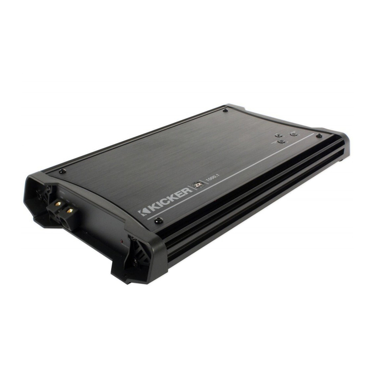
Elektra Mobile Audio Alpha Series User manual

Alpha Series Amplifier Manual
α500.4 Four Channel
α1100.5 Five Channel
α800.1 Monoblock
α1200.1 Monoblock
www.elektramobileaudio.com

ELEKTRA MOBILE AUDIO ALPHA SERIES AMPLIFIER MANUAL
INTRODUCTION
Thank you for choosing ELEKTRA Mobile Audio amplifiers! Your choice of
ELEKTRA Mobile Audio amplifiers indicates a desire for high quality music
reproduction in the automobile. ELEKTRA Mobile Audio brings to you years of car
audio expertise. Whether you are a daily driving music lover, or a serious car audio
competitor, ELEKTRA Mobile Audio has the product for you!
To take full advantage of the ELEKTRA Mobile Audio gear you have just purchased,
please read and follow the instructions in this manual. As with all of our products,
professional installation by an authorized ELEKTRA Mobile Audio dealer is highly
recommended! Be sure to ask your authorized ELEKTRA Mobile Audio dealer
about whether your product may qualify for an extended warranty.
ELEKTRA Mobile Audio amplifiers oer high quality audio reproduction for the
audiophile and the everyday listener alike. All models feature fully variable
crossovers with 12 dB per octave slopes, allowing you the ability to tailor the sound
to best fit the speakers and your listening preferences.
Amplifiers are generally mounted in the hatch/trunk area of a car or SUV, and
under or behind the seat of most pickup trucks. Select a location that will provide
adequate ventilation for the amplifier. Avoid mounting the amplifier with the fins
facing down. The fins should be facing up, either vertically or horizontally. Secure
the amplifier with the screws provided.
www.elektramobileaudio.com

ELEKTRA MOBILE AUDIO ALPHA SERIES AMPLIFIER MANUAL
FEATURES
Platinum finish connections - Ensure solid electrical connections that resist
corrosion.
Fully Variable Crossovers - Fully variable crossovers promote installation ease and
save the cost of outboard crossovers. Additionally, they may be used in conjunction
with outboard passive or active crossovers, depending on the complexity required
by the system. The 12 dB per octave slope oers steep roll-o above or below the
selected frequency.
Protection Circuitry - Overload, Short Circuit, Thermal, Low Voltage, High Voltage,
and Reverse Polarity. These Protection features are designed to protect the
amplifier from misuse, as well as from common causes of amplifier failure.
Design Features:
●IR (International Rectifier) Class-D Topology
●Mini Size Footprint For Easy Installation In Many Applications
●Surface Mount Component Technology
●Audio Precision Quality Control Verification
●Stable & Reliable Four Layers PCB Trace Layout
●Power & Protection & Clipping Led Lights Status Indicator
●Short Circuit, Thermal And Voltage Protection
SAFETY
Before securing the amplifier, inspect the mounting location carefully to ensure
that you do not drill into, or damage any electrical, hydraulic, fluid, or fuel lines.
www.elektramobileaudio.com

ELEKTRA MOBILE AUDIO ALPHA SERIES AMPLIFIER MANUAL
INPUT SECTION
Because of the wide range of head unit output configurations, all ELEKTRA Mobile
Audio amplifiers have an adjustable input sensitivity, "Gain". The gain is not a
volume or a power limiting control like a throttle. It makes the amplifier more
sensitive to input from the stereo. With the gain up, the amplifier will reach full
output at a lower volume setting on the deck. At higher gain settings, the amplifier
also becomes more sensitive to noise from the car's electrical system. Try to run
the gain at the lowest setting possible for your system.
There is no correct gain setting. Because speakers require dierent power
demands to reach the same output, the gains most often need to be used to
compensate for these dierences. If you tried to set all the gains at halfway you
would probably find the system doesn’t sound very good. Using good judgment and
listening carefully to each speaker is still the best way to tune a system.
www.elektramobileaudio.com

ELEKTRA MOBILE AUDIO ALPHA SERIES AMPLIFIER MANUAL
CROSSOVER CONTROLS
A crossover is a device that removes unwanted frequencies from a speaker or
amplifier. A tweeter can easily be destroyed by bass notes if they are not filtered
out. Likewise, a subwoofer will not sound natural if it is playing midrange notes. A
crossover removes these sounds from the speaker. Careful adjustment is needed to
ensure that all the speakers are playing the right sounds and that you are left with
no "holes" or gaps in the frequency response.
SPEAKER OUTPUTS
This amplifier is a multi-channel amplifier design, this means it has more than one
channel of speaker outputs. It is equipped with a large block style terminal for
speaker connections. Make this connection carefully and neatly. Strip your wire
back and twist the exposed leads and insert them into the block terminal while
being careful that there are no loose or frayed strands of wire. Tighten the Allen
head screw down on the terminal until the wire is tightly secured in place. If the
wires ever come in contact with each other the amplifier will go into protection.
www.elektramobileaudio.com

ELEKTRA MOBILE AUDIO ALPHA SERIES AMPLIFIER MANUAL
INSTALLATION INSTRUCTIONS
Ensure that you know your total IMPEDANCE loads before you make any
connections.
1. Before you start, disconnect the negative cable from the car battery. Tape the
exposed end so that it is isolated from the battery.
2. Run an appropriate gauge wire from the battery to the amplifier. Plan this part of
the installation carefully as this cable will carry a very high current. The cable can
cause a fire if it shorts to the body or if it is not properly fused.
3. Connect the power wire to the battery using a fuse capable of the total current
load of all amplifiers connected. Install the fuse after STEP 7. Locate the fuse as
close as possible to the battery. If the fuse is further than 18 inches (wire length)
from the battery you should reevaluate the wire and fuse placement.
4. Find the closest clear metal area to the amplifier for a ground. Sand, grind or
scrape all paint and undercoating from the body and screw the ground securely in
place. It is advisable to test the ground with an ohmmeter between the ground
cable and the negative battery terminal to ensure a good low resistance connection.
Some alloys used in modern cars do not oer the best ground. If you believe this is
the case consult with your installation specialist.
5. Run the speaker wire to the speakers. It is advised that you leave some extra wire
at this point. You can cut the wires to exact length later.
6. If you haven’ t already done so, mount the amplifier to the vehicle now.
7. Connect the power and ground to the amplifier, then you can install the fuse at
the battery.
8. Connect the remote wire from the head unit to the amplifier. This is a good time
to turn on the amplifier for testing. Make sure it turns on properly and does not go
into protection.
9. Turn o the amplifier and connect the speaker wires to the amplifier and
speakers. Make sure the polarity (+ and -) is correct.
10. Connect the RCA'S to the amplifier.
11. Double check the amplifier controls at this time, and adjust if needed.
12. Now you're ready to play the system for the first time. It is best to leave the gain
all the way down at first. Start with the head unit volume low and turn it up.
13. Now you can tune the amplifier. Take your time and make only one adjustment
at a time. It may take some time to get the system fully adjusted. Now have fun!
www.elektramobileaudio.com

ELEKTRA MOBILE AUDIO ALPHA SERIES AMPLIFIER MANUAL
SPECIFICATIONS
Model No.
α500.4
α1100.5
α800.1
α1200.1
RMS POWER
OUTPUT AT 1Ω
-
-
800Wx1CH
1200Wx1CH
RMS POWER
OUTPUT AT 2Ω
240Wx4CH
150Wx4CH+
500Wx1CH
600Wx1CH
1000Wx1CH
RMS POWER
OUTPUT AT 4Ω
125Wx4CH
80Wx4CH+
300Wx1CH
400Wx1CH
600Wx1CH
RMS POWER OUTPUT
AT 4ΩBRIDGED
480Wx2CH
300Wx2CH
-
-
TOTAL HARMONIC
DISTORTION
0.3%
0.3%
0.3%
0.3%
S/N RATIO REF. 1W @ 4Ω
>90dB
>90dB
>90dB
>90dB
GAIN RANGE
0.2-6V
0.2-6V
0.2-6V
0.2-6V
CROSSOVER RANGE
40-4kHz
40-4kHz
Lpf:50-250Hz
Lpf:50-250Hz
FREQUENCY RANGE
20-20kHz
20-20kHz
10-250Hz
10-250Hz
DIMENSIONS (MM)
218x174x49.5
268x174x49.5
198x174x49.5
268x174x49.5
DIMENSIONS (IN)
8.6x6.9x1.9
10.6x6.9x1.9
7.8x6.9x1.9
10.6x6.9x1.9
www.elektramobileaudio.com

ELEKTRA MOBILE AUDIO ALPHA SERIES AMPLIFIER MANUAL
INSTALLATION DIAGRAM - α500.4 FOUR CHANNEL
www.elektramobileaudio.com

ELEKTRA MOBILE AUDIO ALPHA SERIES AMPLIFIER MANUAL
INSTALLATION DIAGRAM - α500.4 FOUR CHANNEL (bridged)
www.elektramobileaudio.com

ELEKTRA MOBILE AUDIO ALPHA SERIES AMPLIFIER MANUAL
INSTALLATION DIAGRAM - α1100.5 FIVE CHANNEL
www.elektramobileaudio.com

ELEKTRA MOBILE AUDIO ALPHA SERIES AMPLIFIER MANUAL
INSTALLATION DIAGRAM - α800.1 & α1200.1 MONOBLOCK
www.elektramobileaudio.com
This manual suits for next models
4
Table of contents
