Elk ELK-M1XRF2G User manual

L614 Rev. C 2/1/11
PO Box 100
3266 US Hwy 70 West
Hildebran, NC 28637
828-397-4200 828-397-4415 Fax
http://www.elkproducts.com
IMPORTANT NOTE:
ELK-M1G and M1EZ8 Controls MUST be operating application firmware ver. 5.0.12 or higher
in order to work with the M1XRF Receiver. Refer to the M1Dealer website for update 'flash' files.
ElkRP Programming Software version 1.6.16 or higher is required for programming the M1XRF.
Do Not update controls that are connected to GE "NX" wireless receivers to 5.x.x firmware. Continue to use
4.x.x firmware with GE receivers. Firmware 5.x.x is ONLY for use with the ELK-M1XRF receiver.
ELK-M1XRF2G
Wireless Receiver and Input Expander
Compatible with specific models of GE Wireless Sensors.
Refer to page 7 for a listing of compatible sensors.
INSTALLATION
MANUAL

Page 2 M1XRF2G Installation Manual
Table of Contents
General Installation and Setup ..................................................................................................... 4
Setting the M1XRF2G Data Bus Address and the Starting Wireless Zone ID .......................................... 5
Data Bus Enrollment:: .............................................................................................................................. 6
Data Bus Address Switches..................................................................................................................... 6
List of GE "Crystal" Wireless Transmitters ................................................................................. 7
Operation and Programming ........................................................................................................ 8
Handling Received Transmissions: .......................................................................................................... 8
Diagnostic LEDs: ..................................................................................................................................... 8
Receiver Setup/Programming and Enrolling of Transmitters: .................................................................. 8
Transmitter (RF) Level Checking [Signal Strength]: ................................................................................. 8
Appendix A - Data Bus Selection Tables ................................................................................... 11
Appendix B - Examples of Zone Configurations ...................................................................... 13
Appendix C - Installing Multiple Redundant Receivers ............................................................ 14
Appendix D - Updating Firmware in the ELK-M1XRF2G .......................................................... 15
This device complies with Part 15 of FCC Rules which are designed to provide reasonable protection against such interference in a residential installation. The FCC
requires the following statement for your information:
This equipment generates and uses radio frequency energy and if not installed and used properly, that is, in strict accordance with the manufacturer’s instructions,
may cause Interference to radio and television reception. It has been type tested. However, there is no guarantee that interference will not occur in a particular
installation. If this equipment does cause interference to radio or television reception, which can be determined by turning the equipment off and on, the user is
encouraged to try to correct the interference by one or more of the following measures:
* If using an indoor antenna, have a quality outdoor antenna installed. * Reorient the receiving antenna until interference is induced or eliminated.
* Move the receiver away from the security control. * Move the antenna leads away from any wire runs to the security control
* Have the device or controller plugged into a different outlet so that it and the receiver are on different branch circuits.
If necessary, the user should consult the dealer or an experienced radio/television technician for additional suggestions. The user or installer may find a booklet titled
“Interference Handbook” prepared by the Federal Communications Commission helpful: This booklet is available from the U.S. Government Printing Office,
Washington, DC 20402. The user shall not make any changes or modifications to the equipment unless authorized by the Installation Instructions or Users Manual.
Unauthorized changes or modifications could void the user’s authority to operate the equipment.
FEATURES:
•Adds up to 144 individual wireless zones (sensors/points)
•Operates from the 4 wire RS485 Data Bus
•Additional Receivers (up to 11) may be Connected to a single M1 or M1EZ8 Control for redundancy or greater coverage
•Flash Memory for Updating of operating Firmware
SPECIFICATIONS:
•Sensitivity: >105 dbm
•Operating Temperature: 0 to +120 degrees F
•Operating Voltage: 12 Volts D.C.
•Current Draw: 70mA
•Indoor Range: 300 to 1000 ft. ** line of sight (For optimum range the ground plane antennas should be installed)
** Walls or metal may reduce actual operating range.

M1XRF2G Installation Manual Page 3
OVERVIEW
The "2G" model of the ELK-M1XRF Wireless RF Receiver (full part # ELKM1XRF2G) allows the ELK-M1 and ELK-M1EZ8 Controls
to accept specific models of GE wireless transmitters. The receiver connects to the four (4) wire data (keypad) bus of the control
and integrates in much the same way as a M1XIN hardware zone expander except that a single Receiver can handle up to 144
wireless zones (e.g. transmitter sensors or points). The benefits of operating from the data bus are: 1) A receiver can be installed
virtually anywhere in the building for convenience and optimum coverage. 2) Multiple receivers (up to 11 total) can be connected
to a single control for ultimate range and/or coverage redundancy. The major benefit of having multiple Receivers is that hundreds
if not thousands of square feet can now be covered by strategically placing each receiver in a different geographic location.
The M1XRF receiver is designed such that all transmitter programming and enrollment data is stored in the control panel, and not
in the receiver itself. This way, should a receiver ever need to be replaced, it is only necessary to enroll the replacement receiver
onto the data bus and then enter and exit the wireless setup programming. In addition, portable devices like Keyfobs can work
with multiple receivers on the same system. Regardless of which receiver picks up the Keyfob transmission, the data will be sent
back to the panel for processing.
The ELK-M1Gold or M1EZ8 MUST be operating firmware 5.0.12 or higher.
ElkRP Programming Software version 1.6.16 or higher is required for programming.
NOTE: The "2G" suffix on the M1XRF part number refers to "2 antenna" & "GE" compatibility. The
M1XRF2G is ONLY compatible with specific models of GE 319.5MHz transmitters, and ONLY those
sensors which utilize Crystal technology.
This receiver incorporates Crystal frequency technology and is a dual (2) antenna, phase diversity design capable of long range
wireless coverage. It comes packaged with two (2) optional ground plane antennas for extremely long range coverage
requirements.
NOTE: GE makes both Crystal and SAW technology transmitters in the 319.5MHz range. Crystal
technology has very narrow frequency tolerances and utilizes highly accurate filtering technology to
reduce noise susceptibility and provide the best possible range. SAW technology has a broader
frequency tolerance making them less costly and less accurate, generally resulting in shorter range.
The use of SAW transmitters with any Crystal based receiver is not a good practice due to the fact that
the broader frequency SAW transmission may be filtered out (ignored) by the narrower Crystal receiver.
While it may be possible to get a SAW transmitter to enroll into the M1XRF receiver IT IS NOT
RECOMMENDED due to the possibility of a transmission being filtered out (ignored).
Page 4 M1XRF2G Installation Manual
General Installation and Setup
1. Mounting - Two (2) #6 x 1/2" screws (not provided), one on each side of the housing should be used for mounting. The
M1XRF connects to the M1's Keypad data bus and may be remotely located up to several thousand feet away from the
control. Mounting inside a metal enclosure or on metalized wallpaper is NOT RECOMMENDED! Try and mount at least
10 feet away from any electrical device that generates noise including the M1 Control as electrical noise may reduce the
receiver sensitivity. For increased signal coverage or redundancy additional M1XRF Receivers (up to 12 max.) may be
connected to the same M1 Controller. See Appendix C.
2. Wiring Connections - Before making any wiring connections, turn the power Off on the Control Panel. Connect
terminals +12V, A, B, and Neg from the M1XRF to the M1's Keypad Data Bus (terminals +VKP, Data A, Data B, & Neg).
NOTE: Refer to the M1 Installation Manual and the M1DBH information in this manual about proper
connections of data bus devices with multiple homerun cables.
3. Antenna Installation
M1XRF2G is supplied with four (4) antennas. Two (2) of these antennas installed into the top locations marked Antenna1
& Antenna 2 will be more than adequate for proper receiver performance. The dual antennas ensure signal diversity
which helps eliminate RF dead spots. The two (2) extra antennas are called Ground Plane Antennas. In extreme
applications or where maximum range is desired these additional antennas can be installed in the bottom locations
marked Antenna 3 & Antenna 4.
NOTE: Each antenna location has a two (2) position screw terminal block. MAKE SURE to insert and tighten the
antennas into the screw terminals marked ANTENNA. Do not use the adjacent screw terminal.
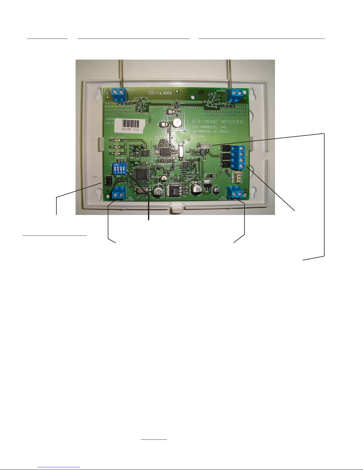
INSTALL UNIT * SET ADDRESS AND OPTION JUMPERS * ACTIVATE M1 BUS ENROLLMENT PROCESS
RS-485
Data Bus
Connections
Data Bus Address Switches
Dual Antennas
Antenna 2
NOTE: Jumper JP1may be used to terminate the RS-485 Data Bus if this is the last installed device.
Optional Ground Plane Antennas 3 & 4
ELK-M1XRF2G
Antenna 1
J1 * Factory Use ONLY *
DO NOT PUT JUMPERS ON J1
DAMAGE MAY RESULT.

M1XRF2G Installation Manual Page 5
Devices that communicate on the RS-485 4-wire data bus must each have a valid address setting (from 1 to 15) within
their device type. Keypads are TYPE 1, Hardwire and Wireless Input expanders are TYPE 2, Output expanders TYPE 3,
Serial expanders TYPE 4. The device types allow address numbers to be re-used in each different device type. There are
4 address switches, each with an OFF or ON position (binary value 0 or 1) and decimal equiv. value of (1, 2, 4, or 8). The
total decimal value of the "ON" switches determines the data bus address. Set the switches to the desired data bus
address by referring to Tables 1-1 and 1-2. A small screwdriver may be helpful. See important information before
proceeding to "Data Bus Enrollment".
VERY IMPORTANT! PLEASE READ!
Due to Hardwire and Wireless expanders sharing the same device type and same bus address range,
unintentional data bus "Conflicts" are possible with M1XRF Wireless Receiver(s) and M1XIN Hardwired
Expander(s) installed on the same control. These conflicts can be avoided with proper understanding of
the issues and careful planning and execution during installation. The important point to remember is
that M1XRF Wireless Receivers and M1XIN Zone Expanders share the same data bus addresses. Below
are some issues and recommendations to avoid addressing conflicts:
M1XIN Expanders: A single ELK-M1XIN Hardwired Zone Expander (M1XIN) provides 16 hardwired zones. The data bus
address SETS THE ID OF THE STARTING ZONE of each 16 zone group. See Table 1-1. If additional M1XINs are installed,
each must have a different address (usually the next available) to set the starting zone of the next 16 zone group. I.E., Each data
bus address equates to a specific group of 16 zone IDs. Everything works fine as long as there are NO DUPLICATE addresses.
M1XRF Receivers: The main differences between a Wireless Receiver and a ELK-M1XIN Zone Expander are:
1) Using only a single (1) Wireless Receiver it is possible to add up to 144 wireless zones to the control in groups of 16 at
a time. However, in order to have 144 total wireless zones the first group of 16 must begin at zone 17 and the rest of the
wireless zones must be sequential through zone 160. Caution! If any hardwired zone expanders are enrolled in the
range of zones 17 through 160 then 16 wireless zones will be lost for every hardwired (16 zone) expander.
2) It is possible to have multiple M1XRF Wireless Receivers installed for added range and coverage redundancy. The
"redundant" receivers can be assigned to any unused data bus address. For this reason the data bus address of an
Wireless Receiver does not actually determine the starting wireless zone number. Even so, for the sake of simplicity,
installers are encouraged to set the data bus address of the first M1XRF Receiver (if there are multiple Receivers) to the
starting zone ID as depicted in Tables 1-1 and 1-2.
NOTE: ELK strongly recommends that the starting wireless zone number conforms to the numbering scheme shown
in Tables 1-1 and 1-2, even though the actual data bus address of the M1XRF could be address 10 while the first
group of 16 wireless zones could be programmed as 17-32. Although there may be some benefits to being able to
program the starting zone without regard to the data bus address, the disadvantages are potential zone numbering
conflicts when M1XIN Hardwired Zones Expanders exist. For the sake of simplicity, installers are encouraged to
set the starting zone ID and the M1XRF data bus address to conform to the conventional settings used by the
hardwired zone expanders. Refer to Tables 1-1 and 1-2 on opposite page.
Other important considerations when installing an M1XRF:
a) From a system standpoint wireless zones should be considered to be minimum blocks of 16 zones, even though all of
the 16 zones do not necessarily need to be utilized.
b) Care must be taken to ensure that wireless zones NEVER spill over into data bus addresses that are already assigned
to or in use by a M1XIN Hardwired Zone Expander and vs. versa,
c) Regardless of where the wireless zones start we strongly suggest that all additional wireless zones be contiguous and
that no M1XIN Hardwired Zone Expanders be installed at data bus addresses associated with those wireless zone
numbers. Data Bus Addresses whose zone IDs are effectively "overlapped" by wireless zones are considered
"reserved" for wireless use and should not be used by a hardwired zone expander. See Appendix C.
d) The last wireless zone number cannot be above 160. Basically, zones 161 through 208 cannot be wireless zones.
e) The maximum number of wireless zones is 144, therefore the last wireless zone number cannot be greater than 160.
Example: Let's say the starting wireless zone ID is set to "17" (associated with data bus address 2) and you decide to
create 64 contiguous zones starting from 17. That means that zones 17 to 31, 32 to 48, 49 to 64, and 65 to 80 are going to be
wireless zones. Based on Tables 1-1 and 1-2 it is easy to see that zones 17 to 31 are associated with data bus address 2
and zones 32 to 48, 49 to 64, and 65 to 80 are associated with data bus addresses 3, 4, and 5 respectively. Based on this,
addresses 3,4, and 5 are NOT AVAILABLE for use by M1XIN Expanders because the wireless zones are overlapping these
addresses.
NOTE: Consider whether the system may ever required more wireless or hardwired zones. If the answer is yes it
would be good to plan the data bus address assignments in such a way that future growth is possible without having
to default the control or totally re-arrange the addresses at a future date.
Setting the M1XRF Data Bus Address and the Starting Wireless Zone ID
Page 6 M1XRF2G Installation Manual
Switch Settings
S1 S2 S3 S4
Off On Off Off
On On Off Off
Off Off On Off
On Off On Off
Off On On Off
On On On Off
Off Off Off On
On Off Off On
Off On Off On
--- -
--- -
--- -
--- -
--- -
Data Bus
Address
2
3
4
5
6
7
8
9
10
11
12
13
14
15
Other Jumper
Settings:
JP1 - Used to
engage a 120
Ohm resistor for
terminating the
RS-485 Data Bus.
See Data bus
wiring instructions
before use.
Suggested Wireless
"Starting Point"
Zone 17
Zone 33
Zone 49
Zone 65
Zone 81
Zone 97
Zone 113
Zone 129
Zone 145
not valid
not valid
not valid
not valid
not valid
Switch Settings
S1 S2 S3 S4
Off On Off Off
On On Off Off
Off Off On Off
On Off On Off
Off On On Off
On On On Off
Off Off Off On
On Off Off On
Off On Off On
On On Off On
Off Off On On
On Off On On
--- -
--- -
Data Bus
Address
2
3
4
5
6
7
8
9
10
11
12
13
14
15
Starting and Ending
Zone Numbers
Zones 17 - 32
Zones 33 - 48
Zones 49 - 64
Zones 65 - 80
Zones 81 - 96
Zones 97 - 112
Zones 113 - 128
Zones 129 - 144
Zones 145 - 160
Zones 161 - 176
Zones 177 - 192
Zones 193 - 208
not valid
not valid
Table 1-1 Table 1-2
M1XRF2G Wireless ReceiversM1XIN Zone Expanders
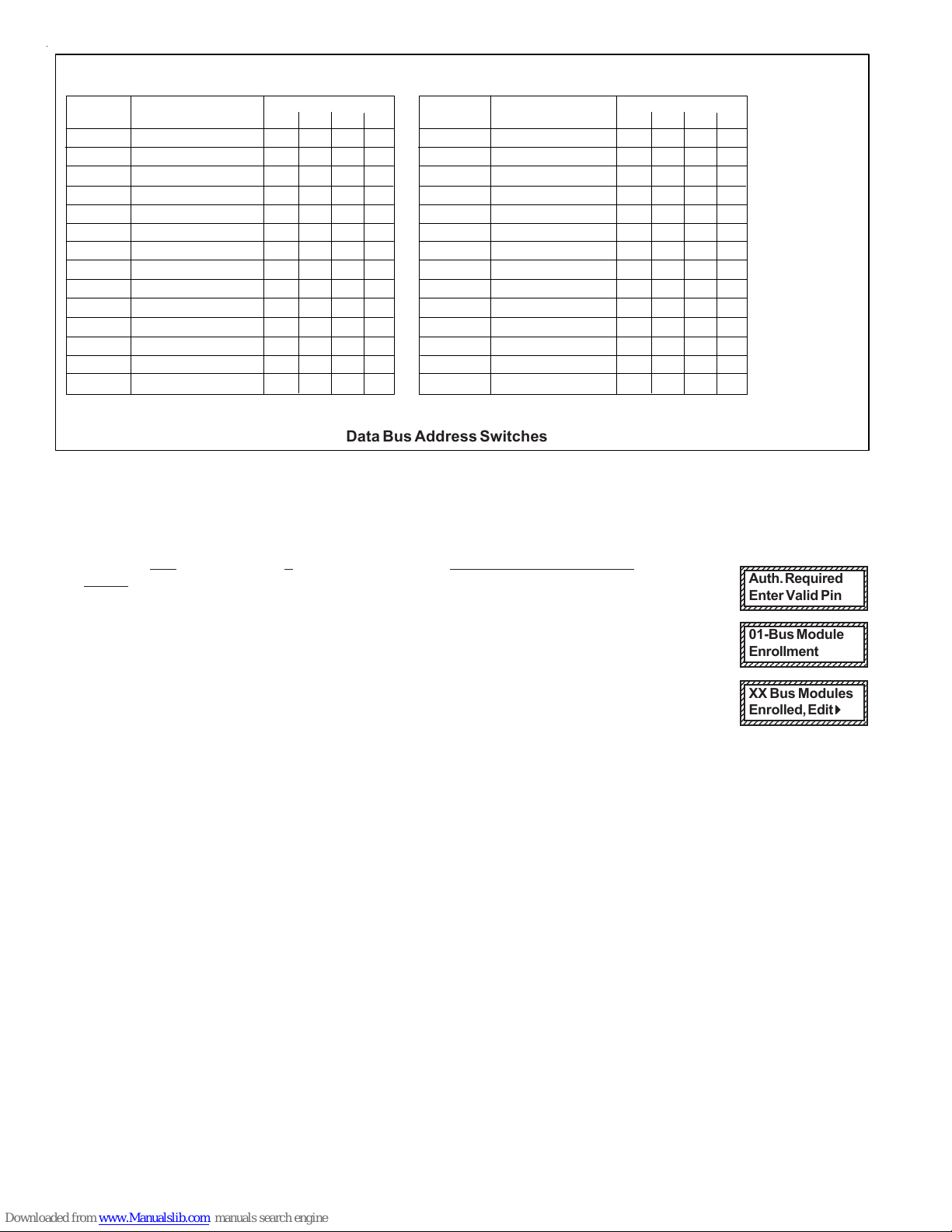
Data Bus Enrollment::
Once the address is set and the M1XRF2G is powered up it will be necessary to manually ENROLL the device so that the M1
Control knows it is present. This is accomplished either from keypad programming "Menu 1 - Bus Module Enrollment" or
from the ElkRP Remote Programming Software.
(The steps below require an M1 LCD Keypad)
1. Press the ELK key, then press 9 (or scroll up) to display 9 - Installation Programming. Press the
RIGHT arrow key to select this menu. The Installer Program Code (PIN) must be entered to access
this menu.
2. Enter the Installer Program Code. (The default code is 172839)
3. The first Installer Programming menu displayed will be "Bus Module Enrollment"
4. Press the RIGHT arrow key to select this menu. "Enrolling Bus Modules" will display
5. The control will transmit an enrollment message to all data bus devices, followed by a display
showing the total Bus Modules that are enrolled. To view the enrolled devices and/or remove a
device press the RIGHT arrow key next to the word Edit.
6. Press the * or Exit keys to exit Installer Programming.
12345678901234567890123456
1
234567890123456789012345
6
1
234567890123456789012345
6
1
234567890123456789012345
6
1
234567890123456789012345
6
1
234567890123456789012345
6
1
234567890123456789012345
6
1
234567890123456789012345
6
1
234567890123456789012345
6
12345678901234567890123456
XX Bus Modules
Enrolled, Edit rr
rr
r
12345678901234567890123456
1
234567890123456789012345
6
1
234567890123456789012345
6
1
234567890123456789012345
6
1
234567890123456789012345
6
1
234567890123456789012345
6
1
234567890123456789012345
6
1
234567890123456789012345
6
1
234567890123456789012345
6
12345678901234567890123456
Auth. Required
Enter Valid Pin
12345678901234567890123456
1
234567890123456789012345
6
1
234567890123456789012345
6
1
234567890123456789012345
6
1
234567890123456789012345
6
1
234567890123456789012345
6
1
234567890123456789012345
6
1
234567890123456789012345
6
12345678901234567890123456
01-Bus Module
Enrollment
Data Bus Address Switches

M1XRF2G Installation Manual Page 7
List of GE "Crystal" Wireless Transmitters
This list was compiled from the latest manufacturer's provided information. Elk Products makes no assurances
as to the accuracy of this information. All information is subject to change without notice.
Enroll Process - For units with tamper supervision activate the tamper, otherwise press the front Test button,
Test Button can also be used to transmit a violation (alarm) 2
Smoke Detector
GE part # 60-848-02-95, or equivalent >OPTIONS - WZnxxx 03 (Option 1) For units with tamper supervision this option MUST BE set to YES.
For units without tamper supervision this option MUST BE set to NO
Enroll Process - Press Main Button 3
Single Button Wrist/Pendant Panic
GE part # 60-906-95, or equivalent >OPTIONS - None
Enroll Process - Press Main Button 3
Single Button Pendant Panic
GE part # 60-578-10-95, or equivalent >OPTIONS - None
Enroll Process - Remove back cover / activate tamper switch
Note: Transmitter does not send restores. Control automatically assumes restoral 8 seconds after violation. 4
PIR Motion Detector
GE part # 60-880-95, or equivalent >OPTIONS - None
Enroll Process - Press Test Button or Tamper Switch
A
Door And Window Transmitter
GE part #'s 60-362-10-319.5,
60-641-95, or equivalent >OPTIONS - WZnxxx 03 (Option 1) set to YES to disable internal Reed Switch. NO leaves the internal switch active.
>OPTIONS - WZnxxx 04 (Option 2) set to YES to use a N/C Switch on External Contacts, NO to use a N/O Switch.
Enroll Process - Remove back cover / activate tamper switch
Note: Transmitter does not send restores. Control automatically assumes restoral 8 seconds after violation. 4
PIR Motion Detector
GE part #' 60-703-95, or equivalent >OPTIONS - None
Enroll Process - Remove back cover / activate tamper switch
Note: Transmitter does not send restores. Control automatically assumes restoral 8 seconds after violation. 4
PIR Motion Detector
GE part # 60-511-01-95, or equivalent >OPTIONS - None
Enroll Process - Press Test Button or Tamper Switch
5
Door And Window Transmitter
GE part # 60-499-10-319.5,
or equivalent >OPTIONS - WZnxxx 03 (Option 1) set to YES to disable internal Reed Switch. NO leaves the internal switch active.
>OPTIONS - WZnxxx 04 (Option 2) set to YES to use a N/C Switch on External Contacts, NO to use a N/O Switch.
Enroll Process - Twist end cap using a coin or screwdriver 1/8" CCW
A
Door And Window Transmitter
GE part # 60-688-95, or equivalent >OPTIONS - WZnxxx 03 (Option 1) set to YES to disable internal Reed Switch. NO leaves the internal switch active.
>OPTIONS - WZnxxx 04 (Option 2) set to YES to use a N/C Switch on External Contacts, NO to use a N/O Switch.
Enroll Process - Press Test Button or Tamper Switch
A
Door And Window Transmitter
GE part # 60-741-95, or equivalent >OPTIONS - WZnxxx 03 (Option 1) set to YES to disable internal Reed Switch. NO leaves the internal switch active.
>OPTIONS - WZnxxx 04 (Option 2) set to YES to use a N/C Switch on External Contacts, NO to use a N/O Switch.
Enroll Process - Press Test Button located on circuit board inside the unit next to the battery
6
Heat 'Rate Of Rise' Transmitter
GE part # 60-460-319.5, or equivalent >OPTIONS - None
Enroll Process - Activate Tamper Switch
9
Glass Break Transmitter
GE part # 60-873-95, 60-834-95, or
equivalent >OPTIONS - WZnxxx 04 (Option 2) MUST be set to YES
Enroll Process - Press Test Button
9
Shock Sensor
GE part # 60-886-95, or equivalent >OPTIONS - WZnxxx 04 (Option 2) MUST be set to YES
Enroll Process - Press Button
B
Single Button Large Panic Transmitter
GE Part # 60-458-10-319.5, or
equivalent >OPTIONS - None
Enroll Process - Press Button D
Glass Guard Transmitter
GE Part # 6046210319.5 >OPTIONS - None
Enroll Process - Press Test Button
E
Freeze Sensor Transmitter
GE Part # 60-504-10-95R,
or equivalent >OPTIONS - None
Enroll Process - Press and hold the Lock and Unlock Buttons (buttons 1 & 2) together at the same time.
F
Four Button Keyfob Transmitter
GE Part # 60-606-319.5, or equivalent
>OPTIONS - WZnxxx 03 (Option 1) set to YES swaps the action of the Light button from Key=3 to Key=5.
>OPTIONS - WZnxxx 04 (Option 2) set to YES swaps the action of the Asterisk button from Key=4 to Key=6
Note: Pressing the Lock and Unlock buttons together momentarily triggers the event assigned to Key 7.
Pressing the Light and Asterisk buttons together momentarily triggers the event assigned to Key 8.
Device Part Number(s) Special Info **
** The first digit of the transmitter's ID code should begin with this alphanumeric character. It is the transmitter "type" or ID and is used internally by the receiver to
determine what options or setup pertain to the transmitter.

Page 8 M1XRF2G Installation Manual
Handling Received Transmissions:
Operationally when a transmitter signal is received by the M1XRF2G it quickly scans through a filter of valid transmitter
sensors to determine if it that sensor has been enrolled into the M1 or EZ8 control. If that transmitter is valid then its data will
be sent to the M1 Controller for additional processing. The M1 Controller automatically informs any additional Receivers that it
has received this transmitter, just in case they also heard the same transmission. This handling procedure does two things.
It eliminates duplicate signal processing while allowing multiple receivers for improved range and reliability. It also helps
prevent unwanted or neighboring transmitters belonging to another system from being duplicated on the data bus.
Operation and Programming
Diagnostic LEDs:
Three (3) Status LEDs provide valuable information as to the operation of the M1XRF2G:
"ORANGE" STATUS LED - This LED has multiple purposes as outlined below:
OFF = No Power to the M1XRF2G
ON Solid = The M1XRF2G is powered but it is either Not Enrolled or the Microprocessor is not functioning.
BLINKING = There are 2 possible blinking rates:
- A slow blink of once per second with a matching Off time indicates normal operating mode.
- A more rapid "two" blinks per second with a very brief Off time indicates the M1XRF2G is in Bootloader mode.
This occurs when the unit is awaiting a flash download of its application firmware. Until the firmware
application has been successfully downloaded the M1XRF2G is non-functional as a wireless receiver.
"GREEN" VALID LED - This LED will momentarily turn on whenever the M1XRF2G receives a valid "enrolled" transmitter and it
is in the process of sending the signal packet back to the M1 Controller. As soon as the packet is acknowledged by the
M1 Controller the LED will turn Off.
"YELLOW" RF LED - This LED will blink whenever the M1XRF2G hears ANY GE/Caddx/ITI transmitter signal, regardless of
whether the transmitter is valid. This only means that a transmitter was received, it does not mean that the signal is
being sent back to the M1 Controller. Refer to Valid LED above and the section titled "Handling of Received Signals".
Receiver Setup/Programming and Enrolling of Transmitters:
The Receiver and wireless transmitters may be programmed using either the M1 Keypad Installer Programming or the ElkRP
Remote Programming software. The following pages document the options and steps for programming from the keypad.
Transmitter (RF) Level Checking [Signal Strength]:
Wireless transmitters send multiple repeats "or rounds" of their data transmission packets to compensate for interfer-
ence, weak signal, etc. In the case of GE Transmitters, Intrusion type sensors send 8 repeats "rounds", Fire type
sensors send 16 repeats, and Panic type sensors send 12 repeats. These repeated packets are also useful to the
receiver in providing level checking [signal strength, walk test, etc.} as a reference of the acceptable reliability of the
sensor and it's mounting orientation and/or location.
When the M1XRF2G receiver first hears a wireless transmission, it tracks and totals the number of received data pack-
ets over the next 10 seconds. During keypad enrollment of a new transmitter, the total number of received packets is
voice announced by the M1 immediately following the successful enrollment. The number is also voice announced
during the Keypad Walk Test of a Wireless zone. For Example: If all data packets from an Intrusion sensor (8 out of a
total of 8) were properly detected you should hear "Sensor X, Level 8". This would indicate the highest signal strength for
this particular Intrusion Sensor.
In Elk's opinion, the minimum acceptable level of any wireless sensor would generally be a level 4. This is based on
the fact that the Receiver REQUIRES a minimum of 2 repeated data packets in order to qualify an event as a valid
transmission. Level 4 is just a rule of thumb based on doubling the minimum required number of repeated data pack-
ets. It is the responsibility of the installation company and their technicians to adopt their own policy of what should
constitute a minimum acceptable level [signal strength] of any wireless transmitter.
IMPORTANT: Because the Receiver counts all valid data packets received over a 10 second time window, it is possible
to occasionally hear a number that is much higher than the number you might expect to hear from a particular sensor.
This can occur when multiple transmitters on a site happen to transmit at the same time as the one being tested.
Based on the type of RF sensor being tested, if the announced value is too high or just sounds wrong or inconsistent, ,
it is recommended that you retest or retrigger that sensor to get a more correct data packet decode level.
M1XRF2G Installation Manual Page 9
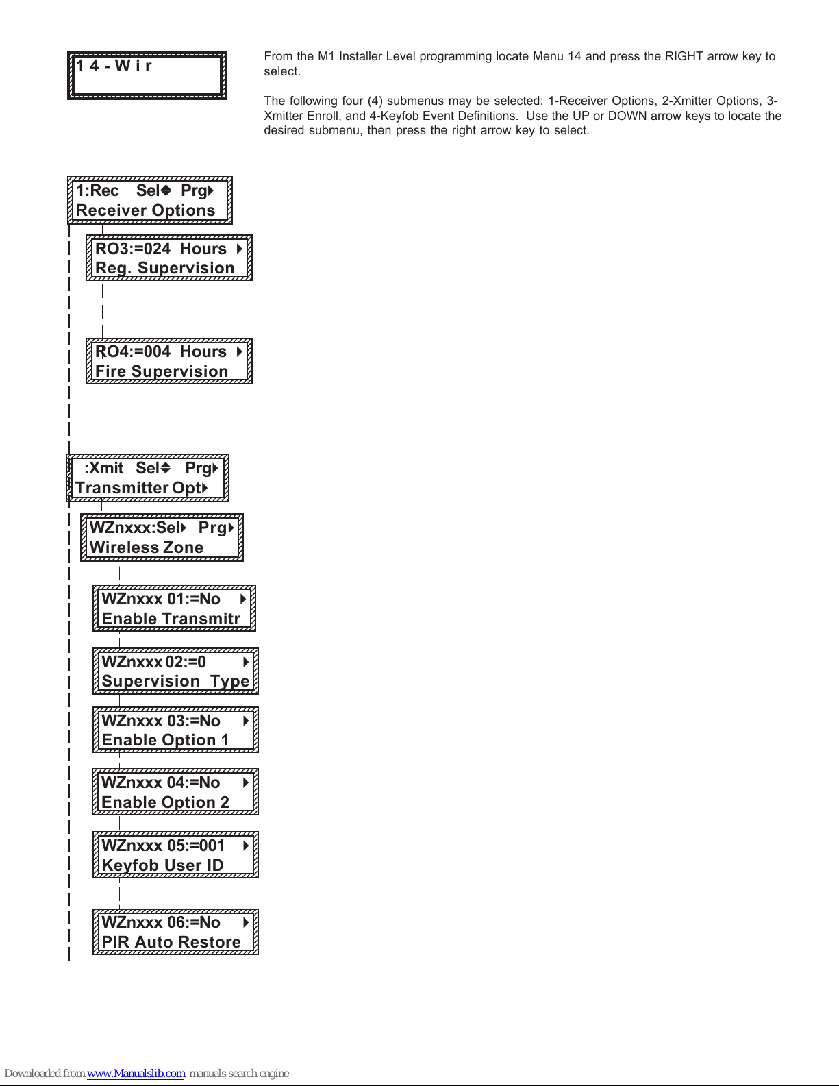
Wireless Setup Description
Press the right arrow to select Receiver Options.
Rec. Option R03: Reg. Supervision is for "non-fire" transmitters, i.e. transmitters programmed
as "Supervisory Type 1" (see Xmit Transmitter Opt 02 below). The time setting for this
determines how often a sensor must check-in with the control in order to supervise its
presence. The programmable range is 001 to 255 hours. Should a sensor fail to check-in
prior to the expiration of each interval it will be considered "missing". NOTE: A value less than
4 hours is NOT RECOMMENDED! Factory default setting is 024 hours.
Rec. Option R04: Fire Supervision is for "fire" type transmitters, i.e. transmitters programmed
as "Supervisory Type 2" (see Xmit Transmitter Opt 02 below). The time setting for this
determines how often a sensor must check-in with the control to supervise its presence.
Range is 001 to 255 hours. Should a sensor fail to check-in prior to the expiration of each
interval it will be considered "missing". NOTE: A value less than 4 hours is NOT
RECOMMENDED! Factory default setting is 004 hours.
Press the RIGHT arrow key to select 2:Xmit Transmitter Opt.
Use the UP and DOWN arrow keys to locate a particular wireless transmitter. Press the
RIGHT arrow key to select and program the displayed transmitter.
WZnxxx 01 displays whether transmitter xxx is enabled or disabled. It can be used to
temporarily disable an existing enrolled device. It cannot be used to add a new device. This
can only be done via the "learn" or enroll process which then sets this location to a Yes.
WZnxxx 02 is used to select the type of supervision for transmitter xxx. 0 - (No Supervision),
1 - (Regular Supervision), 2 - (Fire Supervision). See receiver selections R02 and R03 for
supervision time values. Factory default setting is 1 (Regular Supervision).
WZnxxx 03 is used to select functionality traits "options" for certain types of GE Transmitter
Devices. IMPORTANT: Refer to the Listing of GE "Crystal" Transmitters on
previous page for any devices that utilize or require these options.
WZnxxx 04 is used to select functionality traits "options" for certain types of GE Transmitter
Devices. IMPORTANT: Refer to the Listing of GE "Crystal" Transmitters on
previous page for any devices that utilize or require these options.
WZnxxx 05 is used to set the User ID that will be logged for a transmitter which is a Keyfob
when that Keyfob is used to arm of disarm. Valid range is 001 to 255. Numbers 001 to 199
mirror the keypad user codes. Note: Opening and closing reports may be programmed for
every User code.
WZnxxx 06 is currently NOT required with GE Wireless PIR Motion sensors. It may be used in
the future. * FYI: To conserve battery power almost all Wireless PIR Motion sensors transmit
alarms only, no restorals. Therefore, the panel or receiver must assume a restoral condition
from these sensors after a short time delay. Wireless PIRs also conserve power by only
detecting and transmitting once is a several minute time cycle. They remain quiet until the
time cycle expires, regardless of motion in the room. For this reason Wireless PIRs are not
very practical for most automation or occupancy detection applications.
1234567890123456789012345678901212345
1
23456789012345678901234567890121234
5
1
23456789012345678901234567890121234
5
1
23456789012345678901234567890121234
5
1
23456789012345678901234567890121234
5
1
23456789012345678901234567890121234
5
1
23456789012345678901234567890121234
5
1
23456789012345678901234567890121234
5
1
23456789012345678901234567890121234
5
1
23456789012345678901234567890121234
5
1234567890123456789012345678901212345
1:Rec SelbPrgr
Receiver Options
1234567890123456789012345678901212345
1
23456789012345678901234567890121234
5
1
23456789012345678901234567890121234
5
1
23456789012345678901234567890121234
5
1
23456789012345678901234567890121234
5
1
23456789012345678901234567890121234
5
1
23456789012345678901234567890121234
5
1
23456789012345678901234567890121234
5
1
23456789012345678901234567890121234
5
1
23456789012345678901234567890121234
5
1234567890123456789012345678901212345
RO4:=004 Hours r
Fire Supervision
From the M1 Installer Level programming locate Menu 14 and press the RIGHT arrow key to
select.
The following four (4) submenus may be selected: 1-Receiver Options, 2-Xmitter Options, 3-
Xmitter Enroll, and 4-Keyfob Event Definitions. Use the UP or DOWN arrow keys to locate the
desired submenu, then press the right arrow key to select.
123456789012345678901234567890121234
1
2345678901234567890123456789012123
4
1
2345678901234567890123456789012123
4
1
2345678901234567890123456789012123
4
1
2345678901234567890123456789012123
4
1
2345678901234567890123456789012123
4
1
2345678901234567890123456789012123
4
1
2345678901234567890123456789012123
4
1
2345678901234567890123456789012123
4
1
2345678901234567890123456789012123
4
123456789012345678901234567890121234
14-Wireless
Setup r
† Not evaluated by UL
123456789012345678901234567890121234
1
2345678901234567890123456789012123
4
1
2345678901234567890123456789012123
4
1
2345678901234567890123456789012123
4
1
2345678901234567890123456789012123
4
1
2345678901234567890123456789012123
4
1
2345678901234567890123456789012123
4
1
2345678901234567890123456789012123
4
1
2345678901234567890123456789012123
4
1
2345678901234567890123456789012123
4
1
2345678901234567890123456789012123
4
123456789012345678901234567890121234
2:Xmit Selb Prgr
Transmitter Optr
1234567890123456789012345678901212345
1
23456789012345678901234567890121234
5
1
23456789012345678901234567890121234
5
1
23456789012345678901234567890121234
5
1
23456789012345678901234567890121234
5
1
23456789012345678901234567890121234
5
1
23456789012345678901234567890121234
5
1
23456789012345678901234567890121234
5
1
23456789012345678901234567890121234
5
1
23456789012345678901234567890121234
5
1234567890123456789012345678901212345
WZnxxx 04:=No r
Enable Option 2
123456789012345678901234567890121234
1
2345678901234567890123456789012123
4
1
2345678901234567890123456789012123
4
1
2345678901234567890123456789012123
4
1
2345678901234567890123456789012123
4
1
2345678901234567890123456789012123
4
1
2345678901234567890123456789012123
4
1
2345678901234567890123456789012123
4
1
2345678901234567890123456789012123
4
1
2345678901234567890123456789012123
4
123456789012345678901234567890121234
WZnxxx 01:=No r
Enable Transmitr
1234567890123456789012345678901212345
1
23456789012345678901234567890121234
5
1
23456789012345678901234567890121234
5
1
23456789012345678901234567890121234
5
1
23456789012345678901234567890121234
5
1
23456789012345678901234567890121234
5
1
23456789012345678901234567890121234
5
1
23456789012345678901234567890121234
5
1
23456789012345678901234567890121234
5
1234567890123456789012345678901212345
WZnxxx 02:=0 r
Supervision Type
1234567890123456789012345678901212345
1
23456789012345678901234567890121234
5
1
23456789012345678901234567890121234
5
1
23456789012345678901234567890121234
5
1
23456789012345678901234567890121234
5
1
23456789012345678901234567890121234
5
1
23456789012345678901234567890121234
5
1
23456789012345678901234567890121234
5
1
23456789012345678901234567890121234
5
1
23456789012345678901234567890121234
5
1234567890123456789012345678901212345
WZnxxx 03:=No r
Enable Option 1
1234567890123456789012345678901212345
1
23456789012345678901234567890121234
5
1
23456789012345678901234567890121234
5
1
23456789012345678901234567890121234
5
1
23456789012345678901234567890121234
5
1
23456789012345678901234567890121234
5
1
23456789012345678901234567890121234
5
1
23456789012345678901234567890121234
5
1
23456789012345678901234567890121234
5
1
23456789012345678901234567890121234
5
1234567890123456789012345678901212345
RO3:=024 Hours r
Reg. Supervision
123456789012345678901234567890121234
1
2345678901234567890123456789012123
4
1
2345678901234567890123456789012123
4
1
2345678901234567890123456789012123
4
1
2345678901234567890123456789012123
4
1
2345678901234567890123456789012123
4
1
2345678901234567890123456789012123
4
1
2345678901234567890123456789012123
4
1
2345678901234567890123456789012123
4
1
2345678901234567890123456789012123
4
1
2345678901234567890123456789012123
4
123456789012345678901234567890121234
WZnxxx:SelrPrgr
Wireless Zone
1234567890123456789012345678901212345
1
23456789012345678901234567890121234
5
1
23456789012345678901234567890121234
5
1
23456789012345678901234567890121234
5
1
23456789012345678901234567890121234
5
1
23456789012345678901234567890121234
5
1
23456789012345678901234567890121234
5
1
23456789012345678901234567890121234
5
1
23456789012345678901234567890121234
5
1
23456789012345678901234567890121234
5
1234567890123456789012345678901212345
WZnxxx 05:=001 r
Keyfob User ID
1234567890123456789012345678901212345
1
23456789012345678901234567890121234
5
1
23456789012345678901234567890121234
5
1
23456789012345678901234567890121234
5
1
23456789012345678901234567890121234
5
1
23456789012345678901234567890121234
5
1
23456789012345678901234567890121234
5
1
23456789012345678901234567890121234
5
1
23456789012345678901234567890121234
5
1
23456789012345678901234567890121234
5
1234567890123456789012345678901212345
WZnxxx 06:=No r
PIR Auto Restore

Page 10 M1XRF2G Installation Manual
Choose the ZONE to enroll a new transmitter by entering the three (3) digit zone number OR
by scrolling the UP and DOWN arrow keys. Press the RIGHT arrow key to select and program
that zone.
This message will display and the M1 will speak: "Press Transmitter Button for Zone XXX",
UNLESS a transmitter is already enrolled (see below). Proceed to the transmitter and execute
the enroll process. I.E. Press the tamper button, etc. The keypad will chime and the M1 will
speak: "[Zone Name] Enrollment" if successful. It will also speak a number indicating the
relative strength of the last transmission. Refer to section titled "Transmitter Level Checking."
This display shows the zone number and ID of the enrolled transmitter. NOTE: After a new
transmitter is enrolled the control automatically advances to the next zone number and the M1
speaks "Press Transmitter Button for Zone XXX". This permits rapid enrollment of additional
transmitters in sequential order. When transmitter enrollment is complete press the ELK key
twice to exit the enrollment and return to the other menus.
IMPORTANT! If it becomes necessary to delete or replace an existing transmitter you must
use the transmitter option "WZnxxx 01" and select "No" to disable the existing transmitter.
This menu is used to program the operation or "action" that a keyfob button will perform. A GE
four (4) button keyfob can be assigned up to six (6) separate operations as explained below.
To select this menu press the RIGHT arrow key.
Press the UP or DOWN arrow keys to select a key (1 to 8). There are 8 possible keys but only
6 of them can be used. The definition or operation is programmed using a four (4) digit event
code derived from the Zone Definitions table located in the M1 Installation Manual. The range
is 0000 to 0030 See M1 Installer Manual, Appendix A, Event Codes.
Each of the four (4) buttons on a GE Keyfob has a printed symbol and the M1 programming
has the following default event (operation) assigned to these buttons:
Key Symbol M1 Default Value Operation
Lock {Key=1} Event=0027 KeyMomAway (Arm the Control)
Unlock {Key=2} Event=0029 KeyMomDisarm (Disarm the Control)
Light {Key=3 Event=0000 "No default function"
Asterisk {Key=4} Event=0000 "No default function"
ALTERNATE KEY FUNCTIONS
The operation of the Light and Asterisk symbol buttons can be altered by selection of the
transmitter option "WZnxxx 03" and "WZnxxx 04". Refer to the previous page.
Example of a keyfob transmitter enrolled at Zn017:
Setting WZn017 03: {Option1} to NO makes the Light button trigger the event assigned to
Key=3. Setting WZn017 03: {Option1} to YES makes the Light button trigger the event as-
signed to Key=5 instead. Effectively swaps Key 3 for Key 5.
Setting WZn017 04: {Option2} to NO makes the Asterisk button trigger the event assigned to
Key=4. Setting WZn017 04: {Option2} to YES makes the Asterisk button trigger the event
assigned to Key=6 instead. Effectively swaps Key 4 for Key 6.
DOUBLE KEYPRESSES
Pressing the Lock and Unlock buttons together momentarily will trigger the event assigned to
Key 7. The M1 Default Event Value is "0000" or "No default function".
Pressing the Light and Asterisk buttons together momentarily will trigger the event assigned
to Key 8. The M1 Default Event Value is "0000" or "No default function".
123456789012345678901234567890121234
1
2345678901234567890123456789012123
4
1
2345678901234567890123456789012123
4
1
2345678901234567890123456789012123
4
1
2345678901234567890123456789012123
4
1
2345678901234567890123456789012123
4
1
2345678901234567890123456789012123
4
1
2345678901234567890123456789012123
4
1
2345678901234567890123456789012123
4
1
2345678901234567890123456789012123
4
1
2345678901234567890123456789012123
4
123456789012345678901234567890121234
WZone = xxx Push
TransmiterButton
12345678901234567890123456789012123
1
234567890123456789012345678901212
3
1
234567890123456789012345678901212
3
1
234567890123456789012345678901212
3
1
234567890123456789012345678901212
3
1
234567890123456789012345678901212
3
1
234567890123456789012345678901212
3
1
234567890123456789012345678901212
3
1
234567890123456789012345678901212
3
1
234567890123456789012345678901212
3
1
234567890123456789012345678901212
3
12345678901234567890123456789012123
WZone = xxx r
TransmtToLearn
1234567890123456789012345678901212345
1
23456789012345678901234567890121234
5
1
23456789012345678901234567890121234
5
1
23456789012345678901234567890121234
5
1
23456789012345678901234567890121234
5
1
23456789012345678901234567890121234
5
1
23456789012345678901234567890121234
5
1
23456789012345678901234567890121234
5
1
23456789012345678901234567890121234
5
1
23456789012345678901234567890121234
5
1234567890123456789012345678901212345
3:Learn Selb Prgr
WirelessTransmtr
123456789012345678901234567890121234
1
2345678901234567890123456789012123
4
1
2345678901234567890123456789012123
4
1
2345678901234567890123456789012123
4
1
2345678901234567890123456789012123
4
1
2345678901234567890123456789012123
4
1
2345678901234567890123456789012123
4
1
2345678901234567890123456789012123
4
1
2345678901234567890123456789012123
4
1
2345678901234567890123456789012123
4
123456789012345678901234567890121234
Key=1 Evt=0000r
[name of event]
123456789012345678901234567890121234
1
2345678901234567890123456789012123
4
1
2345678901234567890123456789012123
4
1
2345678901234567890123456789012123
4
1
2345678901234567890123456789012123
4
1
2345678901234567890123456789012123
4
1
2345678901234567890123456789012123
4
1
2345678901234567890123456789012123
4
1
2345678901234567890123456789012123
4
1
2345678901234567890123456789012123
4
123456789012345678901234567890121234
Key=2 Evt=0000r
[name of event]
123456789012345678901234567890121234
1
2345678901234567890123456789012123
4
1
2345678901234567890123456789012123
4
1
2345678901234567890123456789012123
4
1
2345678901234567890123456789012123
4
1
2345678901234567890123456789012123
4
1
2345678901234567890123456789012123
4
1
2345678901234567890123456789012123
4
1
2345678901234567890123456789012123
4
1
2345678901234567890123456789012123
4
123456789012345678901234567890121234
Key=3 Evt=0000r
[name of event]
123456789012345678901234567890121234
1
2345678901234567890123456789012123
4
1
2345678901234567890123456789012123
4
1
2345678901234567890123456789012123
4
1
2345678901234567890123456789012123
4
1
2345678901234567890123456789012123
4
1
2345678901234567890123456789012123
4
1
2345678901234567890123456789012123
4
1
2345678901234567890123456789012123
4
1
2345678901234567890123456789012123
4
123456789012345678901234567890121234
Key=4 Evt=0000r
[name of event]
123456789012345678901234567890121234
1
2345678901234567890123456789012123
4
1
2345678901234567890123456789012123
4
1
2345678901234567890123456789012123
4
1
2345678901234567890123456789012123
4
1
2345678901234567890123456789012123
4
1
2345678901234567890123456789012123
4
1
2345678901234567890123456789012123
4
1
2345678901234567890123456789012123
4
1
2345678901234567890123456789012123
4
123456789012345678901234567890121234
Key=5 Evt=0000r
[name of event]
123456789012345678901234567890121234
1
2345678901234567890123456789012123
4
1
2345678901234567890123456789012123
4
1
2345678901234567890123456789012123
4
1
2345678901234567890123456789012123
4
1
2345678901234567890123456789012123
4
1
2345678901234567890123456789012123
4
1
2345678901234567890123456789012123
4
1
2345678901234567890123456789012123
4
1
2345678901234567890123456789012123
4
1
2345678901234567890123456789012123
4
123456789012345678901234567890121234
Key=6 Evt=0000r
[name of event]
123456789012345678901234567890121234
1
2345678901234567890123456789012123
4
1
2345678901234567890123456789012123
4
1
2345678901234567890123456789012123
4
1
2345678901234567890123456789012123
4
1
2345678901234567890123456789012123
4
1
2345678901234567890123456789012123
4
1
2345678901234567890123456789012123
4
1
2345678901234567890123456789012123
4
1
2345678901234567890123456789012123
4
1
2345678901234567890123456789012123
4
123456789012345678901234567890121234
Key=7 Evt=0000r
[name of event]
123456789012345678901234567890121234
1
2345678901234567890123456789012123
4
1
2345678901234567890123456789012123
4
1
2345678901234567890123456789012123
4
1
2345678901234567890123456789012123
4
1
2345678901234567890123456789012123
4
1
2345678901234567890123456789012123
4
1
2345678901234567890123456789012123
4
1
2345678901234567890123456789012123
4
1
2345678901234567890123456789012123
4
123456789012345678901234567890121234
Key=8 Evt=0000r
[name of event]
123456789012345678901234567890121234
1
2345678901234567890123456789012123
4
1
2345678901234567890123456789012123
4
1
2345678901234567890123456789012123
4
1
2345678901234567890123456789012123
4
1
2345678901234567890123456789012123
4
1
2345678901234567890123456789012123
4
1
2345678901234567890123456789012123
4
1
2345678901234567890123456789012123
4
1
2345678901234567890123456789012123
4
123456789012345678901234567890121234
WZone = xxx
Enrolled ABCDE1
This menu allows manual enrollment of wireless transmitters. To select this menu press the
RIGHT arrow key.
1234567890123456789012345678901212345
1
23456789012345678901234567890121234
5
1
23456789012345678901234567890121234
5
1
23456789012345678901234567890121234
5
1
23456789012345678901234567890121234
5
1
23456789012345678901234567890121234
5
1
23456789012345678901234567890121234
5
1
23456789012345678901234567890121234
5
1
23456789012345678901234567890121234
5
1
23456789012345678901234567890121234
5
1234567890123456789012345678901212345
4:KeyfobSelb Prgr
Event Definition
M1XRF2G Installation Manual Page 11
H or RRF
Total
Wireless
Zones
(max.)
16 H or RRF H or RRF H or RRF H or RRF H or RRF H or RRF H or RRF H or RRF H or RRF H or RRF
Data Bus
Addr 12
Zn 177-192
* * H or RRF H or RRF H or RRF H or RRF H or RRF H or RRF H or RRF
H or RRF H or RRF H or RRF H or RRF H or RRF H or RRF H or RRF
H or RRF H or RRF H or RRF H or RRF H or RRF H or RRF H or RRF
* * * ** * H or RRF H or RRF H or RRF H or RRF H or RRF H or RRF
* ** * * * * ** * H or RRF H or RRF H or RRF H or RRF H or RRF
* * * ** * * * * ** * H or RRF H or RRF H or RRF H or RRF
* ** * * * * * * ** * H or RRF H or RRF H or RRF
* * * * * * * * * * * * H or RRF H or RRF* ** *
* *
H or RRF
H or RRF
H or RRF
H or RRF
H or RRF
H or RRF
H or RRF
H or RRF
Data Bus
Addr 13
Zn 193-208
Data Bus
Addr 9
Zn 129-144
Data Bus
Addr 11
Zn 161-176
Data Bus
Addr 8
Zn 113-128
Data Bus
Addr 6
Zn 81 - 96
Data Bus
Addr 3
Zn 33 - 48
Data Bus
Addr 4
Zn 49 - 64
Data Bus
Addr 7
Zn 97 - 112
Data Bus
Addr 5
Zn 65 - 80
Data Bus
Addr 10
Zn 145-160
32
48
64
80
96
112
128
144
* * * *
H or RRF
* * * * * *
H or RRF
H or RRF
* *M1XRF
Starting
Zn ID #17
Data bus
Addr 2
Zn 17-32
H or RRF
Total
Wireless
Zones
(max.)
16 H or RRF H or RRF H or RRF H or RRF H or RRF H or RRF H or RRF H or RRFH or RRF H or RRF
Data Bus
Addr 12
Zn 177-192
* * H or RRF H or RRF H or RRF H or RRFH or RRF H or RRF H or RRF
H or RRF H or RRF H or RRF H or RRF H or RRFH or RRF H or RRF
H or RRF H or RRF H or RRF H or RRF H or RRFH or RRF H or RRF
* * * ** * H or RRF H or RRF H or RRF H or RRFH or RRF H or RRF
* ** * * * * ** * H or RRF H or RRF H or RRFH or RRF H or RRF
* * * ** * * * * ** * H or RRF H or RRFH or RRF H or RRF
* ** * * * * * * ** * H or RRFH or RRF H or RRF* *
H or RRF
H or RRF
H or RRF
H or RRF
H or RRF
H or RRF
H or RRF
Data Bus
Addr 13
Zn 193-208
Data Bus
Addr 9
Zn 129-144
Data Bus
Addr 11
Zn 161-176
Data Bus
Addr 8
Zn 113-128
Data Bus
Addr 6
Zn 81 - 96
Data Bus
Addr 4
Zn 49 - 64
Data Bus
Addr 7
Zn 97 - 112
Data Bus
Addr 5
Zn 65 - 80
Data Bus
Addr 10
Zn 145-160
32
48
64
80
96
112
128
* * * *
H or RRF
* * * * * *
H or RRF
H or RRF
* *
M1XRF
Data Bus
Addr 2
Zn 17 -32
Starting
Zn ID #33
Data bus
Addr 3
Zn 33-48
H or RRF
Total
Wireless
Zones
(max.)
16 H or RRF H or RRF H or RRF H or RRF H or RRF H or RRF H or RRF H or RRFH or RRF H or RRF
Data Bus
Addr 12
Zn 177-192
* * H or RRF H or RRF H or RRF H or RRFH or RRF H or RRF H or RRF
H or RRF H or RRF H or RRF H or RRF H or RRFH or RRF H or RRF
H or RRF H or RRF H or RRF H or RRF H or RRFH or RRF H or RRF
* * * ** * H or RRF H or RRF H or RRF H or RRFH or RRF H or RRF
* ** * * * * ** * H or RRF H or RRF H or RRFH or RRF H or RRF
* * * ** * * * * ** * H or RRF H or RRFH or RRF H or RRF
H or RRF
H or RRF
H or RRF
H or RRF
H or RRF
H or RRF
Data Bus
Addr 13
Zn 193-208
Data Bus
Addr 9
Zn 129-144
Data Bus
Addr 11
Zn 161-176
Data Bus
Addr 8
Zn 113-128
Data Bus
Addr 6
Zn 81 - 96
Data Bus
Addr 7
Zn 97 - 112
Data Bus
Addr 5
Zn 65 - 80
Data Bus
Addr 10
Zn 145-160
32
48
64
80
96
112
* * * *
H or RRF
* * * * * *
H or RRF
H or RRF
* *
Data Bus
Addr 2
Zn 17 -32
Data Bus
Addr 3
Zn 33 - 48
Starting
Zn ID #49
Data Bus
Addr 4
Zn 49 - 64
M1XRF
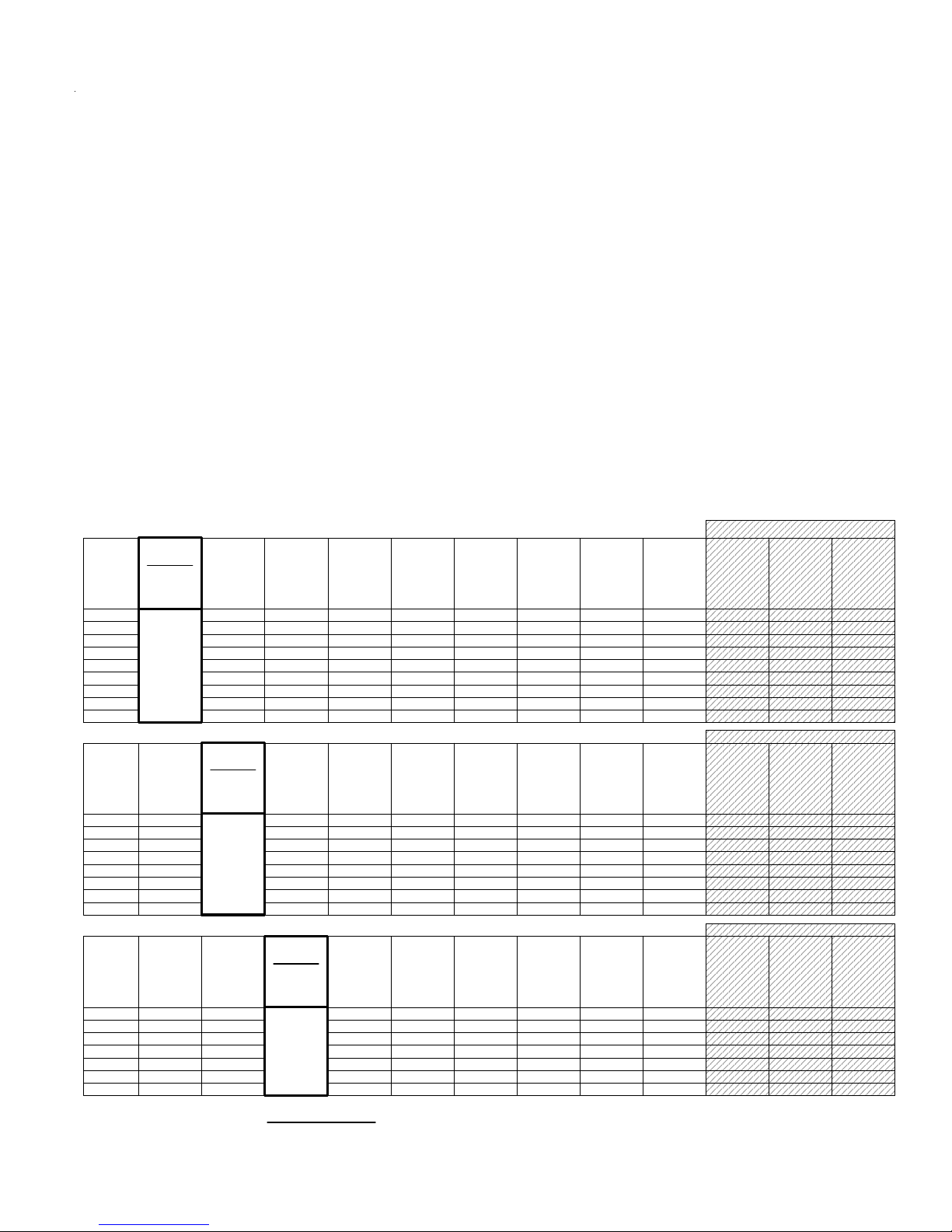
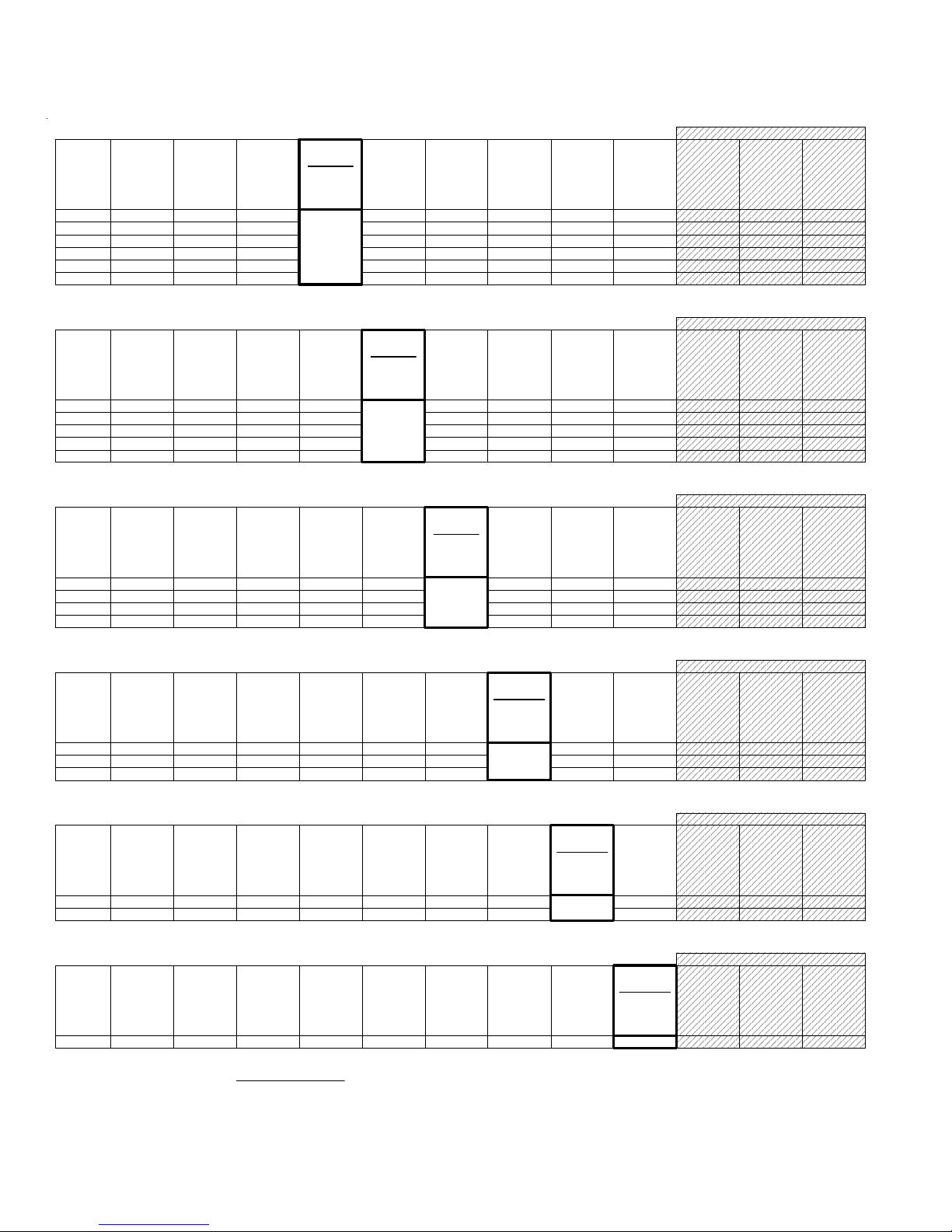
Cells marked " * * " indicate a Reserved Address which can only be used for wireless zones.
Cells marked " RRF " indicate bus addresses where ONLY a redundant M1XRF Receiver can be installed.
Cells marked " H or RRF " indicate bus addresses where either a M1XIN Hardwired Expander OR a redundant M1XRF Receiver can be installed.
These charts are intended to help visualize how the Wireless Zones and Hardwired Zones interact and to assist with setting the starting zone ID
and the data bus addresses to obtain the total and best mix of wireless and hardwired zones. Special attention should be given to the left most
column as it represents the total "max." wireless zones that may be obtained based on the starting zone ID and data bus addresses utilized by
wireless and hardwired expanders.
1. Each chart has a bolded column showing the 1st wireless zone ID at a particular value (associated with a data bus address).
NOTE: The total (max.) number of wireless zones is decreased by 16 zones for any hardwired expanders installed or
enrolled in the range of zones 17 through 160. This is because only zones 17 through 160 can be used for wireless.
2. Decide how many "total" wireless zones might be required for the job. This narrow down which charts to concentrate on.
3. Consider existing or future M1XIN hardwired zone expanders. The wireless starting zone ID is critical if you want all wireless zones to be
sequential with no hardwired zones interspersed between them. The following are some suggested guidelines:
- If the job needs 16 hardwired zones or less with no plans for expansion then start the first wireless at zone 17 (associated with data bus
address 2). This leaves the most room for future wireless expansion all the way up to zone 160.
- If the job needs lots of hardwired zones and only a handful of wireless zones consider starting the M1XRF at a higher address, leaving room
for future hardwired expansion at the lower addresses.
4. Select any chart below and start from the left column by choosing the total number of wireless zones required. Follow the row of cells across
to the bold column displaying the starting zone ID and associated data bus address where you wish to begin.
- Cells to the right marked with "* *" indicate bus addresses considered "reserved" exclusively for wireless zones. Any of these addresses may
also be used for a redundant M1XRF Receiver. Redundant Receivers provide additional range and coverage for extremely large or difficult
buildings. See Appendix C regarding Redundant Receivers.
- Cells marked "RRF" indicate bus addresses where ONLY a redundant M1XRF Receiver can be installed.
- Cells marked "H or RRF" indicate bus addresses where either a M1XIN Hardwired Expander OR a redundant M1XRF Receiver can be installed.
NOTE: An M1XRF installed for redundancy does not increase the number of wireless zones, it only increases
range and/or coverage.No RF Zones Here
No RF Zones Here
No RF Zones Here
Appendix A - Data Bus Selection Tables
Page 12 M1XRF2G Installation Manual
H or RRF
Total
Wireless
Zones
(max.)
16 H or RRF H or RRF H or RRF H or RRF H or RRFH or RRFH or RRFH or RRFH or RRF H or RRF
Data Bus
Addr 12
Zn 177-192
* * H or RRF H or RRFH or RRFH or RRFH or RRF H or RRF H or RRF
H or RRF H or RRFH or RRFH or RRFH or RRFH or RRF H or RRF
H or RRF H or RRFH or RRFH or RRFH or RRFH or RRF H or RRF
H or RRF
H or RRF
H or RRF
Data Bus
Addr 13
Zn 193-208
Data Bus
Addr 9
Zn 129-144
Data Bus
Addr 11
Zn 161-176
Data Bus
Addr 8
Zn 113-128
Data Bus
Addr 10
Zn 145-160
32
48
64
* * * *
H or RRF
* * * * * *
H or RRF
H or RRF
M1XRF
Data Bus
Addr 2
Zn 17 -32
Data Bus
Addr 3
Zn 33 - 48
Data Bus
Addr 4
Zn 49 - 64
Data Bus
Addr 5
Zn 65 - 80
Data Bus
Addr 6
Zn 81 - 96
Starting
Zn ID #97
Data Bus
Addr 7
Zn 97 - 112
H or RRF
Total
Wireless
Zones
(max.)
16 H or RRF H or RRF H or RRF H or RRFH or RRFH or RRFH or RRFH or RRFH or RRF H or RRF
Data Bus
Addr 12
Zn 177-192
* * H or RRFH or RRFH or RRFH or RRFH or RRF H or RRF H or RRF
H or RRFH or RRFH or RRFH or RRFH or RRFH or RRF H or RRF
H or RRF
H or RRF
Data Bus
Addr 13
Zn 193-208
Data Bus
Addr 9
Zn 129-144
Data Bus
Addr 11
Zn 161-176
Data Bus
Addr 10
Zn 145-160
32
48 * * * *
H or RRF H or RRF
H or RRF
M1XRF
Data Bus
Addr 2
Zn 17 -32
Data Bus
Addr 3
Zn 33 - 48
Data Bus
Addr 4
Zn 49 - 64
Data Bus
Addr 5
Zn 65 - 80
Data Bus
Addr 6
Zn 81 - 96
Data Bus
Addr 7
Zn 97 - 112
Starting
Zn ID #113
Data Bus
Addr 8
Zn 113-128
H or RRF
Total
Wireless
Zones
(max.)
16 H or RRF H or RRF H or RRFH or RRFH or RRFH or RRFH or RRFH or RRFH or RRF H or RRF
Data Bus
Addr 12
Zn 177-192
* *H or RRFH or RRFH or RRFH or RRFH or RRF H or RRF H or RRF
H or RRF
Data Bus
Addr 13
Zn 193-208
Data Bus
Addr 11
Zn 161-176
Data Bus
Addr 10
Zn 145-160
32 H or RRF H or RRF
M1XRF
Data Bus
Addr 2
Zn 17 -32
Data Bus
Addr 3
Zn 33 - 48
Data Bus
Addr 4
Zn 49 - 64
Data Bus
Addr 5
Zn 65 - 80
Data Bus
Addr 6
Zn 81 - 96
Data Bus
Addr 7
Zn 97 - 112
Data Bus
Addr 8
Zn 113-128
Starting
Zn ID #129
Data Bus
Addr 9
Zn 129-144
Total
Wireless
Zones
(max.)
16 H or RRF H or RRFH or RRFH or RRFH or RRFH or RRFH or RRFH or RRFH or RRF H or RRF
Data Bus
Addr 12
Zn 177-192
H or RRF
Data Bus
Addr 13
Zn 193-208
Data Bus
Addr 11
Zn 161-176
M1XRF
Data Bus
Addr 2
Zn 17 -32
Data Bus
Addr 3
Zn 33 - 48
Data Bus
Addr 4
Zn 49 - 64
Data Bus
Addr 5
Zn 65 - 80
Data Bus
Addr 6
Zn 81 - 96
Data Bus
Addr 7
Zn 97 - 112
Data Bus
Addr 8
Zn 113-128
Data Bus
Addr 9
Zn 129-144
Starting
Zn ID #145
Data Bus
Addr 10
Zn 145-160
H or RRF
Total
Wireless
Zones
(max.)
16 H or RRF H or RRF H or RRF H or RRF H or RRF H or RRFH or RRFH or RRFH or RRF H or RRF
Data Bus
Addr 12
Zn 177-192
* * H or RRF H or RRF H or RRFH or RRFH or RRF H or RRF H or RRF
H or RRF H or RRF H or RRFH or RRFH or RRFH or RRF H or RRF
H or RRF H or RRF H or RRFH or RRFH or RRFH or RRF H or RRF
* * * ** * H or RRF H or RRFH or RRFH or RRFH or RRF H or RRF
H or RRF
H or RRF
H or RRF
H or RRF
Data Bus
Addr 13
Zn 193-208
Data Bus
Addr 9
Zn 129-144
Data Bus
Addr 11
Zn 161-176
Data Bus
Addr 8
Zn 113-128
Data Bus
Addr 7
Zn 97 - 112
Data Bus
Addr 10
Zn 145-160
32
48
64
80
* * * *
H or RRF
* * * * * *
H or RRF
H or RRF
* *
M1XRF
Data Bus
Addr 2
Zn 17 -32
Data Bus
Addr 3
Zn 33 - 48
Data Bus
Addr 4
Zn 49 - 64
Data Bus
Addr 5
Zn 65 - 80
Starting
Zn ID #81
Data Bus
Addr 6
Zn 81 - 96
Cells marked " * * " indicate a Reserved Address which can only be used for wireless zones.
Cells marked " RRF " indicate bus addresses where ONLY a redundant M1XRF Receiver can be installed.
Cells marked " H or RRF " indicate bus addresses where either a M1XIN Hardwired Expander OR a redundant M1XRF Receiver can be installed.
H or RRF
Total
Wireless
Zones
(max.)
16 H or RRF H or RRF H or RRF H or RRF H or RRF H or RRF H or RRFH or RRFH or RRF H or RRF
Data Bus
Addr 12
Zn 177-192
* * H or RRF H or RRF H or RRFH or RRFH or RRF H or RRF H or RRF
H or RRF H or RRF H or RRF H or RRFH or RRFH or RRF H or RRF
H or RRF H or RRF H or RRF H or RRFH or RRFH or RRF H or RRF
* * * ** * H or RRF H or RRF H or RRFH or RRFH or RRF H or RRF
* ** * * * * ** * H or RRF H or RRFH or RRFH or RRF H or RRF
H or RRF
H or RRF
H or RRF
H or RRF
H or RRF
Data Bus
Addr 13
Zn 193-208
Data Bus
Addr 9
Zn 129-144
Data Bus
Addr 11
Zn 161-176
Data Bus
Addr 8
Zn 113-128
Data Bus
Addr 6
Zn 81 - 96
Data Bus
Addr 7
Zn 97 - 112
Data Bus
Addr 10
Zn 145-160
32
48
64
80
96
* * * *
H or RRF
* * * * * *
H or RRF
H or RRF
* *
M1XRF
Data Bus
Addr 2
Zn 17 -32
Data Bus
Addr 3
Zn 33 - 48
Data Bus
Addr 4
Zn 49 - 64
Starting
Zn ID #65
Data Bus
Addr 5
Zn 65 - 80
No RF Zones Here
No RF Zones Here
No RF Zones Here
No RF Zones Here
No RF Zones Here
No RF Zones Here
Appendix A - Data Bus Selection Tables (cont'd)

M1XRF2G Installation Manual Page 13
Example A
All 208 Zones as Hardwired
Zones
1-16
Inputs on
Main Panel
Zones
17-32 M1XIN
Zones
33-48
Zones
49-64
Zones
65-80
Zones
81-96
Zones
97-112
Zones
113-128
Zones
129-144
Zones
145-160
Zones
161-176
Zones
177-192
Zones
193-208
Example B
16 Hardwired Zones
144 Wireless Zones
NO
M1XIN
Expanders
on these
addresses
Example C
48 Hardwired Zones
112 Wireless Zones
PLUS 2 Redundant Receivers
Bus
Addr x
Bus
Addr 2
M1XIN
Bus
Addr 3
M1XIN
Bus
Addr 4
M1XIN
Bus
Addr 5
M1XIN
Bus
Addr 6
M1XIN
Bus
Addr 7
M1XIN
Bus
Addr 8
M1XIN
Bus
Addr 9
M1XIN
Bus
Addr 10
M1XIN
Bus
Addr 11
M1XIN
Bus
Addr 12
M1XIN or
Keypad
Zones
Bus
Addr 13
Zones
1-16
Inputs on
Main Panel
Zones
17-32
Zones
33-48
Zones
49-64
Zones
65-80
Zones
81-96
Zones
97-112
Zones
113-128
Zones
129-144
Zones
145-160
Zones
161-176
Zones
177-192
Zones
193-208
Bus
Addr x
Bus
Addr 2
Bus
Addr 3
Bus
Addr 4
Bus
Addr 5
Bus
Addr 6
Bus
Addr 7
Bus
Addr 8
Bus
Addr 9
Bus
Addr 10
M1XIN or
Keypad
Zones
Bus
Addr 13
M1XRF
M1XIN or
Redundant
M1XRF *
NO
M1XIN
Expanders
on these
addresses
Zones
1-16
Inputs on
Main Panel
Zones
17-32
Zones
33-48
Zones
49-64
Zones
65-80
Zones
81-96
Zones
97-112
Zones
113-128
Zones
129-144
Zones
145-160
Zones
161-176
Zones
177-192
Zones
193-208
Bus
Addr x
Bus
Addr 2
Bus
Addr 3
Bus
Addr 4
Bus
Addr 5
Bus
Addr 6
Bus
Addr 7
Bus
Addr 8
Bus
Addr 9
Bus
Addr 10
M1XIN or
Keypad
Zones
Bus
Addr 13
M1XRF
M1XIN
M1XIN
Bus
Addr 14
Bus
Addr 15
N/A
N/A
N/A
N/A
Bus
Addr 14
Bus
Addr 15
N/A
N/A
Bus
Addr 14
Bus
Addr 15
N/A
N/A
Maximum of 112 Wireless Zones
< ------- Redundant M1XRF *
< ------- Redundant M1XRF *
Maximum of 144 Wireless Zones
N/A
N/A
N/A
N/A
M1XIN or
Redundant
M1XRF *
Bus
Addr 11
Bus
Addr 12
Bus
Addr 11
Bus
Addr 12
Appendix B - Examples of Zone Configurations

Page 14 M1XRF2G Installation Manual
After the first M1XRF2G Receiver has been installed, additional receivers can be installed for redundancy or improved coverage
and range. Each addtional receiver will need its own data bus address and will need to be enrolled into the control. The data
bus address setting of any additional "redundant" Receivers can be any unused data bus address except for addresses 13, 14,
15, 16.
NOTE: While M1XIN Expanders cannot be assigned to addresses overlapped by wireless zones this is not true for M1XRF2G
Receivers. From the example above, addresses 3, 4, and 5 could be used by additional "redundant" Receivers. In theory it
is possible to install up to 11 total M1XRF2G Receivers onto a single M1 or M1EZ8 control, but only if there were NO M1XIN
Expanders installed.
* For large installations or added coverage in areas with poor wireless conditions, additional M1XRF "Redundant" Receivers can be connected to
the data bus. Redundant receivers must be addressed and enrolled for proper supervision. Loss of any enrolled bus device causes a Missing Bus
Device Trouble. NOTE: Redundant M1XRFs can be set to any of the unused addresses that fall in the total wireless zone number assignments.
Offices
Shipping M1XRF2G
M1XRF2G M1XRF2G
Warehouse Production Sales
EXAMPLE OF LARGE COMMERCIAL BUILDING with 3 M1XRF2G Receivers
Appendix C - Installing Multiple Redundant Receivers

M1XRF2G Installation Manual Page 15
Appendix D - Updating Firmware in the ELK-M1XRF2G
Operating firmware is stored in “Flash” memory. This state-of-the-art memory allows electronic field updates and eliminates
the old fashion method of changing IC chips or shipping boards back to the factory. As new firmware updates become avail-
able, they will be posted on ELK’s Dealer ONLY restricted website found at www.elkproducts.com. NOTE: Firmware updating
can only be done through the M1 Control using a Direct to PC Com port connection or an optional Ethernet Network connec-
tion. Dial-up connections cannot be used to perform firmware updates.
How to Update Firmware:
1. Physically connect the Computer and Control using either the RS-232 Serial Ports or the M1XEP Ethernet Interface.
3. Start ElkRP and open the account belonging to the control. Click on the Connection menu icon and establish a connection.
Again, use the appropriate Direct using Com_ OR Network options.
4. Click on Update/Verify Firmware from the Send/Rcv menu icon.
5. On the Update/Verify screen, select the device to be updated. In this case it is a Input Expander. Then also select the
“Update to new firmware” option. Then click Continue.
6. The Update Firmware screen displays the device name, the current Firmware, Hardware, and Bootware version, and a pull
down window for selecting the firmware version to use on the update. Select the appropriate firmware that you wish to use.
NOTE: All update (.bin) files that are downloaded or received should be stored in your ~Program Files\ElkRP\Updates
directory. This is where RP looks for all update files.
7. Click on the check box for “Update”. If “Reprogram” or “Rollback” is displayed the firmware file is the same as OR older that
what is in the control. Reprogramming with the same firmware is a waste of time but was included for factory testing
purposes. Rollback is not recommended except under the guidance of Elk Technical Support.

Page 16 M1XRF2G Installation Manual
Table of contents
Other Elk Receiver manuals


