Eltek Valere PSS30 User manual

Rectifier
PSS30
USER MANUAL
UM_PSS30_E_R00

Primary Switch Mode Rectifier
PSS30
User manual
Page 2 (28)
Eltek Valere Industrial ©2008 UM_PSS30_E_R00
Notes to this manual
ATTENTION! Read this manual before installing and commissioning the specified module.
This manual is a part of the delivered module. Familiarity with the contents of this manual is required
for installing and operating the specified module.
The function description in this manual corresponds to the stage of technology at the date of
publishing. Technical changes and changes in form and content can be made at any time by the
manufacturer without notice. There are no obligations to update the manual continually.
The rules for prevention of accidents for the specific country and the general safety rules in
accordance with IEC 364 must be observed.
The module is manufactured in accordance with applicable DIN and VDE standards such as VDE 0106
(part 100) and VDE 0100 (part 410). The CE marking on the module confirms compliance with EU
standards 73/23 EWG (low voltage) and 89/339 EWG (electromagnetic compatibility) if the installation
and operation instructions are followed.
Supplier:
ELTEK VALERE INDUSTRIAL GmbH
Schillerstraße 16
D-32052 Herford
+ 49 (0) 5221 1708-210
FAX + 49 (0) 5221 1708-222
Email [email protected]
Internet http://www.eltekvalere-industrial.com
©Copyright ELTEK VALERE INDUSTRIAL 2008. All rights reserved.
NOTE: Repetition, copying and /or taking possession of this user manual, even in extracts, with
electronic or mechanical means, requires the written prior permission of the manufacturer.
Primary Switch Mode Rectifier
PSS30
User manual
Page 3 (28)
Eltek Valere Industrial ©2008 UM_PSS30_E_R00
The current revision status of this manual is the following:
Revision: 00
Date: 2008-10-06
Revision Description of change Writer Date
00
EVI layout and additional pictures inserted, minor text modi-
fications (based on the original version
“PSS30_E1_20071023.doc”)
RTH 2008-10-06

Primary Switch Mode Rectifier
PSS30
User manual
Page 4 (28)
Eltek Valere Industrial ©2008 UM_PSS30_E_R00
Table of Contents
Safety instructions and waste disposal rules .................................................................. 2
1. General ................................................................................................................................... 2
2. Type range............................................................................................................................. 2
2.1 Available options and accessories:....................................................................................................... 2
3. Start up procedure.............................................................................................................. 2
4. Operation ............................................................................................................................... 2
5. Functions ............................................................................................................................... 2
5.1. Circuit diagram........................................................................................................................................... 2
5.2 Electrical function description ............................................................................................................... 2
5.2.1 Electrical insulation........................................................................................................................ 2
5.2.2 Input................................................................................................................................................... 2
5.2.3 Output............................................................................................................................................... 2
5.2.4 Dynamic regulation of the output voltage .............................................................................. 2
5.2.5 RFI suppression ............................................................................................................................... 2
5.2.6 CAN-Bus interface.......................................................................................................................... 2
5.3 Monitoring.................................................................................................................................................... 2
5.3.1 Mains voltage monitoring............................................................................................................. 2
5.3.2 Operation monitoring .................................................................................................................... 2
5.3.3 Monitoring „Boost charge“ ........................................................................................................... 2
5.3.4 Monitoring „Constant current operation“................................................................................ 2
5.3.5 Output voltage low........................................................................................................................ 2
5.3.6 Output voltage high....................................................................................................................... 2
5.3.7 Protection against overheating/collective failure ................................................................ 2
5.3.8 Signals............................................................................................................................................... 2
5.4 Output and threshold adjustment......................................................................................................... 2
6. External Functions............................................................................................................... 2
6.1 Output voltage sensor leads .................................................................................................................. 2
6.2 Temperature compensation of the charging voltage...................................................................... 2
6.3 External switch ON/OFF function.......................................................................................................... 2
6.4 Discharge test ............................................................................................................................................ 2
6.5 Boost charge mode ................................................................................................................................... 2
7. Operation elements and connectors.............................................................................. 2
7.1 Front view/Operation elements 24/48/60/108V version ............................................................. 2
7.2 Front view/Operation elements 216V version................................................................................... 2
7.3 Electrical connectors................................................................................................................................ 2
8. Maintenance ......................................................................................................................... 2
9. Trouble shooting.................................................................................................................. 2
9.1. No output voltage .................................................................................................................................... 2
9.2. Deviation of the output voltage ........................................................................................................... 2
10. Technical data.................................................................................................................... 2
10.1. General technical data.......................................................................................................................... 2
10.2. Specific data (depending on the type).............................................................................................. 2
10.3. Dimensional drawings, PSS30 (24, 48, 60 and 108V version)..................................................... 2
10.4. Dimensional drawings, PSS30 (216V version)................................................................................. 2

Primary Switch Mode Rectifier
PSS30
User manual
Page 5 (28)
Eltek Valere Industrial ©2008 UM_PSS30_E_R00
Safety instructions and waste disposal rules
Warning!
Because several components of operating electrical modules are charged by dangerous voltage, the
improper handling of electrical modules may be the cause of accidents involving electrocution, injury,
or material damages.
•Operation and maintenance of electrical modules must be performed by qualified skilled
personnel such as electricians in accordance with EN 50110-1 or IEC 60950.
•Install the module only in areas with limited access to unskilled personnel.
•Before starting work, the electrical module must be disconnected from mains. Make sure that
the module is earthed.
•Do not touch connector pins as they can be charged with dangerous voltage up to 30 seconds
after disconnection.
•Only spare parts approved by the manufacturer must be used.
All electric modules must be disposed of separate from domestic waste at collecting points that
have been set up by the government or municipal authority.
“Separate collection is the precondition to ensure specific treatment and recycling of WEEE and is
necessary to achieve the chosen level of protection of human health and the environment in the
Community.”
The above statement from EU directive 2002/96/EC applies to all electric modules installed within
EU countries.
In countries outside the EU, different rules may apply regarding waste disposal of electric modules.
For more information about waste disposal of your discarded equipment, contact your
ELTEK VALERE INDUSTRIAL partner.

Primary Switch Mode Rectifier
PSS30
User manual
Page 6 (28)
Eltek Valere Industrial ©2008 UM_PSS30_E_R00
1. General
The primary switched mode rectifier type PSS30 (named PSS in the following) delivers an output
power to a maximum of 3.0kW.
Typical applications are DC power supplies, uninterruptable power supplies with parallel connected
batteries. Rectifiers of type PSS have good dynamic regulation properties at input voltage changes
and load variations.
It works with an IV line according to DIN 41772 and is a connection unit, ready for integration in system
cabinets with 19“ standard frame according to DIN 41494. The operation elements, measurement in-
struments and input/output connectors are fitted on the front panel of the module.
Parallel operation of several modules is possible (with or without decoupling diodes at the output side).
In this case the modules operate with decreased line or in current sharing mode (adjustable at factory).
In the current sharing mode the variations of the output currents of the modules are ≤ ±5 % of the
nominal output current.
An internal active decoupling circuit is available as option.
PSS modules also operate single side grounded or ungrounded at input and output.
2. Type range
Type
designation
Material
code
Input voltage
(VAC)
Output voltage
(VDC)
Output current
(ADC)
PSS30/24-80-CAN 100-030-140.00 230 24 80
PSS30/48-50-CAN 100-030-150.00 230 48 50
PSS30/60-40-CAN 100-030-160.00 230 60 40
PSS30/108-22,3-CAN 100-030-170.00 230 108 22,3
PSS30/216-11,1-CAN 100-030-180.00 230 216 11,1
PSS30/216-11,1-
Relay
100-030-180.01 230 216 11,1
Primary Switch Mode Rectifier
PSS30
User manual
Page 7 (28)
Eltek Valere Industrial ©2008 UM_PSS30_E_R00
2.1 Available options and accessories:
Article Material code
Connector set for input/output <40A 880-100-STK.01
Connector set for input/output >40A 880-100-STK.02
Connector set for input/output, PSS 216V 880-100-STK.03
Temperature sensor (LM335) integrated in a terminal end M5,
with 4m connection wire
880-300-TMP.01
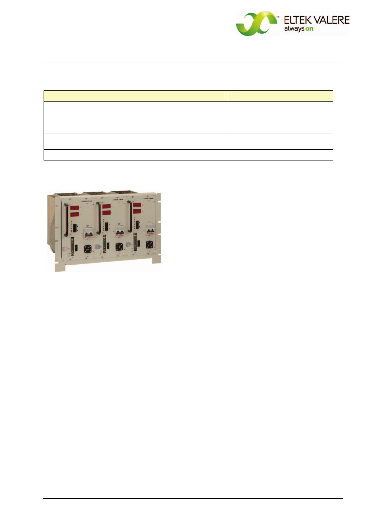
19“ sub rack, 7U 880-MEC-BGT7.00
Photo: 19“ sub rack, 7U, for the integration of three rectifiers PSS

Primary Switch Mode Rectifier
PSS30
User manual
Page 8 (28)
Eltek Valere Industrial ©2008 UM_PSS30_E_R00
3. Start up procedure
Before connecting to the input voltage, it should be checked that the voltage information on the type
plate corresponds to the available voltage and also that the polarity corresponds to the connection
plan of the plug. The mains connection is done via a plug at the front side. The protective conductor
should be generally connected (protection class 1, leakage current ≤3.5mA).
Important:
If one pole is grounded at the output side, the module has to be connected with an additional non-fused
earthed conductor wire on the earth screw (left side on front panel). In this case the PE wire should not
be connected to the input connector to prevent earth circuit. This is very important for paralleled mod-
ules without decoupling diodes at the output side.
The DC output and signal contacts are to be connected with a SUB-MIN-D-connector, type 21WA4. For
modules with an output current >40A two heavy-duty contacts are paralleled. In this case it is impor-
tant that both contacts are symmetrically loaded. The current must be ≤40A per each contact. The
signalling contacts for monitoring, sense links and active current sharing mode are also included in the
output connector.
The rectifier has big capacitors at the output. If you connect a switched off module to a battery or
other modules which operates in parallel, a high capacitor charge current will occur. This current can
destroy the contacts on the output connector.
You can avoid this effect considering the following rules:
•Switch on the PSS module before connecting the output plug
•Disconnect the DC bus by switch or fuse
•Charge the capacitors with resistor (approx. 1 Ohm/V)
•Use decoupling diodes at the output side
After switching off, the capacitors are still fully charged. The discharge time is approx. 4s for the input
and approx. 15s for the output side.
The rectifier is forced-cooled with fan. The ambient temperature has to be lower than 45 °C. If more
than one subrack mounting level is used in one cabinet there must be a difference between two
mounting levels of 3U (approx. 130mm) for an unobstructed airflow. The temperature within the cabi-
net should not be higher than 40 °C.
If there is a higher temperature the life time of the modules will be decreased.
The internal losses per module are approx. 260 up to 290W (depending on the type).
4. Operation
All operation elements are fitted on the front panel of the module. The function of each individual
operation element is described on the following pages.
See also section 7. “Operation elements and connectors”.

Primary Switch Mode Rectifier
PSS30
User manual
Page 9 (28)
Eltek Valere Industrial ©2008 UM_PSS30_E_R00
5. Functions
5.1. Circuit diagram
Picture:
Schematic Block
Diagram PSS30

Primary Switch Mode Rectifier
PSS30
User manual
Page 10 (28)
Eltek Valere Industrial ©2008 UM_PSS30_E_R00
5.2 Electrical function description
Rectifiers of type PSS consist of following main parts:
1. Line filter to reduce the high-frequency transients produced by the device as well as damping
the transients and noise voltage which are superimposed on the mains.
2. Mains rectifier with switched step-up-converter (operation frequency 100 kHz) to transform the
input voltage in a pre-regulated DC voltage of approx. 380V and to control the waveform of the
input current (sinusoidal!) as well as to control the power factor (>0.99). An additional function
is the limitation of inrush current.
3. Transistor bridge to transform the 380VDC to a pulse width modulated AC voltage with a fre-
quency of 100KHz.
4. HF transformer for the decoupling of the primary and secondary side and adaptation of the volt-
age level to the secondary side.
5. Rectifier diodes
6. LC filter to reduce the voltage ripple at rectifier output.
7. Output filter for RFI suppression and to reduce the noise level on DC line.
8. Internal power supply to supply the primary and secondary control units with potential separa-
tion.
9. Controlled system, opto-decoupled.
10. Adjustment panel for adjustment of output parameters, signals and measurement instruments.
5.2.1 Electrical insulation
Due to the construction principle of the module (module parts) and separated wiring of mains input and
DC output, the PSS meets the following standards:
•Devices with Vo ≤60VDC protection against dangerous body currents through low voltage with
safe electrical decoupling according to EN 60950 and VDE 0100.
•Devices with Vo > 60VDC saved electrical decoupling to Vo = 220VDC according to EN 60950 and
VDE 0160.
5.2.2 Input
The input is protected with a 2-pole circuit breaker. This circuit breaker is also used as on/off-switch.
The MCB is -seen from the mains input side- connected ahead of the input filter. An additional internal
fuse is used to protect the controller.
The rectifier has a current limitation which limits the inrush current to the level of the nominal input
current.
5.2.3 Output
The output line is an IV-line according to DIN 41772 /DIN 41773. Active current sharing mode or de-
creased charge line (-1% at 100% Inom) is possible. Serially the decreased charge line is factory preset.
The output is continuous short circuit proof (constant current controlling).
It is possible to use three different output voltages:
1. Voltage for trickle charge
2. Boost charge
3. Battery test
The output voltage for trickle charge is standard set.
For the use of “Boost charge” or “Battery test”, the pins of the signal connectors are to be connected
as described in section 7.3 “Electrical connectors”.

Primary Switch Mode Rectifier
PSS30
User manual
Page 11 (28)
Eltek Valere Industrial ©2008 UM_PSS30_E_R00
5.2.4 Dynamic regulation of the output voltage
At load jumps between 10 % and 90 % Inom / 90 % and 10 % Inom the dynamic voltage difference is max.
± 3 % and is corrected in max. 1,5 ms to static levels.
5.2.5 RFI suppression
Modules of type PSS meet the standard VDE 0878 T1 and EN 55011/55022 class ‘B’. The output ripple
is (psophometrically measured according to CCITT) < 1mV (24V), < 1,8mV (48V) and <2mV (60V).
5.2.6 CAN-Bus interface
The rectifier PSS is equipped with a serial CAN-Bus interface. Two CAN connectors (RJ11, 6-pole) are
fitted at the front side of the 24V - 110V version. For the 220V version the CAN-Bus connection is inte-
grated in the front side connector X4.
Several modules in a system or parallel connection can be controlled and monitored through the CAN-
Bus by a central DC controller unit MU1000C.
The following parameters of a specific rectifier unit can be controlled or monitored:
•Output voltage
•Output current
•Module status
Furthermore, the rectifier unit receives all threshold values through the CAN-Bus from the
DC controller unit.
REMARK: If several paralleled rectifiers are controlled by a central DC controller unit, it is important to
assign an explicit CAN-Bus address to each individual rectifier (see section 5.4).
5.3 Monitoring
5.3.1 Mains voltage monitoring
Mains voltage monitoring; signalling with LED "Switch symbol", criterion: output voltage of step-up-
converter ≥370 V, at the same time operation monitoring of step-up-converter (equivalent to main
voltage of approx. ≥195 VAC; depends on the load).
The LED is dark if the mains voltage is low or the step-up-converter is out of order.
This signal is included in the collective failure signal of the rectifier. Additional there is an optocoupler
signal (mains O.K.).
For high input voltages (approx. >270VAC) there is implied an automatic switch off function.

Primary Switch Mode Rectifier
PSS30
User manual
Page 12 (28)
Eltek Valere Industrial ©2008 UM_PSS30_E_R00
5.3.2 Operation monitoring
Functional monitoring; signalling with LED "VO1", criterion: output voltage ≥97 % of adjusted output
voltage without constant current regulation; ≥85 % of adjusted output voltage with constant current
regulation. The signalling threshold of this monitoring automatically follows the adjusted nominal out-
put voltage.
This signal is included in the collective failure signal of the rectifier. Additional there is an optocoupler
signal (Vo O.K.) available.
At operation with internal decoupling diodes the voltage is measured ahead of the diodes.
5.3.3 Monitoring „Boost charge“
If „boost charge“ is activated (see section 6.5), LED V02 is ON, LED V01 is OFF.
5.3.4 Monitoring „Constant current operation“
Constant current operation (output current limiting active) is signalled with a yellow LED I0.
5.3.5 Output voltage low
Output voltage low monitoring; signalling with LED "V<", criterion: Output voltage is higher than ad-
justed level V<; this signal is included in the collective failure signal of the rectifier.
This signal has its own relay contact on the signalling connector. If the voltage value is O.K., pin 13 and
pin 17 of X2 are closed.
5.3.6 Output voltage high
Output voltage high monitoring; signalling with LED "V>", criterion: output voltage higher than adjusted
level V>;
This signal is included in the collective failure signal of the rectifier. If there is an error, the LED is ON
and the rectifier internally switches off. You have to reset the unit by ON/OFF switch.
5.3.7 Protection against overheating/collective failure
A collective failure is signalled with the LED “Bell symbol”. Furthermore overheating is signalled;
criterion: Temperature of the heat sink > 90°C (the unit switches OFF). This signal is included in the
collective failure signal. You have to reset the unit by ON/OFF switch.

Primary Switch Mode Rectifier
PSS30
User manual
Page 13 (28)
Eltek Valere Industrial ©2008 UM_PSS30_E_R00
5.3.8 Signals
The following signals are available as potential-free optocoupler signals:
1. "Vo O.K.",
2. "Mains O.K."
3. Constant current mode “Iconst"
The maximum contact load is 30V/5mA.
The optocouplers switch OFF at signal 1. and 2., they switch ON at signal 3.
The collective failure signal is delayed for approx. 10s and is available (as well as the signal V>) via a
potential-free relay contact. If a failure exists, the relay switches OFF.
For PSS30, 24/48/60/110V version:
The relay contacts between pin 14 and pin 15 of X2 are open and between pin 15 and pin 16 are closed
at failure.
For PSS30, 220V, only relay version:
The relay contacts between pin 12 and pin 13 of X4 are open and between pin 13 and pin 14 are
closed at failure.
The following monitoring items are included in the collective failure signal:
1. Mains voltage monitoring
2. Operation monitoring
3. Output voltage low
4. Output voltage high
5. Over temperature
5.4 Output and threshold adjustment
The adjustment of output values and monitoring thresholds are very easy. All values are to be adjusted
with front keys; the actual values are indicated with the front side digital displays.
In normal operation the top display shows the output voltage (VO1, VO2 or VO3 depending on the se-
lected operation mode) and the bottom display shows the output current (Io).
In the adjustment mode, the top display shows the name of the parameter, the bottom display shows
the related value.
For any adjustment please follow these instructions:
•press both keys UP/DOWN (↑↓) together for a short time; the rectifier changes to adjustment
mode
•press the key UP (↑) or DOWN (↓) to change the adjustment parameter (see the following table)
•press both keys UP/DOWN (↑↓) together for a short time; the rectifier changes to value change
mode
•press the key UP (↑) or DOWN (↓) to change the adjustment value (if you hold the key the value
changes quicker)
•press both keys UP/DOWN (↑↓) together for a short time; the rectifier changes back to adjustment
mode (at this moment the changed value will be stored)
•press both keys UP/DOWN (↑↓) for approx. 3s. to change to the operation mode
You can leave the adjustment mode at any time with pressing the keys UP/DOWN (↑↓) for approx. 3s.
Primary Switch Mode Rectifier
PSS30
User manual
Page 14 (28)
Eltek Valere Industrial ©2008 UM_PSS30_E_R00
Adjustable parameters in the adjustment mode:
Displayed short term
of the parameters
Parameter meaning
VO1 trickle charge voltage
VO2 boost charge voltage (see section 6.5)
VO3 voltage at discharge test (see section 6.4)
Io output current
V< output voltage low threshold (see section 5.3.5)
V> output voltage high threshold (see section 5.3.6)
t temperature coefficient for temperature compensation of the charge
voltage (see section 6.2)
Adr change CAN-Bus address
The threshold values for mains/step-up-converter and over heating are not changeable.
The threshold values of DC voltage low (V<) and DC voltage high (V>) can be individually set within a
limited adjustment range.
For more information regarding the adjustment ranges and factory preset values see section
10. “Technical data”.
6. External Functions
6.1 Output voltage sensor leads
Voltage losses at wires or diodes are to be compensated with sense links for the output voltage.
The maximum regulation difference is approx. 4 % of the nominal voltage.
Cable break at sense links, confusing of poles or short circuit can not damage the rectifier. At cable
break of the sense link, a voltage increase of max. 4% is possible.
6.2 Temperature compensation of the charging voltage
For the use of closed batteries we recommend temperature-controlled compensation of the charge
voltage.
Connect an external active temperature sensor (option) to the signalling connector. The standard set
temperature coefficient is -4mV/K per cell (for a temperature range of 0-50 °C). The basic temperature
is 20°C. The coefficient can be adjusted between 0 to -6mV/K per cell (see section 5.4).
Connect the sensor with a 2-pole wire (0,25mm2). It can be directly mounted on top of the battery or on
battery poles. At great distances (approx. 2m) we recommend the use of a shielded wire with connec-
tion of the shield to rectifiers ground.
6.3 External switch ON/OFF function
The rectifier can be externally switched on/off with applying an external DC voltage over an external
switch to the respective pins according to section 7.3. The output of the PSS rectifier switches OFF, if
the external voltage is applied. In this case, the switch-off does not result in a collective failure signal!
The input is potential free due to the use of an optocoupler and meets the supposition for safe electri-
cal decoupling to mains and output side. The signalling voltage is 10-24V, the internal resistance is
2,7kOhm. The input is protected against reversed polarity. At higher supply voltages the current in the
control circuit has to be limited to approx. 5-7mA with a series resistor (e. g. 6,8kOhm at 48/60VDC).

Primary Switch Mode Rectifier
PSS30
User manual
Page 15 (28)
Eltek Valere Industrial ©2008 UM_PSS30_E_R00
6.4 Discharge test
It is possible to test the capacity of a battery which operates in parallel with the rectifier.
To select the discharge test mode you have to connect –Vo to pin 2 of the output connector X2 (see
section 7.3).
The discharge test voltage can be adjusted by the user (parameter VO3; see section 5.4).
If the discharge test mode is active, the LED VO1 is ON; LED VO2 is OFF.
6.5 Boost charge mode
The rectifier module has a second charge line (boost charge line). To select this mode you have to
connect +Vo to pin 2 of the output connector X2 (see section 7.3). The boost charge mode is
signalized by LED VO2. The voltage value can be adjusted by the user (see section 5.4).
NOTE: For 60/108/216V units: For the connection to +VOan additional series resistor is to be used
(60 V: 18kOhm; 108 V: 56kOhm; 216V: 150kOhm).

Primary Switch Mode Rectifier
PSS30
User manual
Page 16 (28)
Eltek Valere Industrial ©2008 UM_PSS30_E_R00
7. Operation elements and connectors
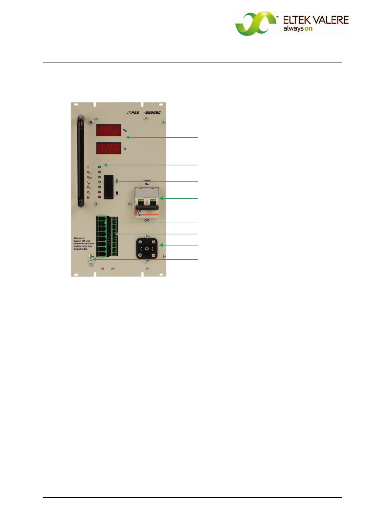
7.1 Front view/Operation elements 24/48/60/108V version
Digital display for output voltage and -current/
indication of the parameters and related values in
the adjustment mode
LED indicators
Adjustment keys „UP“ and „DOWN“
Input-side fuse; ON-/OFF switch
Locking slide for the DC connector
DC connector X2 (& signals)
Two CAN-Bus connectors (RJ11, 6-pole)
Mains connector X1
PE connector (M4 bolt)
Primary Switch Mode Rectifier
PSS30
User manual
Page 17 (28)
Eltek Valere Industrial ©2008 UM_PSS30_E_R00
7.2 Front view/Operation elements 216V version
Digital display for output voltage and -current/
indication of the parameters and related values in
the adjustment mode
LED indications
Adjustment keys „UP“ and „DOWN“
Input-side fuse; ON-/OFF switch
DC connectors X2
Signals/CAN-Bus connectors X4
Mains connector X1
PE connector (M4 bolt)
Primary Switch Mode Rectifier
PSS30
User manual
Page 18 (28)
Eltek Valere Industrial ©2008 UM_PSS30_E_R00
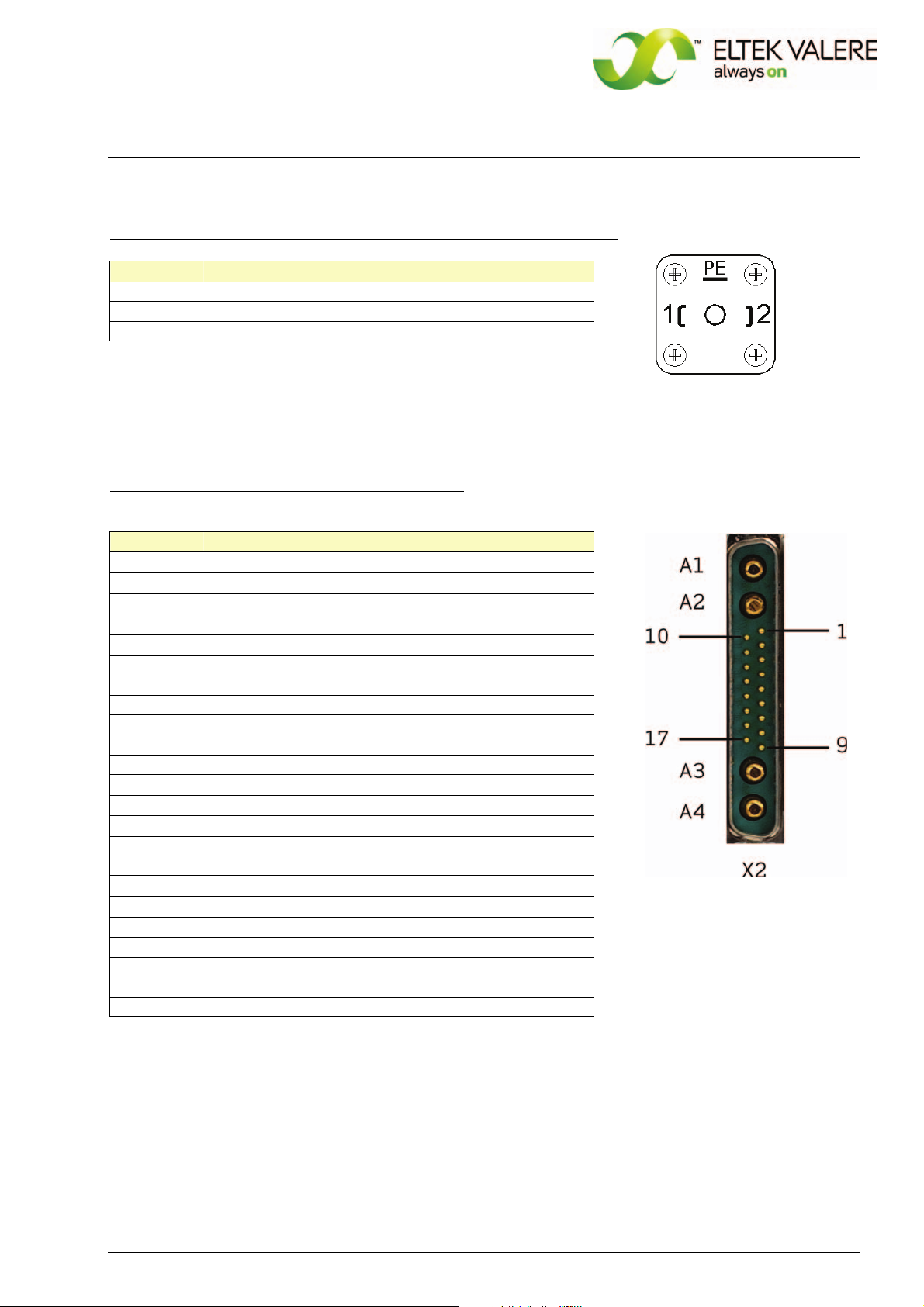
7.3 Electrical connectors
AC-mains input (GDM-connector) for all PSS30 versions (connector X1)
X1, pin Function
1 L1 - Input
2 N - Input
PE PE
X1
DC output and signalling contacts (SUB-MIN-D-connector 21WA4),
for 24, 48, 60 and 108V versions (connector X2):
X2, pin Function
A1 (+) - output
A2 (+) - output (additional for Io ≥40A)
A3 (-) - output (additional for Io ≥40A)
A4 (-) - output
1 (+) - output voltage sense link
2 signal input discharge test mode / boost charge
mode
1
)
3 optocoupler emitter
4 optocoupler collector "Mains O.K."
5 optocoupler collector "Vo O.K."
6 optocoupler collector "Io"
7 temperature sensor (+)
2
)
8 control wire for active current sharing
3
)
9 (-) - output voltage sense link
10 analogue ground (for temperature sensor (-), active
current sharing)
11 (+) external switch on/off
4
)
12 (-) external switch on/off
13 relay contact V< , N/O
5
)
14 relay contact collective failure , N/O
15 relay contact collective failure , COM
16 relay contact collective failure , N/C
17 relay contact V< , COM
REMARK: The legend of the items
1)
…
5)
follows on the next page.

Primary Switch Mode Rectifier
PSS30
User manual
Page 19 (28)
Eltek Valere Industrial ©2008 UM_PSS30_E_R00
1)
Tri-state-input, pin 2 at -VO= discharge test mode; pin 2 at +VO= boost charge mode
NOTE: For 60/108/216V units: For the connection to +VOan additional series resistor is to be used
(60 V: 18kOhm; 108 V: 56kOhm; 216V: 150kOhm).
2)
Connection of temperature sensor with 2-pole wire to pin 7(+) and pin 10 (-)
NOTE: If several modules are paralleled, pin 7 of each individual unit and pin 10 of each individual unit
has to be connected.
3)
At active current sharing mode of paralleled units the pin 8 of each individual module has to be con-
nected.
4)
External switch on/off with optocoupler: internal series resistor 2,7kOhm, Imin< = 5mA, Imax = 10mA
(see section 6.3).
NOTE: The input is potential free with safe electrical decoupling to primary side and with 500VDC to
secondary side.
5)
The relay outputs are potential free with safe electrical decoupling to primary side and with 500VDC
to secondary side.
ATTENTION! If decoupling diodes are output-side integrated in minus, the use of sense links are not
allowed.
For the 216V version, the DC output and signal connectors are separated.
DC output (8xCOMBICON 4mm2)
for 216V version (connector X2):
X2, pin Function
1 (+) - output
2 (+) - output
3 (+) - voltage sense link
4 control wire for active current sharing
6
)
5 BUS ground
6 (-) - voltage sense link
7 (-) - output
8 (-) - output

Primary Switch Mode Rectifier
PSS30
User manual
Page 20 (28)
Eltek Valere Industrial ©2008 UM_PSS30_E_R00
Signals (connector X4 = 15 x COMBICON 1,5mm2):
Pin assignment of X4 for PSS30/216V with signalling relay (without CAN-Bus)
Pin assignment of X4 for
PSS30/216V with CAN-Bus
(without signalling relay)
REMARK: The legend of the items
1)
…
6)
follows on the next page.
X4, pin Function
1 (+) external switch on/off
4
)
2 (-) external switch on/off
3 optocoupler emitter
4 optocoupler collector "Mains O.K."
5 optocoupler collector "VO O.K."
6 optocoupler collector "IO"
7 BUS ground
8 signal input discharge test mode / boost charge mode
1
)
9 temperature sensor (+)
2
)
10 control wire for current sharing mode
3
)
11 relay contact V< , NO
5
)
12 relay contact collective failure , NO
5
)
13 relay contact collective failure , COM
14 relay contact collective failure , NC
5
)
15 relay contact V< , COM
X4, pin Function
1 (+) external switch on/off
4
)
2 (-) external switch on/off
3 optocoupler emitter
4 optocoupler collector "Mains O.K."
5 optocoupler collector "VO O.K."
6 optocoupler collector "IO"
7 BUS – GND
8 signal input discharge test mode / boost charge mode
1
)
9 temperature sensor (+)
2
)
10 control wire for current sharing mode
3
)
11 CVCC +
12 CAN-H
13 CAN-L
14 CVSS -
15 Not connected
This manual suits for next models
12
Table of contents
Popular Industrial Electrical manuals by other brands

Murata
Murata GQM22M5C2H1R1BB01 Series Reference sheet

Murata
Murata GJM0335C1E3R6CB01 Series Reference sheet

Murata
Murata GQM1885C1H180GB01 Series Reference sheet

Greenheck
Greenheck AMD-42-TD Installation, operation and maintenance manual

Murata
Murata GRM188C71A475ME11 Series Reference sheet

PSI
PSI Generator Tap Box instruction manual


Murata
Murata GRM0335C1E470JA01 Series Reference sheet

Siemens
Siemens 8PQ9800-0AA55 operating instructions

Murata
Murata GRM21BR71E475KA73 Series Reference sheet

Murata
Murata GRM188R71C273KA01 Series Reference sheet

Murata
Murata GRM0225C1C120GA03 Series Reference sheet

Murata
Murata GRM21BR61C106ME15 Series Reference sheet