EMB Downdraft User manual

for EMB
DOWNDRAFT
EXTRACTOR HOOD
as of 08.2016
Assembly and operating instructions

Table of contents:
Safety information Page 1
Before using for the first time Page 1
Equipment Page 1
Special accessories Page 1
Operation Page 2
Display Page 2
Cleaning and care Page 2
Installation Page 3
Installation for extraction mode Page 3
Accessories for extraction mode Page 3
Installation for recirculation mode Page 3
Assembly of foot extensions Page 4
Assembly Page 4
Electrical connection for extraction mode Page 4
Electrical connection for recirculation mode Page 5
Initial operation Page 5
Notes Page 6
Initialisation run Page 6
Maintenance Page 6
No function Page 7
EMB Edelstahl Möbel Beck, Brückenstraße 11, 74219 Möckmühl-Züttlingen, Germany,
Tel: + 49 (0) 62 98 - 9 12 01 - 0, Fax - 17, info@emb-edelstahlmoebel.de,
01.2017

Important notes
Safety information
Damaged devices must not be used.
The device must only be connected by a
specialist in compliance with the pertinent
rules and the state building regulations.
The cables must not come into contact with hot
cooking surfaces.
The extractor fan must not be used for
extracting dangerous substances or fumes.
The user is responsible for ensuring the perfect
condition and proper use of the device.
Never operate the device without a fat filter. Only
ever operate the device under supervision.
The device is only suitable for use in the
home and must not be used for other
purposes or for commercial/industrial use.
Follow the installation instructions.
Please note that the filters must be cleaned
regularly, overly fatty filters pose a risk of
fire!
Do not clean the device with a steam cleaner
or pressurised water as there is a risk of short-
circuiting.
The device must be disconnected from the
power supply or de-energised using an
upstream fuse before performing maintenance
work.
Risk of fire! You must not flambé food when the
extractor fan is operating.
Do not place any objects on top of the device.
Should the device be used together with a gas
hob, a safety switch is required which only
allows the air to be extracted in the upper
position.
Warranty claims cannot be asserted for any
damage which results
from failure to observe these instructions.
We reserve the right to make technical changes.
Before using for the first time
Before putting the device into use, please note
the information below:
Read the assembly and operating instructions
carefully before using for the first time.
Read the information on hazards.
Remove the protective film and clean the body
of the hood as dirt particles which enter the
guide of the hood part can result in the housing
becoming scratched.
Before using for the first time, check that the
power connection is OK and that none of the
electrical connections are damaged.
Equipment
Extractor fan
Assembly plate for cover
Metal fat filter
Filter key
External control panel or remote control
2 mounting brackets
Assembly and operating instructions
Only for extraction models
2 foot extensions
2 covers for inspection openings
Special accessories
Remote control
Stainless steel cover Installation
frame for laminate work
surfaces
Substructure frame for glass work surfaces
Safety switch for gas hobs
Round suction connector for connection to
the front or back
Rectangular suction connector with round end for
connection to the left, right or bottom
1

Operation
The LEDs display the power levels, intensity level
and run-on function of the ventilator.
Display
The power levels, intensity level and run-on
function are shown in the display on the moving
section.
Fan ON/OFF
Reduced fan level
Increased fan level
Run-on, if this button is pressed, the
ventilator continues to operate at level I
and switches off automatically after
15 minutes.
Move hood upwards
Move hood downwards
The fan has 3 power levels for normal use and an
intensity level for occasional use with an
increased power setting. After 30 minutes, the
control automatically switches the intensity level
back to level 3.
It is recommended to allow the fan to continue
operating for a few minutes after cooking. This
helps to remove any remaining steam and odours
from the air.
The run-on function provides the option of having
the fan switch off automatically after 15 minutes.
The extractor fan features a filter cleaning display
which reminds you to clean the filters after 30
hours of service.
After this operating time, the power level display
flashes.
After cleaning the filters, the button is
pressed until the power level display flashes.
The filter cleaning display then starts again from
zero.
Cleaning and care
Visible soiling must be removed from the fat
filters.
Excessively greasy filters pose a fire risk.
To clean the filters remove these from the
extractor fan using the filter key. The filters are
attached at the top with a magnetic tape and
hooked in place on the bottom.
If necessary, the metal filter can be
removed from the filter housing for
cleaning.
These parts can be cleaned in a dishwasher or
with hot water and a cleaning agent.
Do not use a
high-pressure cleaner!
2

Clean the housing at regular intervals using
warm soapy water.
To prevent stripes from forming, treat the
stainless steel surfaces with a care product,
e.g., EMB Etolit stainless steel finish. Always
work in the surface’s grinding direction and do
not use abrasive sponges or strong or corrosive
cleaning products.
No items must fall between the plastic guide
and the stainless steel housing.
Installation
Safety instructions.
Caution, risk of injury!
Sharp edges.
Caution, risk of tilting!
Only place the device upright on the floor if
secure.
Caution! Do not squash the connecting cables
during assembly.
Downdraft ventilation is intended for
combination with electrical devices.
If extraction is used behind a gas hob, a safety
switch is installed which only allows the exhaust
function to be switched on in the top most
position.
This must be stated on ordering the device.
To achieve optimal extraction, the downdraft
ventilation system must be installed as close as
possible to the cooking area.
The cut-outs must be made in accordance with
our installation drawings.
The device may only be connected up and put
into operation by an authorised specialist.
Observe the assembly instructions and local
installation requirements.
Before disposing of the packaging material, make
sure there are no more accessories in the
packaging.
Check the device for transport damage prior to
assembly.
The user must be informed on how to de-
energise the device if necessary.
With extraction mode
The exhaust air can be guided in all directions,
the relevant connection parts must be stated
when placing the order (in part special
accessories).
Note: The exhaust air must not be emitted into
an operational smoke or exhaust gas flue.
If the exhaust air is to be guided into a non-
operational smoke or exhaust gas flue,
approval must be obtained from the
competent master chimney sweep.
The official and legal regulations (e.g., state
building codes) must be observed when
expelling exhaust air.
If the exhaust air is expelled via the outer wall,
a telescopic wall sleeve must be used.
Accessories for extraction mode
Round tube system for extraction mode
Flat channel system for extraction mode
With recirculation mode
Access to the controls and for changing the
activated carbon filters must be provided from
behind or front.
The recirculated air is returned via the base of
the furniture. Please refer to the technical data
for details on the cross-section required for the
air return.
3

Assembly of foot extensions
(only for extraction model)
As of a kitchen work surface height in excess of
850 mm, the foot extensions supplied must be
assembled.
To do this, place the device on its side and
screw out the adjustable feet (they have a
cross recess on the bottom for a cordless
screwdriver) Attach the extension panel to the
housing via the thread holes of the adjustable
feet using the four hexagon socket screws
attached. Screw the adjustable feet into
extension panel.
Assembly
Assemble the control panel in a suitable place
(cable length: 2 m). The standard control panel
is attached using two countersunk bolts. To
enable flush-mount assembly, another control
panel is an R2 corner radius is included.
The front plate can be replaced by unscrewing
the rosettes on the LEDs.
Place the device below the work surface cut-out.
Make sure that the front of the device (sticker
front = filter side) faces towards the cooking
area. Lift the device into the cut-out by turning
out the adjustable feet. To set the final height,
place the cover on the device. Set the height so
that the cover is flush with the work surface.
Align the device vertically.
Kitchen work surfaces which are thinner than 34
mm can be prevented from sagging by using
thread screws M4x25 which are screwed into
the upper frame.
Connect the end of the control panel cable to
the connector on the control board of the main
control (control for ventilator).
The control panel does not have to be
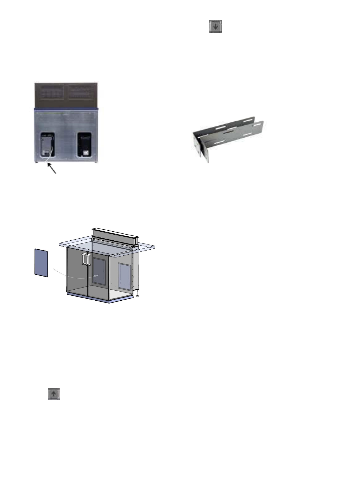
assembled with remote-controlled models. In
such cases, the antenna which is secured to the
back of the housing for transportation, must be
positioned to ensure a good radio link to the
portable transmitter.
Electrical connection for extraction mode Check
that the supply voltage corresponds to the
details on the rating plate.
For devices between 600 and 800 mm, the
controls are mounted on the front (filter side).
The connectors for the mains and ventilator are
located on the ventilator control. You require
two sockets for the power supply.
4
For devices between 900 and 1900 mm, the
controls are integrated in the device. The
connectors for the mains and ventilator are
located underneath the device. You require one
socket for the power supply.
The customer service must be able to access the
controls. Please provide two inspection openings
in the rear walls of kitchen furniture. Covers for
the inspection openings are included in the scope
of supply.
Electrical connection for recirculation mode
The controls are located on the rear or on the
left of the front side, next to the activated
carbon filters. The connectors for the mains and
ventilator are located on the ventilator control.
You require two sockets for the power supply.
Initial operation
Press the button, the device must move
upwards. Once it is in the upper position, you can
switch on the ventilation. Check all the functions.
Press the button, the device must move
downwards.
Should the hood not move, perform an
initialisation run (see page 6).
Move the hood several times and observe
whether the device runs in parallel.
After aligning the device and using for the first
time, secure it in a suitable place using the
mounting brackets supplied.
The brackets can be attached to the screws of
the device cladding or the screws in the side
parts. Attach the brackets as far down as
possible. The top of the device is fixed in place
in the work surface cut-out and can thus not
move. Should there be too much play here,
secure here as well to ensure that the device
remains stable.
If the downdraft ventilation is aligned in the
cut-out in the kitchen work surface and if the
loose cover is exactly flush with the work
surface in the lower position, you can also
adhere the cover to the mounting plate. The
cover must only be adhered to the mounting
plate and not to the housing. Make sure you
can still access the adjustable feet to allow
readjustment at a later date.
Subsequent minor adjustments can also be
made using both lifting cylinders. For this,
the upper cover must be removed.
The height can be adjusted by undoing the
fastening nut M10 and turning the setscrew
with an Allen key.
The tilt can be set by turning the magnets
5
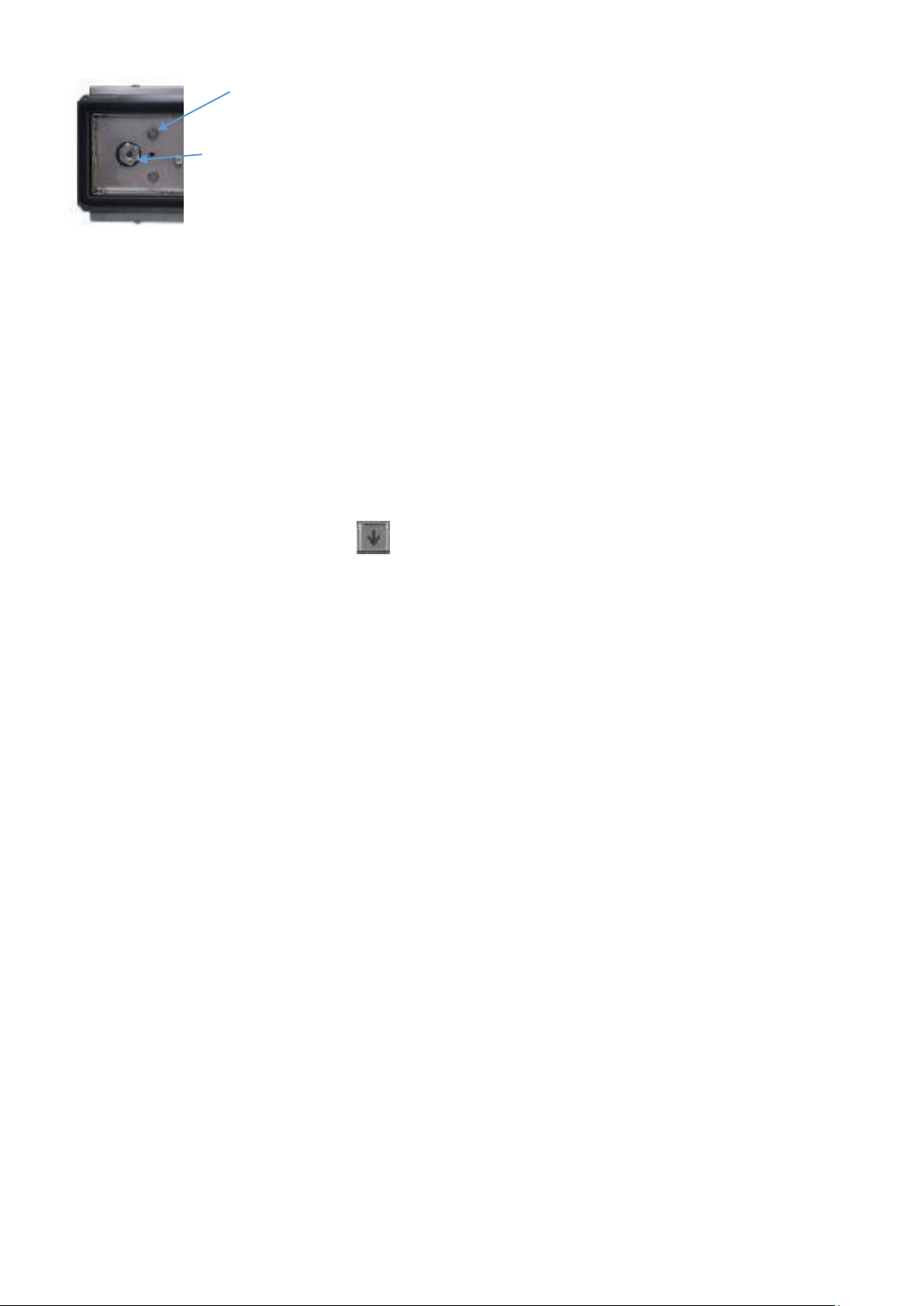
Magnet
Lifting cylinder attachment
Note
If work on the building site is not yet complete,
there is a risk that the device could be
operated by third parties. Dirt and sand grains
could fall between the guide and housing and
cause scratches. Disconnect the device from
the power supply during this time.
Initialisation run
Should the hood no longer move or the device
moves up and down at an angle, an
initialisation run must be performed.
The system is initialised by pressing the
button.
If must be depressed until the drives have
reached the bottom position.
Release for 5 seconds.
Hold down the button for a further 10
seconds.
The system is lowered slightly and lifted up
again during initialisation. The initialisation run
is then complete.
Please do not let go of the down button during
the initialisation run.
If you let go of this button before the run is
complete, this process is interrupted and must
be started again. If the initialisation run is
interrupted, the system cannot be moved
upwards. Should it not be possible to perform
an initialisation run, either the connecting
cables of both controls have been
disconnected, the lifting movement control is
faulty or a lifting cylinder is no longer working.
Maintenance
Firstly disconnect the device from the power
supply before performing any repairs or
maintenance work.
We hope you enjoy using your new extractor
fan.
6
Table of contents


