ENERGY SUPPORT CORPORATION CP-X User manual

Manual No.3010E R1
OPERATION MANUAL FOR
OVEN O2 ANALYZER MODEL
TYPE CP-X
READ THE OPERATION MANUAL.


Obsereve the following precautions without fail for safe operation of the equipment.
WARNING
1. When connecting cables to the terminals of the analyzer or when servicing inside the
analyzer, take care to avoid electric shock. When servicing electrical parts, be sure to turn
the power off.
2. Connect the grounding wire to prevent accidents caused by electric shock.
3. When fabricating the gas inlet/outlet pipes or disconnecting pipes for maintenance inside
the analyzer, be sure to shut off the gas source valve to prevent accidents caused by gas
intoxication or oxygen deficiency.
4. To prevent gas intoxication and oxygen deficiency, test gas leaks after fabricating the gas
inlet/outlet pipes or performing maintenance service of piping inside the analyzer.
Route the gas outlet at a safe place provided with the atmospheric pressure.
CAUTION
1. To prevent electric shock, before you turn on the power switch always check that the
power supply wiring is correctly and securely connected, and that the supply voltage
matches the power source voltage of this device.
2. To prevent gas intoxication or oxygen deficiency, before you open the gas source valve
always check that the gas inlet and outlet pipes of the analyzer are correctly and securely
connected, and check that there is no gas source valve.
3. To prevent burns, do not touch the transmission unit, sensor unit (detector, etc.) and their
periphery during operation and shortly after operation because there portions are very hot.
4. Be sure to close the gas source valve to perform maintenance services of the piping system
when the sample gas contains toxic contents to prevent gas intoxication.
5. Observe the cautions and operation methods described in this manual to operate this equipment
safety. If the description is neglected during operation of the equipment, electric shock, gas
intoxication, oxygen deficiency, burns, damage or deterioration of this equipment or damage to
the final product (device, etc.) may be caused.
Safety Precautions

Table of Contents
1. General ............................................................................................................... 1
2. Theory of measurement ...................................................................................... 1
3. Features of type CP-X O2 analyzer ..................................................................... 2
4. Specofocations .................................................................................................... 3
5. Names and functions of parts .............................................................................. 3
6. Installation work ............................................................................................. 3
7. Operation.............................................................................................................. 5
8. Inspection and maintenance ................................................................................ 6
9. Troubleeshooting .............................................................................................. 10
10. Attashed drawings ............................................................................................ 12
1
1. General
The reducing atmosphere oven O2 analyzer automatically measures the oven atmosphere inside a gives
the indication and signals of the measured value.
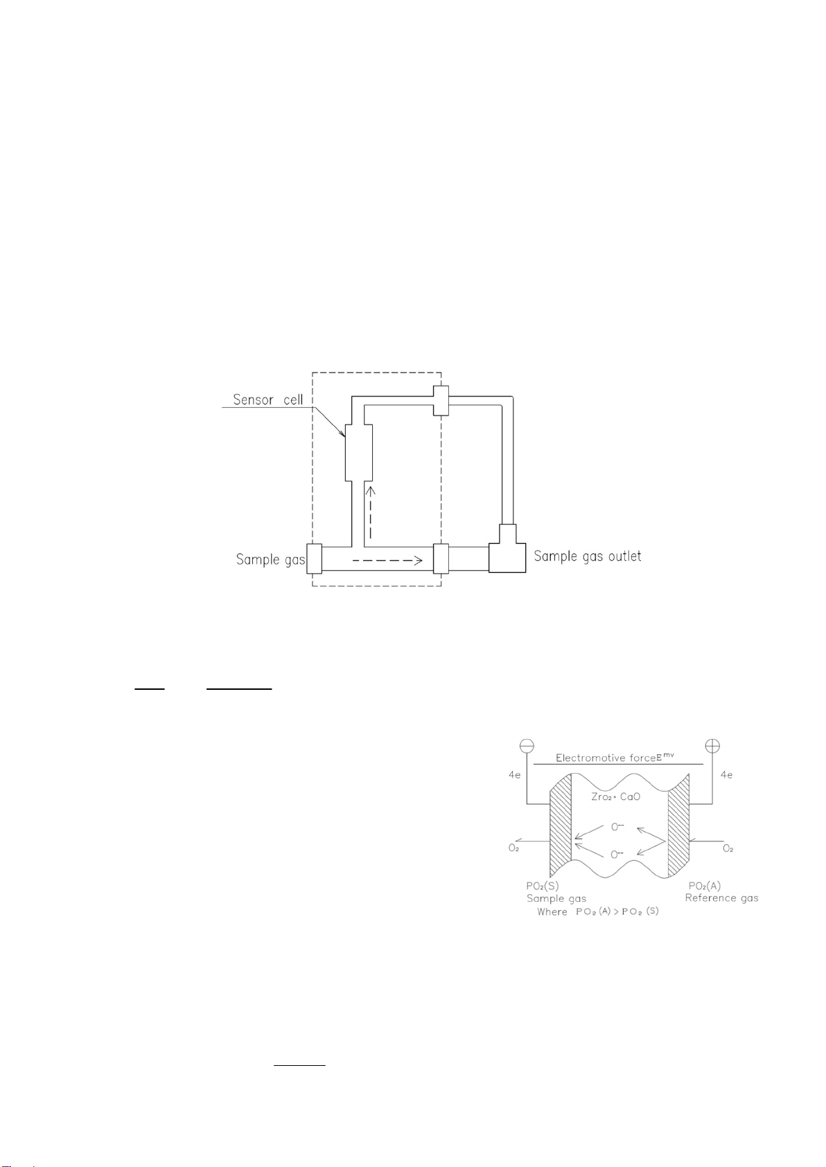
2. Theory of measurement
The type CP-X oxygen analyzer introduces the gas to be measured between the sample gas intake port
fitted on the oven wall and the outlet. Partial pressure of oxygen in the introduced sample gas is
measured with a sensor cell.
Fig. 1 Basic configuration
ig. 2 Principle of sensor cell operation
1
SPO
APO
In
F
RT
E
2
2 ・・・・・・・・
n
Where
E: Electromotive force (mV)
R: Gas constant
T: Absolute Temperature
F: Faraday constant
n: 4
PO2(A): O2 partial pressure in reference gas (0.206 atm)
PO2(S): O2 partial pressure in sample gas (atm)
(Normal atmospheric air is used as the reference gas)
By substituting these values into the equation (1), the following equation is obtained.
2
SPO
0.206
log10T49.6E
2
3- ・・・・・・・・・
10

2
Usually, the O2 partial pressure in the oven atmosphere which has been denatured by the supplied gas CH4,
C3H6, C4H10 etc. falls within 10-19~10-21 atm.
Relationship between the oven atmosphere and carbon potential is expressed as follows.
In the oven atmosphere reaction CO + 1/2 O2⇔CO2, the following equation holds:
1
2
2
1
2K
PCO
POPCO
・(K1:equilibrium constant)
2
1
2
1
2POPCO
K
1
PCO
In the oven atmosphere reaction CO2 + C ⇔2CO
2
2
2K
PCO
PCO
c
a (K2: equilibrium constant)
2
2
2PCO
PCO
K
c
a
By substituting PCO2 into the above equation, carbon potential ac is obtained as follows.
2
1
2
2
2
POPCO
K
1
1
PCOK
c
a
2
1
221 POPCOKK
Because PCO in the oven atmosphere remains constant, carbon potential can be obtained by measuring PO2
in the oven atmosphere.
3. Features of CP-X type O2 analyzer
(1)Maintenance-free
CP-X type O2 analyzer is subject to minimum drift and requires minimum maintenance in sampling.
(2)High sensitivity
High sensitivity enables detecting slight change in the oven atmosphere.
(3)Quick response
(4)Measurement by means of the sample gas in the flue allows a shorter sample line, making it free
from clogging.

3
4. Specifications
Model: CP-X type KS-16410□-□
Response time: Within 10 seconds (90% response)
Operating temperature range: Sensor unit -10~150℃
Power requirement: AC100±10V 260VA
Warm-up time: About 20 minutes
Insulation resistance: Sensor unit 100KΩ or over
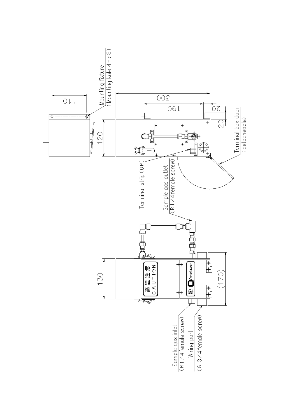
Dimensions: See the drawing.
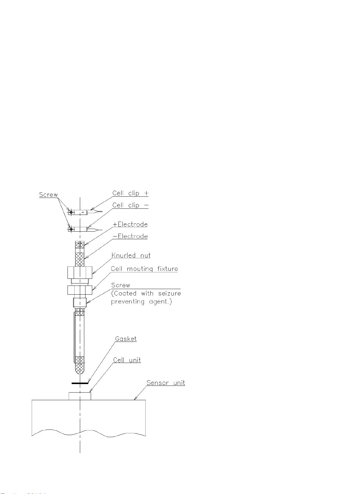
5. Names and functions of parts
5-1 Sensor unit
6. Installation work
6-1 Selection of gas sampling point
Select the sample gas intake point or the sensor unit mounting position, observing the following
conditions.
(1) Where the sampled gas shows the representative values.
(2) Where the gas is less likely to undergo quick change.
(3) Where a laminar flow of sample gas exists.
(4) Where the sensor unit is not subject to vibration or impact.
(5) Where maintenance service can be performed easily.
(6) Where ambient temperature is not higher than 150℃.

4
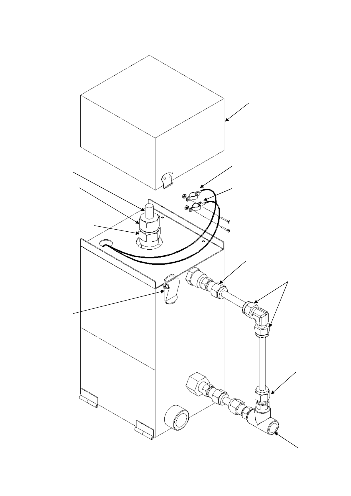
6-2 Wiring and piping (Reference)
Note: Piping and wiring shall be given due consideration to the following.
(1) Place signal wires (CELL R BR) and power wires (CMV, Heater, etc.) in a separate conduit.
(2) Do not use the cable exceeding 100m between the transmitter and receiver.
(3) As the terminal temperature in the transmitter goes up 70-80℃ above ambient, use R-compensated
wire connecting to the transmitter for thermocouple (R).
(4) Use shielded wires for signal lines.
(5) Make sure to ground the shield of the signal lines
(6) Type CP-X transmitter
① Use control copper tube (CUT φ10/φ8-6/φ4)and make the tube as short as possible and
without sharp bend, and connectors if possible.
② Pipe so that diversion type sample gas is discharged through flair bend. Adjust so that flame
length is 2-5 cm at the flair bend for the gas flow volume of 2-4L/min. This flair length
specification is based on the RX sample gas, which discharged to atmosphere through control
copper tube. For other specification, install flow meter upstream of the transmitter. The
recommended flow meter is Energy Support model KS-183019.
③ Make sure to install a drain filter in the sample gas piping.
④ Connect instrument air for purging to the transmitter using control copper tube
(CUTφ10/φ8-6/φ4)
⑤ Burn out the transmitter internal for 3-5 minutes with the compressed air of 2-4L/min once per
week. (Depending on the soot condition in the transmitter, maintain furnace temperature rise
due to soot burning at 850+30℃)
⑥ As soot at the low temperature part in the transmitter cannot be burnt out, remove it from the
cleaning hatch.

5
7. Operation
7-1 Inspection before operation
Check the following for the installations made in accordance to the instruction in 6. Installation work.
(1) Check the piping and wiring to see they are completed correctly in compliance to the drawings.
(2) Check with a DC500V megger to make sure of no earth leakage and insulation defect. Be sure to not
connect the control unit in this check.
*Across PR (R), CELL and case (ground): 100 KΩ or over
*Across OUT and case (ground): 10 MΩ or over
(3) Check to make sure that power voltage is 100 ±10V.
6
8. Inspection and maintenance
(1)Inspection of indicated value, recorder chart: once/3 days.
(2)Air purging from sensor unit and pipe line: once /week.
(3)Inspection for sticking material and clogging in sensor unit with the sensor unit disconnected:
Occasionally (guide line: once / 3 months).
(4)Take out the sensor unit and check the appearance with eyes.
Once/year.
Note : 1)In the event of a failure which may affect the measurement, replace the unit.
2)When removing the clogging in the sensor unit, pay great care to not damage the sensor cell.
(Replacement of sensor cell)
The sensor cell should be replaced in the following procedure after turning off the power to the electric oven
and the electric oven has cooled down enough.
a) Loosen the cell clip screw and remove the
cell clip.
b) Apply spanners to the cell mounting
fixture and the spanners flat and loosen
the cell mounting fixture
(counter-clockwise).When loosened, the
fixture is to be removed by turning it
manually.
c) Mount a spare sensor cell in the reverse
order of the disassembly.
Note: Handled the sensor cell with great care
as it may break when impact is applied.

7
8-1 Effects of sooting
Sooting causes the indication to lower below the normal measurement level, with the variation in the
indication diminishing.
When such a phenomenon as above is observed, carry out a burning out by means of air. (Carry out
burning out for a period at an interval which depends on the sooting condition.)
8-2 Burn-out procedure
(1) Keep the temperature of the type CP-X sensor unit controlled at 850℃
(2) Shut off the sample gas.
(3) Supply 2~4L/min of burn-out air.
(4) Keep the supply of burn-out air until the cell output (voltage across CELL + and - ) of the type CP-X
sensor unit becomes +10mV or below.
(5) Stop the burn-out air and supply 2~4L/min of sample gas to make measurement.
Note : Frequency of burning out
Frequency of burning out depends on the carbon potential of the sample gas and other factors, but
once per week is recommended as the guide line.
If the measuring instrument mentioned in (4) is not used, carry out burning out for about 30 minutes.
Burning out should be done to keep the sensor unit temperature within a range of 850 ±30℃.
OUTPUT
TIME
Sooting taking place
Burning out for at least one hour should be carried out at
every run of operation or once every three days
(whichever the more frequent).
8
8-3 Soot removal after disassembly
Case lid
Cell clip+
Spring clamp
Knurled nut
(Do not loosen)
Cell mounting fixture
Sensor cell
Cell clip-
Sample gas outlet pipe
Disassemble
Disassemble
Disassemble
Next page

9
(1) Shut off the sample gas.
(2) Supply 2~4L/min of burn-out air.
(3) Shut off the power to the type CP-X sensor unit and turn off the sensor unit heater power.
(4) Leave the sensor unit to stand for about 60 minutes.
(5) Undo the spring clamp of the type CP-X sensor unit and remove the case lid.
(6) Remove the cell clip from the sensor cell by using a + screw driver and a pair of long-nosed pliers.
(The upper one is the + cell clip.)
(7) Loosen the cell mounting fixture with a spanner or a monkey wrench.
(Do not loosen the knurled nut which is for sealing of the sensor cell.)
(8) Remove the sensor cell.
(9) Dismantle the sample gas outlet pipe and three blind plugs using a spanner or a monkey wrench.
(10) Remove soot from the inside of the sensor unit through the cell mounting seat, blind plug hole and the
sampled gas outlet pipe, by using a pipe of 5mm in O.D. or the like.
Note: Supplying purge air (0.05~0.1MPa) during the soot removal in (10) will be effective.
Measurement condition can be obtained by reversing the procedure above.
8-4 About sensor unit
・Because ISOWOOL BSSR BULK is used as a sensor unit of this product , we attach a safety data sheet of
ISOWOOL BSSR BULK. If you lose your safety data sheet , please contact our agent or our sales office.
10
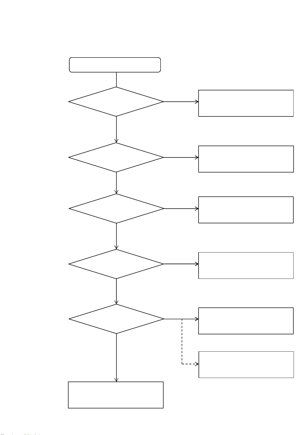
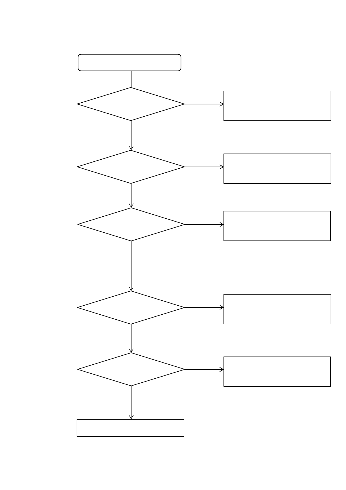
9. Troubleshooting
Response is excessively slow.
Is there leakage?
Is the STD inlet
plugged?
Is there sooting
in the oven?
Is the response
from sensor cell normal?
Is electric
oven temperature
normal?
Remove the clogging
(sensor unit , piping).
Adjust the electric oven
temperature to normal level.
Repair the leaking part.
Apply a blind plug to
STD inlet.
Remove the soot.
Replace the sensor cell
Test by supplying O2/N2 or
CO , Co2/N2 gas through
the STD gas inlet.
YES
NO
YES
YES
YES
YES
NO
NO
NO
NO
(1) Response is excessively slow.
11
Measurement indication is faulty.
Is the
response time normal?
Is the lead wire
connection unstable?
Is there clogging?
Is there sooting
in the oven?
Is the electric oven
temperature stable?
Change in the sample gas.
See para 8-2.
See para 8-3.
Repair the unstable connection.
Remove the clogging.
Remove the soot.
NO
YES
YES
YES
YES
YES
NO
NO
NO
NO
(2) Measurement indication is faulty.
12
10.Attashed drawings (Sensor unit)

13
EMF(mv) O2(%) EMF(mv) O2(%) EMF(mv) O2(%) EMF(mv) O2(%) EMF(mv) O2(%) EMF(mv) O2(%) EMF(mv) O2(%)
0 20.6 200 0.005287 400 1.36E-06 600 3.48E-10 800 8.94E-14 1000 2.29E-17 1200 5.89E-21
10 13.62492 210 0.003497 410 8.97E-07 610 2.30E-10 810 5.91E-14 1010 1.52E-17 1210 3.89E-21
20 9.011577 220 0.002313 420 5.94E-07 620 1.52E-10 820 3.91E-14 1020 1.00E-17 1220 2.58E-21
30 5.960293 230 0.00153 430 3.93E-07 630 1.01E-10 830 2.59E-14 1030 6.64E-18 1230 1.70E-21
40 3.942161 240 0.001012 440 2.60E-07 640 6.66E-11 840 1.71E-14 1040 4.39E-18 1240 1.13E-21
50 2.607361 250 0.000669 450 1.72E-07 650 4.41E-11 850 1.13E-14 1050 2.90E-18 1250 7.45E-22
60 1.724519 260 0.000443 460 1.14E-07 660 2.92E-11 860 7.48E-15 1060 1.92E-18 1260 4.93E-22
70 1.140604 270 0.000293 470 7.51E-08 670 1.93E-11 870 4.95E-15 1070 1.27E-18 1270 3.26E-22
80 0.7544 280 0.000194 480 4.97E-08 680 1.28E-11 880 3.27E-15 1080 8.40E-19 1280 2.16E-22
90 0.498963 290 0.000128 490 3.29E-08 690 8.43E-12 890 2.16E-15 1090 5.56E-19 1290 1.43E-22
100 0.330016 300 8.47E-05 500 2.17E-08 700 5.58E-12 900 1.43E-15 1100 3.67E-19 1300 9.43E-23
110 0.218274 310 5.60E-05 510 1.44E-08 710 3.69E-12 910 9.47E-16 1110 2.43E-19 1310 6.24E-23
120 0.144367 320 3.71E-05 520 9.51E-09 720 2.44E-12 920 6.26E-16 1120 1.61E-19 1320 4.13E-23
130 0.095485 330 2.45E-05 530 6.29E-09 730 1.61E-12 930 4.14E-16 1130 1.06E-19 1330 2.73E-23
140 0.063154 340 1.62E-05 540 4.16E-09 740 1.07E-12 940 2.74E-16 1140 7.03E-20 1340 1.80E-23
150 0.04177 350 1.07E-05 550 2.75E-09 750 7.06E-13 950 1.81E-16 1150 4.65E-20 1350 1.19E-23
160 0.027627 360 7.09E-06 560 1.82E-09 760 4.67E-13 960 1.20E-16 1160 3.08E-20 1360 7.89E-24
170 0.018273 370 4.69E-06 570 1.20E-09 770 3.09E-13 970 7.93E-17 1170 2.03E-20 1370 5.22E-24
180 0.012086 380 3.10E-06 580 7.96E-10 780 2.04E-13 980 5.24E-17 1180 1.35E-20 1380 3.45E-24
190 0.007993 390 2.05E-06 590 5.27E-10 790 1.35E-13 990 3.47E-17 1190 8.90E-21 1390 2.28E-24
2
2
10
3
2%6.20
log850273106.49 O
O
EMFOEMFXCP
n
10n-E


Repairs request slip for measuring apparatus
ENERGY’s
entry column
SV-
Please Notice for customers following contents
through facsimile or telephone.
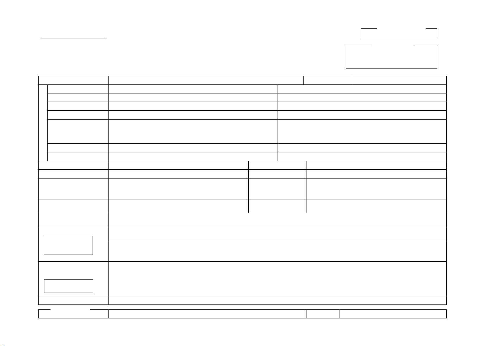
Measuring instrument repair request sheet (product send-back sheet)
If the contents of the repair request are insufficient when sending your product back to ENERGY for
repair, it takes a long time to perform the acceptance inspection, causing inconvenience in delivery.
Always carefully check the following items before sending back the product.
Additionally, please write your company name and your local sales representative name in columns
stated on the next page.
Symptom check columns
Class
Symptom
Check
applicable
part.
Class
Symptom
Check
applicable
part.
Indication
and
display
Indication does not change
(always zero).
Alarm
display
and
contact
output
Error is displayed. Error number( )
( )
Indication does not change (except
for zero/span point).
Error lamp is lit.
Indication overshoots the scale
(span side).
Error contact output is output
even though the error (display or
lamp) is not shown.
Indication fluctuates largely.
Indication changes suddenly.
Error contact output is not output
even though an error occurs.
Indication is too high.
Error is not displayed even though
an error occurs.
Indication is too low.
Error lamp does not light up even
though an error occurs.
Key
operation
Range cannot be changed.
Response
Too fast.
Key operation cannot be made.
Too fast even with the time
constant multiplied.
Data cannot be set.
Too slow.
Data is not saved (input) to the
memory.
Calibration
Span-point calibration cannot be
made.
Data cannot be changed.
Indication is unstable during span-
point calibration.
Please write not applied contents in symptom check columns and investigated contents in the following
columns.
ENERGY SUPPORT CORPORATION
Industrial system Division
FAX : 0568-67-1842
Tel. : 0568-67-2743
Address: 1,Aza Kamikobari,Inuyama,
Aichi 484-8505
ORDER SHEET to repair INSTRUMENT PRODUCTS (Usable as INVOICE SHEET)
Order items
Repair, Return, Test, Regular Maintenance
Order date
20 . .
Liaison section & person of customer
Agent
Customer
Company
Division
Person
Address
Tel. Number
FAX Number
Product Name (Model Name)
Installed plant
Accessory Name
Serial number
Device Number
(Analyzer board)
Analyzer model number
( Transmitter ・Receiver )
Delivery date
Delivery date
(instrument)
Operation conditions
Measuring range :
Gas temperature:
Measuring concentration :
Gas pressure :
Situations of troubles
Date and time of event occurrence:
At heating up, steady running, cooling down, investgating others( )
Investigated contents
by your engineers
〔Investigated items〕
〔investigated results〕
Preparing situation by customer
Order number
Please get in touch with QC team of Measurement System Marketing Department Industrial System Division ENERGY SUPPORT.
Private description
Please describe detail
points of malfunctions
and troubled situations
What and how did you
investigated?
In terms of contents mentioned
below please get in touch with us
by means of FAX or Telephone.
※To customer
※
SV-
Private description
Table of contents
Popular Oven manuals by other brands

Indesit
Indesit FG10KBK.1 Instructions for installation and use

Wood Stone
Wood Stone TRADITIONAL Series Installation and operation manual

Miele
Miele DGC 6705 XL installation guide

DeLonghi
DeLonghi EO400 Instructions for use

Clatronic
Clatronic MBG 3726 instruction manual

Wood Stone
Wood Stone MT. CHUCKANUT Installation and operation manual

GE
GE Monogram ZET837BYBB Technician manual

Fulgor Milano
Fulgor Milano FCSO 4511 TM manual

Whirlpool
Whirlpool AKZ 561 User and maintenance manual

Garland
Garland Mealstream 501 Installation and operating instructions

Parmco
Parmco FS900SC Installation and operating instructions

Hanseatic
Hanseatic 6467 5200 user manual


