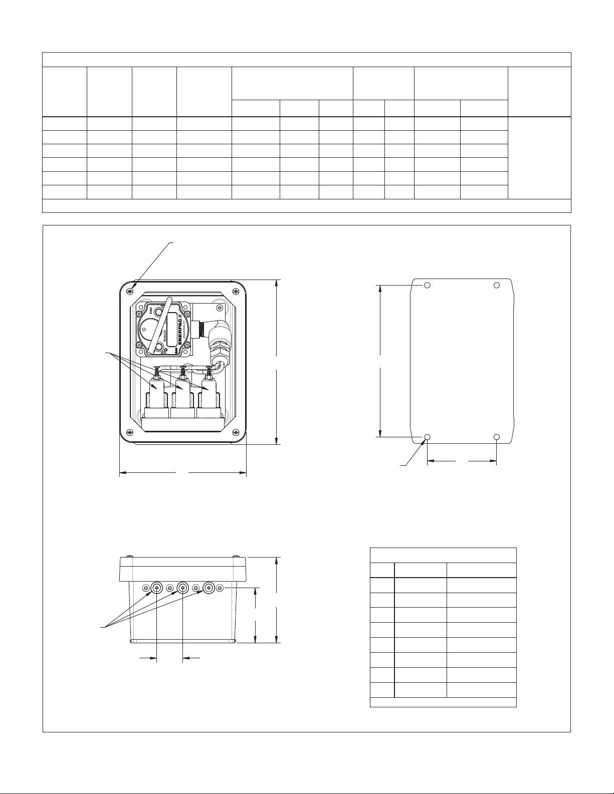
Enerpac SLE-18 User manual

POWERFUL SOLUTIONS. GLOBAL FORCE.
Instruction Sheet
SafeLink Send Unit with Enclosure
Models SLE-18, SLE-19, SLE-28,
SLE-29, SLE-38 and SLE-39
1.0 IMPORTANT RECEIVING INSTRUCTIONS
Visually inspect all components for shipping damage. Shipping
damage is not covered by warranty. If shipping damage is found,
notify carrier at once. The carrier is responsible for all repair and
replacement costs resulting from damage in shipment.
2.0 SAFETY
Read all instructions carefully. Follow all recommended safety
precautions to avoid personal injury as well as damage to the
product and/or damage to other property. Enerpac cannot be
responsible for any damage or injury from unsafe use, lack of
maintenance or incorrect operation. Do not remove warning labels,
tags, or decals. In the event any questions or concerns arise,
contact Enerpac or a local Enerpac distributor for clarification.
If you have never been trained on high-pressure hydraulic safety,
consult your distributor or service center for a free Enerpac
Hydraulic Safety Course.
This manual follows a system of safety alert symbols, signal words
and safety messages to warn the user of specific hazards. Failure
to comply with these warnings could result in death or serious
personal injury, as well as damage to the equipment or other
property.
The Safety Alert Symbol appears throughout this manual.
It is used to alert you to potential physical injury hazards.
Pay close attention to Safety Alert Symbols and obey all
safety messages that follow this symbol to avoid the possibility of
death or serious personal injury.
Safety Alert Symbols are used in conjunction with certain Signal
Words that call attention to safety messages or property damage
messages and designate a degree or level of hazard seriousness.
The Signal Words used in this manual are DANGER, WARNING,
CAUTION and NOTICE.
DANGER Indicates a hazardous situation that, if not
avoided, will result in death or serious personal
injury.
WARNING Indicates a hazardous situation that, if not
avoided, could result in death or serious personal
injury.
CAUTION Indicates a hazardous situation that, if not
avoided, could result in minor or moderate
personal injury.
NOTICE Indicates information considered important, but
not hazard related (e.g. messages relating to
property damage). Please note that the Safety
Alert Symbol will not be used with this signal
word.
WARNING
Failure to observe the following precautions and instructions
may result in death or serious personal injury:
• Make no modifications to any SafeLink component. Any
modifications to the product not expressly approved by Enerpac
could void the user’s authority to operate the product. Contact
Enerpac factory for more information.
• SafeLink products must only be serviced by a qualified electronic
technician. For factory authorized repair service, contact the
ENERPAC Authorized Service Center in your area.
• Never use any component of the SafeLink system as a sensing
device for personal protection. Doing so could lead to serious injury
or death. The SafeLink system does NOT include the self-checking
redundant circuitry necessary to allow its use in personal safety
applications. A sensor failure or malfunction can cause either an
energized or de-energized sensor output condition.
• Some SafeLink components are powered by a 3.6 volt lithium
battery. As with all batteries, there is a fire, explosion, and severe
burn hazard risk. Do not burn or expose the battery to high
temperatures. Do not recharge, crush, disassemble, or expose the
contents to water.
• All live supply circuits must be disconnected before wiring the
machine control.
• Be certain that all pressure is completely relieved (0 psi/bar)
before loosening hydraulic fittings or disconnecting hydraulic lines.
• To avoid personal injury, keep hands and feet away from fixture
cylinder(s) and workpiece during operation.
NOTICE All specifications published in this document are subject
to change. Enerpac reserves the right to modify the specifications
of products without notice. Enerpac reserves the right to update or
change documentation at any time.
L4142 Rev. A 09/15
1

Table 1 - SafeLink SLE Series Specifications
SafeLink
Enclosure
Model
Send Unit
Model
Pressure
Switch
Model
Number of
Pressure
Switches
(Hyd. Inputs)
Pressure Switch
Setting Range* Weight Operating Temp Range Enclosure
Ratings
psi bar MPa lb kg °F °C
SLE-18 SLS-3 PSCK-8 1 1450-5000 100-345 10-35 6.0 2.7 -4 to +176 -20 to +80
NEMA14
partial
submersion
IEC 60529
(IP66)
SLE-19 SLS-3 PSCK-9 1 290-3045 20-210 2-21 6.0 2.7 -4 to +176 -20 to +80
SLE-28 SLS-3 PSCK-8 2 1450-5000 100-345 10-35 6.5 2.9 -4 to +176 -20 to +80
SLE-29 SLS-3 PSCK-9 2 290-3045 20-210 2-21 6.5 2.9 -4 to +176 -20 to +80
SLE-38 SLS-3 PSCK-8 3 1450-5000 100-345 10-35 7.0 3.2 -4 to +176 -20 to +80
SLE-39 SLS-3 PSCK-9 3 290-3045 20-210 2-21 7.0 3.2 -4 to +176 -20 to +80
* Maximum input pressure is 5000 psi [345 bar].
3.0 PRODUCT DATA
22
Figure 1, Mounting Dimensions
❉
A
B
C
D
E
F
G
H
✤
Dimensions
Item inch mm
A9.5 241
B7.3 185
C4.9 124
D3.2 81
E1.5 38
F8.8 224
G4.0 102
HØ 0.33 Ø 8.4
Note: All dimensions are approximate.
Mounting Holes
(viewed from rear)
❉Hydraulic Input Ports #2 SAE
(port is functional only if
pressure switch is installed)
Torque cover screws to 14-16 in-lb [1.6-1.8 Nm] using
opposite corners sequence.
✤Hydraulic Pressure Switches
(1, 2 or 3, depending on enclosure model)
(4 places)

4.0 PRODUCT DESCRIPTION
The SafeLink SLE Series send unit with enclosure is designed
to monitor fixture pressure and clamp position in real time, even
when parts are being machined. The unit can also be used to
verify that the operator has properly pressurized the fixture
before it is sent inside the machining center.
Major components include:
• Protective enclosure with cover.
• Enerpac SafeLink SLS-3 send unit.
• Enerpac pressure switches, Model PSCK-8 or PSCK-9 (switch
model and quantity of switches installed varies, depending on
enclosure model). Pressure switches are factory installed and
pre-wired to the SLS-3 send unit.
• Pressure switch manifold with input ports.
• Desiccant pack (for moisture protection).
See Section 3.0 of this manual for complete SLE Series product
specifications and dimensions.
For detailed operating instructions and additional information
regarding the SLS-3 send unit, refer to the SafeLink Pallet
Monitoring System Instruction Sheet (Enerpac document L3080).
NOTICE To make a complete SafeLink system, one SafeLink
SLR-2 receive unit is also required. The SLR-2 receive unit is not
included and must be purchased separately.
5.0 ENCLOSURE INSTALLATION
NOTICE These instructions are intended only for use by
experienced installation technicians with appropriate skills and
training. If custom installation services are required, contact your
Enerpac representative for additional information.
5.1 Installing the Send Unit Enclosure on a Fixture
The send unit enclosure can be mounted anywhere on the fixture,
including locations that are exposed to coolant flow or flying
chips. The enclosure is IEC rated at IP66, protected from dust
and strong jets of water or coolant. If necessary, the enclosure
can be placed in direct contact with coolant streams.
NOTICE Be certain that the enclosure is mounted in a location
where the send unit’s antenna can transmit freely without
interference. The enclosure must not be installed in a location on
the fixture that is totally enclosed in metal.
The enclosure can be oriented in either the horizontal or vertical
position. Use all four holes of the enclosure mounting flange to
securely install the unit (fasteners are user-supplied).
NOTICE To prevent damage to the mounting flange holes, use
appropriate size fasteners and do not over torque. Over torquing
could crack the flange.
The SLS-3 send unit is secured to the enclosure back plate by
Velcro strips. It should be positioned to allow the best view of the
display and controls.
33
Figure 2, Features and Components
SLE-18, SLE-19
SLE-38, SLE-39
1
2
6
8
7
9
4
3
5
10
SLE-28, SLE-29
Key:
1. SLS-3 Send Unit
2. Pressure Switch 1 (standard)
3. Pressure Switch 2 (optional)
4. Pressure Switch 3 (optional)
5. SAE #2 Ports
6. Manifold
7. Enclosure with Cover
8. Desiccant Pack
9. Velcro Strips
10. Antenna

4
5.2 Hydraulic Connections
The hydraulic input ports are standard #2 SAE connections
located on the bottom panel of the enclosure. Always use good
engineering practices when making hydraulic connections.
Maintain cleanliness to prevent contamination.
Oil system contamination can result in improper operation and
accelerated wear of hydraulic components. To help prevent
contamination, ensure that all external connections are properly
made and leak tested. Be sure that plugs remain tightly installed
in any unused ports.
NOTICE Maximum operating pressure is 5000 psi [345 bar].
To avoid possible damage to the enclosure mounted hydraulic
components, be sure that hydraulic input pressure does not
exceed 5000 psi [345 bar].
6.0 START-UP PROCEDURE
Before placing the send unit and enclosure into service:
1. Validate the setting of each pressure switch (one, two
or three switches, depending on enclosure model) to
ensure that the switch is set to the desired pressure. This
process is described in Section 7 of this manual. Additional
information about the pressure switches can be found
in the PSCK Pressure Switch Instruction Sheet (Enerpac
document L2391).
2. After checking the pressure switch settings, make the
required hydraulic connections between the pressure
switches and the fixture. After making connections,
pressurize the input lines gradually to the machine working
pressure setting. Verify that there are no oil leaks.
3. Before operation, the SLS-3 send unit must be properly
“paired” with an SLR-2 receive unit. For complete
instructions regarding the SafeLink start-up and pairing
procedure, refer to the SafeLink Pallet Monitoring System
Instruction Sheet (Enerpac document L3080).
7.0 PRESSURE SWITCH INFORMATION
7.1 Introduction
As a precaution, and to ensure proper operation, always validate
the pressure setting of each pressure switch before placing the
SLS-3 send unit into service.
7.2 Adjusting and Validating the Pressure Switch Setting
All SafeLink SLE Series enclosures include at least one factory
pre-installed pressure switch. Up to two additional pressure
switches can be ordered as optional equipment.
Adjust and validate the setting of each pressure switch as
described in the following steps:
1. Remove plug from hydraulic input port. Use a 1/8 inch Allen
wrench. See Figure 3.
2. Connect a hand pump and 0-5000 psi [0-345 bar] pressure
gauge to the hydraulic input port (SAE #2 connection).
NOTICE If desired, the machining center hydraulic system
can be used in place of a hand pump. To allow verification of
hydraulic pressures in the following steps, the hydraulic system
must be equipped with a pressure gauge.
SAE #2 ports
with protective plugs.
Figure 3, Hydraulic Input Ports
(viewed from bottom of enclosure)
LED #2 will
flash RED.
Press and hold Button #1
for about three seconds
to turn-on unit.
Figure 4, SLS-3 Send Unit Controls
3. To gain access to the SLS-3 send unit controls, remove the
four screws securing the enclosure cover. Remove the cover
from the enclosure.
4. Press and hold Button #1 on the SLS-3 send unit for about
3 seconds. See Figure 4.
•The display window will scroll though the status of each
possible I/O. LED #2 will flash red.
•The send unit will then scroll through multiple screens
(NODE 1, I/O 1, OFF. . .).
NOTICE The following instructions assume that the pressure
setting is being adjusted for the pressure switch connected to
I/O 1 (first pressure switch). However, the procedure is similar for
I/O 2 (second pressure switch) and I/O 3 (third pressure switch).
5. Be certain that the hydraulic input line (from the pump) is
connected to the pressure switch, but not pressurized.
Pressure gauge should indicate 0 psi/bar.

5
Adjustment
Screw
Lock Nut
Figure 5, Pressure Switch Setting Adjustment
NOTICE Two 10 mm wrenches are required to complete the
pressure setting adjustment described in steps 6 thorough 12.
6. Loosen the pressure switch lock nut by turning it counter-
clockwise. See Figure 5.
7. Turn the adjustment screw counter-clockwise until the
screw is backed-out completely. This will ensure that the
pressure setting is at its lowest level.
NOTICE Starting from the lowest possible setting will result in
a more accurate setting for the desired pressure.
8. Before pressurizing the hydraulic input line, view the SLS-3
send unit display and verify that I/O 1 is “OFF”. (I/O 2 for
second pressure switch, I/O 3 for third pressure switch).
9. Pressurize the hydraulic input line gradually to the machining
center’s minimum working pressure setting. In most cases,
this will be the operating pressure minus a user-determined
acceptable pressure drop.
10. View the SLS-3 send unit display and verify that I/O 1 has
changed from “OFF” to “ON” (I/O 2 for second pressure
switch, I/O 3 for third pressure switch).
11. While viewing the SLS-3 send unit display, slowly turn the
adjustment screw clockwise until I/O 1 changes from “ON”
to “OFF”. This will simulate a hydraulic pressure release at
the desired setting (I/O 2 for second pressure switch, I/O 3
for third pressure switch).
12. While holding the adjustment screw with a wrench (so that it
does not turn), use a second wrench to tighten the lock nut
clockwise to 3 ft-lb [4 Nm].
13. If the send unit enclosure contains additional pressure
switches, repeat steps 1 though 12 for each remaining
pressure switch.
14. Reinstall the enclosure cover after all pressure adjustments
have been completed. Torque the cover screws to
approximately 14-16 in-lb [1.6 to 1.8 Nm].
8.0 MAINTENANCE
8.1 Enclosure
The enclosure protects the SLS-3 send unit, pressure switches
and manifold against coolant spray and other harsh conditions
which may occur in the manufacturing environment. It is
maintenance free and corrosion resistant.
8.2 Removing and Installing the Enclosure Cover
To ensure that the components inside the enclosure remain
protected, always reinstall the enclosure cover and use all 4
cover screws (supplied with unit). Torque the cover screws to
14-16 in-lb [1.6 to 1.8 Nm].
NOTICE To prevent damage to components inside the
enclosure, always be sure that the cover is fully secured with
all four screws tightened to the proper torque. Never allow
machining center operation while the cover is loose or removed.
8.3 Desiccant Pack Replacement
The inside of the enclosure must remain condensation free.
Condensation could damage the SLS-3 send unit and the other
components inside the enclosure.
The use of a desiccant packet is recommended to absorb
any condensation which may form inside the enclosure. The
desiccant packet is a consumable and should be replaced
immediately if condensation is found inside the enclosure.
Frequency of desiccant packet replacement will vary, depending
on the operating environment.
Check the enclosure for condensation at initial start-up and
periodically during the following months to determine the proper
replacement interval for the desiccant pack. Desiccant packs
are readily available from many industrial supply sources and are
not offered by Enerpac.
8.4 Send Unit Battery Replacement
The SLS-3 send unit battery has a 2 to 3 year expected life.
Battery replacement procedures can be found in the SafeLink
Pallet Monitoring System Instruction Sheet (Enerpac document
L3080).
The SLS-3 send unit attaches to the enclosure back plate using
Velcro strips. This Velcro mounting allows the SLS-3 send unit to
be easily detached and re-attached to the enclosure back plate,
simplifying the battery replacement procedure.
9.0 PRODUCT WARRANTY
SafeLink products are warranted by Enerpac to be free from
defects in material and workmanship for 2 years following the
date of shipment. Enerpac will repair or replace, free of charge,
any SafeLink product which, at the time it is returned to the
factory, is found to have been defective during the warranty.
THIS LIMITED WARRANTY IS EXCLUSIVE AND IN LIEU OF
ALL OTHER WARRANTIES WHETHER EXPRESS OR IMPLIED
(INCLUDING, WITHOUT LIMITATION, ANY WARRANTY
OF MERCHANTABILITY OR FITNESS FOR A PARTICULAR
PURPOSE), AND WHETHER ARISING UNDER COURSE OF
PERFORMANCE, COURSE OF DEALING OR TRADE USAGE.
This Warranty is exclusive and limited to repair or, at the discretion
of Enerpac, replacement. IN NO EVENT SHALL ENERPAC BE
LIABLE TO BUYER OR ANY OTHER PERSON OR ENTITY FOR
ANY EXTRA COSTS, EXPENSES, LOSSES, LOSS OF PROFITS,
OR ANY INCIDENTAL, CONSEQUENTIAL OR SPECIAL
DAMAGES RESULTING FROM ANY PRODUCT DEFECT OR
FROM THE USE OR INABILITY TO USE THE PRODUCT,
WHETHER ARISING IN CONTRACT OR WARRANTY, STATUTE,
TORT, STRICT LIABILITY, NEGLIGENCE, OR OTHERWISE.
Enerpac reserves the right to change, modify or improve the
design of the product without assuming any obligations or
liabilities relating to any product previously manufactured by
Enerpac.

6
NOTES:

7
NOTES:

Australia and New Zealand
Actuant Australia Ltd.
Block V Unit 3
Regents Park Estate
391 Park Road
Regents Park NSW 2143
(P.O. Box 261) Australia
T +61 (0)2 9743 8988
F +61 (0)2 9743 8648
Brazil
Power Packer do Brasil Ltda.
Rua
Luiz Lawrie Reid, 548
09930-760
-
Diadema (SP) - Brazil
T +55 11 5687 2211
Toll Free: 0800 891 5770
China
Actuant (China) Industries Co. Ltd.
No. 6 Nanjing East Road,
Taicang Economic Dep Zone
Jiangsu, China
T +86 0512 5328 7500
F +86 0512 5335 9690
Toll Free: +86 400 885 0369
France, Switzerland, North Africa
and French speaking African
countries
ENERPAC
Une division d’ACTUANT France S.A.S.
ZA de Courtaboeuf
32, avenue de la Baltique
91140 VILLEBON /YVETTE
France
T +33 1 60 13 68 68
F +33 1 69 20 37 50
Germany and Austria
ENERPAC GmbH
P.O. Box 300113
D-40401 Düsseldorf
Willstätterstrasse 13
D-40549 Düsseldorf, Germany
T +49 211 471 490
F +49 211 471 49 28
India
ENERPAC Hydraulics (India) Pvt. Ltd.
No. 10, Bellary Road,
Sadashivanagar,
Bangalore,
Karnataka
560 080
India
T
www.enerpac.com
Italy
ENERPAC S.p.A.
Via Canova 4
20094 Corsico (Milano)
T +39 02 4861 111
F +39 02 4860 1288
Japan
Applied Power Japan LTD KK
Besshocho 85-7
Kita-ku, Saitama-shi 331-0821, Japan
T +81 48 662 4911
F +81 48 662 4955
Middle East, Egypt and Libya
ENERPAC Middle East FZE
Oce 423, LOB 15
P.O. Box 18004, Jebel Ali, Dubai
United Arab Emirates
T +971 (0)4 8872686
F +971 (0)4 8872687
Russia
Rep. oce Enerpac
Russian Federation
Admirala Makarova Street 8
125212 Moscow, Russia
T +7 495 98090 91
F +7 495 98090 92
Southeast Asia, Hong Kong
and Taiwan
Actuant Asia Pte Ltd.
83 Joo Koon Circle
Singapore 629109
T +65 68 63 0611
F +65 64 84 5669
South Korea
Actuant Korea Ltd.
3Ba 717, Shihwa Industrial Complex
Jungwang-Dong, Shihung-Shi,
Kyunggi-Do
Republic of Korea 429-450
T +82 31 434 4506
F +82 31 434 4507
Spain and Portugal
ENERPAC SPAIN, S.L.
Avda. Los Frailes, 40 – Nave C & D
Pol. Ind. Los Frailes
28814 Daganzo de Arriba
(Madrid) Spain
T +34 91 884 86 06
F +34 91 884 86 11
Sweden, Denmark, Norway,
Finland and Iceland
Enerpac Scandinavia AB
Kopparlundsvägen 14,
721 30
Västerås
Sweden
T +46 (0) 771 41
The Netherlands, Belgium,
Luxembourg,
Central and Eastern Europe,
Baltic States, Greece, Turkey
and CIS countries
ENERPAC B.V.
Galvanistraat 115, 6716 AE Ede
P.O. Box 8097, 6710 AB Ede
The Netherlands
T +31 318 535 911
F +31 318 535 848
Enerpac Integrated Solutions B.V.
Spinelstraat 15, 7554 TS Hengelo
P.O. Box 421, 7550 AK Hengelo
The Netherlands
T +31 74 242 20 45
F +31 74 243 03 38
integr[email protected]
South Africa and other English
speaking African countries
Enerpac Africa Pty Ltd.
No. 5 Bauhinia Avenue
Cambridge Oce Park
Block E
Highveld Techno Park
Centurion 0157
Republic of South Africa
T: +27 12 940 0656
United Kingdom and Ireland
ENERPAC UK Ltd.
5 Coopies Field
Morpeth, Northumberland
NE61 6JR, England
T +44 (0)
1670 5016 50
F +44 (0) 1670 5016 51
USA, Latin America and Caribbean
ENERPAC World Headquarters
P.O. Box 3241
Milwaukee WI 53201-3241 USA
T +1 262 293 1600
F +1 262 293 7036
User inquiries:
T +1 800 433 2766
Distributor inquiries/orders:
T +1 800 558 0530
F +1 800 628 0490
Technical inquiries:
082615
50 00
N86 W12500 Westbrook Crossing
Menomonee Falls, Wisconsin 53051
Toll Free: +1800 363 7722
(Taicang)
+91 80 3928 9000
All Enerpac products are
guaranteed against defects
in workmanship and materials
for as long as you own them.
For the location of your nearest
authorized Enerpac Service Center,
visit us at www.enerpac.com
This manual suits for next models
5
Table of contents