Enertech Bentone BG 450 Technical specifications

Providing sustainable energy solutions worldwide
178 011 75-2 2016-11-28
Installation- and maintenance instruction
BG 450


!
Warning
DESCRIPTION
Warning
172 155 15 07-01
- Read the manual before assembling or commissioning.
- The contents of this manual are to be observed by all who work for any reason
on the unit and its appertaining system parts.
- This manual is intended especially for authorised personnel.
- This manual is to be regarded as part of the burner and shall always be
available near the place of installation.
- The burner is only to be installed by qualified personnel
- Check that the burner is suitable for the boiler´s power range.
- The burner is to be installed such that it complies with any local regulations
relating to electrical safety, boilers and fuel distribution.
- Check that the burner is approved for the gas quality intended used.
- No burner safety systems are to be disengaged.
- The fitter is to ensure that the boiler room is supplied with fresh air ventilation
that is sufficient in accordance with local standards.
- Before servicing, shut off the fuel supply and the power supply to the burner.
- The outer temperature of the boiler´s components can exceed 60 °C.
- Check that the guide stop is installed before servicing.
- Take great care when servicing. Trap and pinch risks can be present.
- The boiler´s sound level can exceed 85 dBA during operation. Use ear
protectors when present in the boiler room.
Safetydirections - The electrical installation shall be made according to valid regulations for
heavy current and in a professional way, so that the risk of leaking gas, fire
or personal injury is avoided.
- If another electrical connection is used than the one recommended by
Enertech, there might be a risk of material damage or personal injury.
- Notice should be carefully taken by the installer that no electrical cables or
gas pipes get squeezed or damaged when installing or at service
- If the boiler is provided with an opening door, this should be interlocked with
a door switch.
Acceptanceinspection - Ensure that everything is delivered and that there is no transport
damage.
- If there is anything wrong with the delivery, please report it to the supplier.
- Any transport damage should be reported to the forwarding company.
Preparations for installation - Ensure that the size and capacity range of the burner are suitable for the
boiler.
- Power data on the data plate refer to the minimum and maximum power of
the burner.
172 205 92 99-02
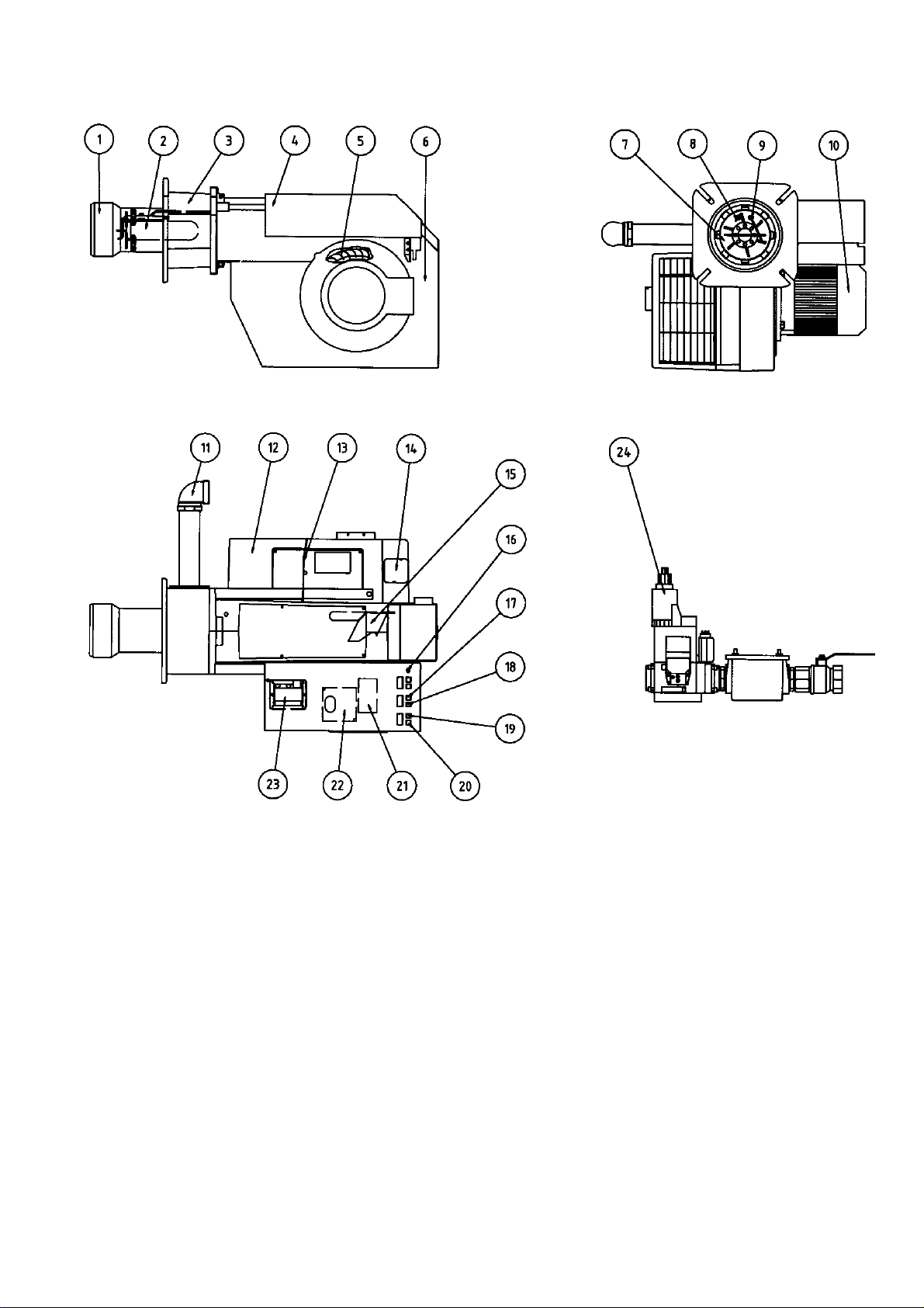
DESCRIPTION
COMPONENTS
1. Flame cone
2. Inner assembly
3. Fixing flange
4. Electric panel
5. Fan wheel
6. Fan house
7. Shrouded disc
8. Ignition electrode
9. Ionisation electrode
10. Motor
18. Switch l-ll
(For modulating burner:
Change-over switch manually-
automatically)
19. Indicating lamp Stage 1
20. Switch 0-1
21. Contactor
22. Control box
23. Ignition transformer
24. MultiBloc
11. Connection gas fittings
12. Air intake
13. Air damper
14. Air pressure switch
15. Conical shield plate
16 Fuse
17. Indicating lamp Stage 2
(For modulating burner:Change-
over switch increase-decrease)
Armatur 2) Motor Ignition transformer
Natural gas LPG 1-fas, 450W, 2 800 r/m, Primary 230 V, 1 A
1 1/2" 230/240 V Secondary 8 000 V
2) Town gas
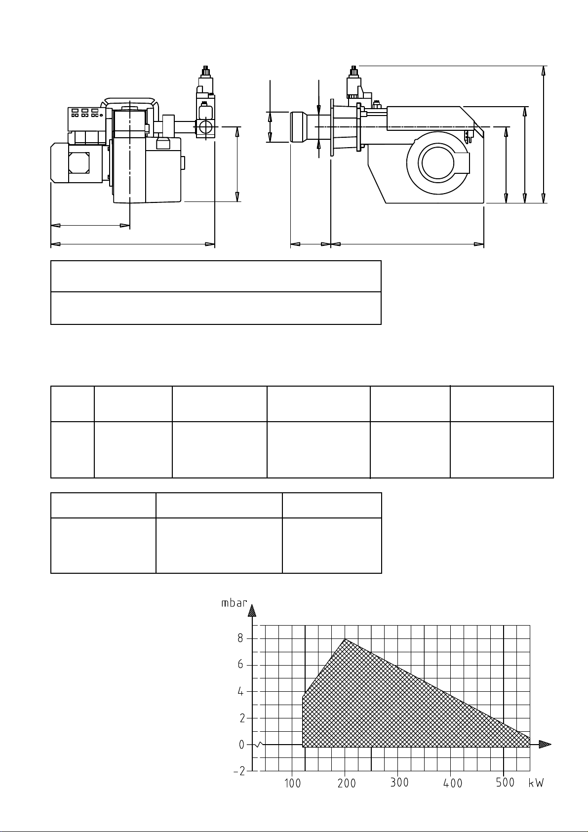
CAPACITYCHARTACCORDINGTO
EN 676
Type Capacity Gas volume at a min. Gas volume at a max Max. inlet Rated inlet pressure
kW output Nm3/h 1) output Nm3/h 1) pressure mbar mbar
Natural gas/LPG Natural gas LPG Natural gas LPG Natural gas LPG
450 120-550 12 4,6 55 21 360 40 30-50
2) Town gas 2) Town gas 2) Town gas 2) Town gas
OUTRANGE
TECHNICAL DATA
Type designation BG 450
DIMENSIONS
1) Calorific value:
Natural gas 10 kWh/Nm3
LPG 26 kWh/Nm3m3
2) Dimension and capacity depen-
ding on gas quality and available
inlet pressure
Length of burner Flange
tube Measure A
Standard 256 226
Long design 356 326
The above dimensions are max. measurements. Depending on the components
used, the measurements may vary.
640
262
A 538
252
ø160
ø130
500
328
252
172 215 50 00-01

TECHNICAL DATA
DIMENSIONSOFFLANGE
172 215 19 00-01
14
(ø210)ø254-280
ø163
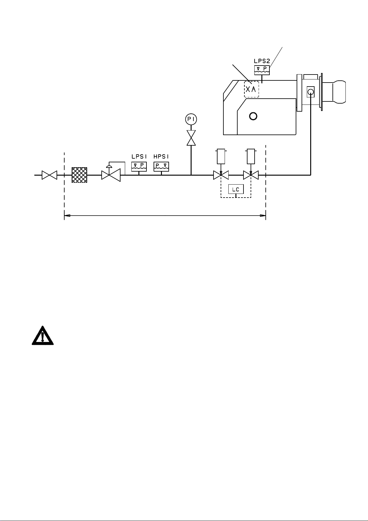
SKELETON DIAGRAMS
1. Ball valve
2. Filter
3. Governor
4. Pressure gauge with shut-off cock
5a. Gas pressure switch, mini
5b. Gas pressure switch, maxi
6a. Main valve.
7
123
5a 5b
4
6b 6a
10
Incorporated in the MultiBloc
9
6b. Safety valve
1) 7. Valve proving system
9. Air pressure switch
10. Gas burner control
Pos. 5b, 7: Components not required
according to EN 676.
1) Required over 1200 kW according
to EN 676.
172 415 08 03-01
When Bio gas is used, Bentone shall always be contacted.
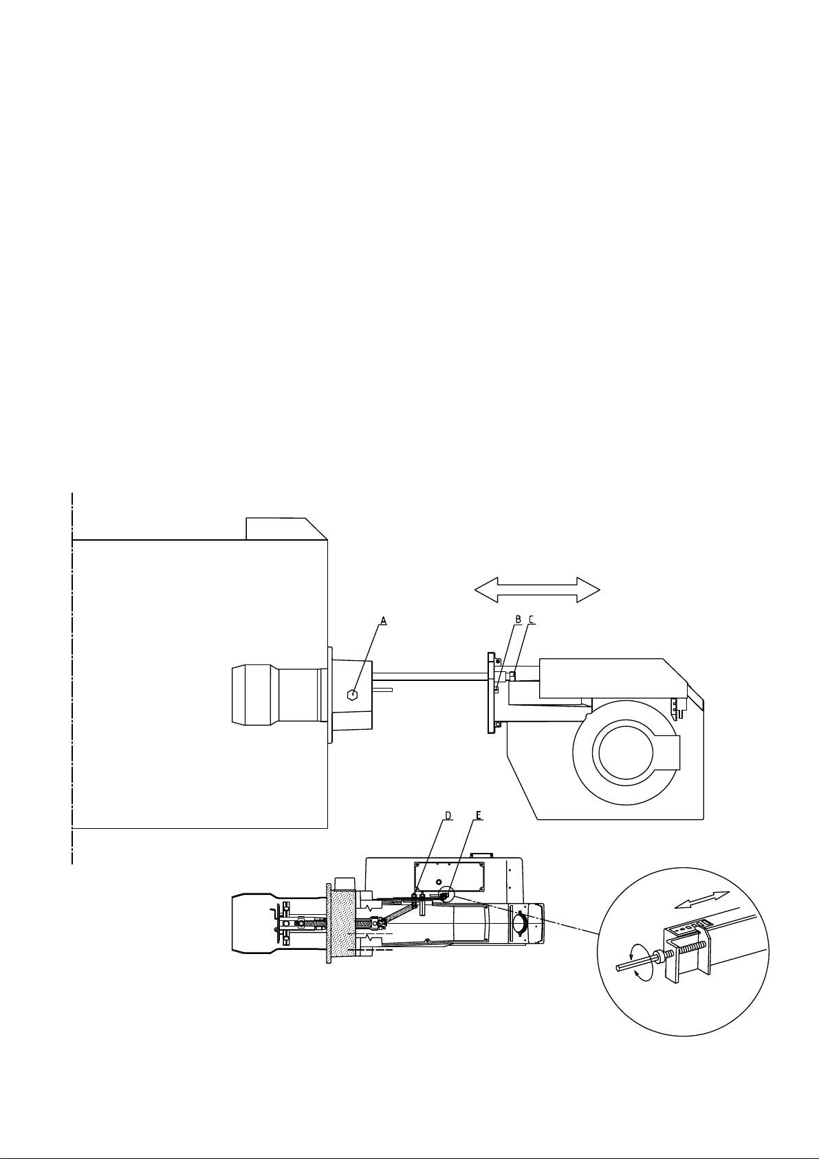
MOUNTING OF THE BURNER
172 205 20 01-01
Fit the burner to the boiler by means of
4 bolts M12. For flange and bolt dimen-
sions see technical data.
If for some reason you want to sepa-
rate the burner from the gas flange with
burner head and valve package you
can do so.
DO LIKE THIS:
- Remove the cover of the fan hou-
sing.
- Loosen the nut D of the gas assem-
bly package.
- Loosen the electric cables to the
valve package.
- Loosen the screws B on both sides.
- Loosen the stop bolt C on the pull
rods.
- Loosen the ignition cable and the
ionisation cable from the gas ass-
embly.
- Pull out the burner on the pull rods
and put it in a suitable place.
When the burner head and the gas
flange have been fitted to the boiler it is
easy to lift up the burner to where it
belongs.
INSPECTIONOFGASASSEMBLY
If the gas assembly needs to be in-
spected the pull rods are very useful.
DO LIKE THIS:
- Remove the cover of the fan hous-
ing.
- Loosen the nut D of the gas assem-
bly package.
- Loosen ignition cable and ionisa-
tion cable of gas assembly.
- Loosen the screw A on both sides.
- Pull out the burner on the pull rods.
- Loosen the screws B on the gas
flange.
- Withdraw the gas assembly.
Ensure that the O-ring between the
gas assembly and the gas flange will
be in the correct position when the gas
assembly is fitted again.
ADJUSTMENT OF THE POSITION
OF THE SHROUDED DISC IN THE
BLASTTUBE
Sometimes it is necessary to adjust
the position of the shrouded disc in the
blast tube. This can be done with the
screw E (can be adjusted when the
burner is in operation). If you turn the
screw to the left the shrouded disc will
move forward (+), to the right it will
move backward.
SERVICEPOSITION
NOTE!
For maintenance of the brake plate,
nozzles, electrodes etc, when using a
long design of the burner tube, you
have to removethenozzleassembly
fromtheconnectingpipeandmove
the assembly backwards in the fan
housing (from the boiler).

MEASURES AND CHECKS BEFORE START-UP, 1-STAGE BURNER
GENERALRULES
Care should be taken by the installer to
ensure that no electrical cables or fuel/
gas pipes are trapped or damaged
during installation or service/
maintenance.
INNERASSEMBLY
Ensure that the ignition and ionisation
electrodes are correctly adjusted. The
sketch shows the correct measure-
ments.
GASQUALITY
Ensure that the burner head is meant
for the gas quality to be used (see fig.).
VENTING
The gas line is vented by loosening the
screw on the test nipple for the inlet
pressure. Connect a plastic hose and
conduct the gas into the open. After
having vented the gas line tighten the
screw again.
LEAKAGECONTROL
When making a leakage control of the
gas supply system the solenoid valve
should be closed. Connect a pressure
gauge to the test nipple Pa, see fig.
The test pressure in the system should
be 1,5x max. inlet pressure or min.
150 mbar. If any leakage, locate the
source by means of soapy water or a
leak location spray. After tightening
repeat the test.
ELECTRICFUNCTIONTEST:
Ensure that phase and neutral are not
reversed. The gas shut-off cock should
be closed.To prevent the gas pressure
switch from locking out it should be
linked temporarily.
After the main switch has been swit-
ched on and the thermostats have
been adjusted the pre-purging period
begins (30-35sec.). At the end of this
period the pre-ignition period starts
(0,5-2,5 sec. dependent on the design
of the gas control). The gas valve is
energized and opens and flame is
established. At the end of the safety
time (2-3 sec.) the gas control locks
out. The solenoid valve and the motor
will be "dead". Remove the link from
the gas pressure switch after the test
is finished.
172 205 33 07-01
LEAKAGE CONTROL
NOTE! APPLIES ONLY TO GAS
BURNERCONTROLLFL1.
When using LPG (Propane) the burner
should be connected for post-purge.
Move connection to terminal 6 to ter-
minal 7 in the base of LFL1.
MEASURES AND CHECKS BEFORE START-UP
INNER ASSEMBLY
Town gas
INNER ASSEMBLY
Natural gas, LPG
INNER ASSEMBLY
Biogas ((UV-detector)
172 205 18 97-01
Propan Naturgas

172 205 16 98-01
DETERMINATION OF GAS VOLUME FOR THE INSTALLATION
V = Gas volume Nm3/h
Q = Boiler output 120 kW
Hu= Calorific value of the gas A. 37 144 kJ/Nm3, B. 10.3 kWh/Nm3
η= Expected efficiency 90%
Ex. A
Ex. B
If the barometer height, pressure and temperature of the gas deviate very much from the normal values this must be taken
into account as follows:
f=
t = Temperature of the gas at the gas meter (15°C)
B = Barometer height (945 mbar)
Pu= Pressure of the gas at the gas meter (15,0 mbar)
f=
f≈1.11
The gas volume read on the gas meter actually reads 1,11 .12,9 = 14,4 m3/h.
Net calorific value
Gas quality kWh/Nm3kJ/Nm3kcal/Nm3
Natural gas 10.3 37 144 8 865
Propane 26.0 93 647 22 350
Butane 34.3 123 571 29 492
Town gas 4.9 17 653 4 213
Bio gas 7.0 25 219 6 019
Specifications on natural gas, town
gas and bio gas vary. For more exact
information please contact the gas
distributor.
EXAMPLE HOW TO CALCULATE THE GAS VOLUME (NATURAL GAS)
273+15
273 .1013,25
945+15
V=120
10,3 · 0,90 ≈12,9 Nm3/h
B+Pu
273+t
273 .1013,25
120 .3 600
37 144 .0,90
V=Q .3 600
Hu · η =≈12,9 Nm3/h

172 425 99 16-01
ELECTRIC EQUIPMENT
Gas burner control: LME11/LME21
Wiring diagram
1(3)
1N ~ 50/60 Hz 230 V
List of components
A1 Gas burner control
B1 Ionization electrode
F1 Fuse
H1 Lamp, low capacity
H3 Alarm signal 220 V
K1 Motor contactor
M1 Burner motor
P1 Time meter, total operating time
S1 Operating switch
S3 Control thermostat
S4 Temperature limiter
S5 Micro switch for hinged door
S7 Main switch
S8 Air pressure swith
S9 Gas pressure switch
T1 Ignition transformer
X1 Connection terminal board
X2 Earth terminal
X3 Plug-in contact, burner
X4 Plug-in contact, boiler
Y1 Gas solenoid valve
Mains connection in accordance with
local regulations.
If there is no Plug-in
contact (X4,X6) on
the boiler, connect
to the contact
enclosed. Max loading K1
Connection A1,A2 / 95, 96 / 97, 98
Max 0,2A/15W

172 425 99 16-01
2(3)
ELECTRIC EQUIPMENT
Control diagnosis under fault conditions and lockout indication
Gas burner control: LME....
Colour codes
Diagnostics alarm trigger
The red alarm signal lamp lights continuously after the alarm is disconnected.
Limit on start attempts
or goes out during operation. LME 11 … permits a maximum of three start attempts if
the start cycle is uninterrupted.
Continuous
Off
Red
Yellow
Green
Colour code table for multi-coloured signal lamps (Light diodes)
Status Colour codes Colours
Waiting time «tw», other waiting times ○………………… Off
Ignition phase, ignition checked •○ •○ •○ •○ •○ • Flashing yellow
Normal operation Green
Flashing green
Green-Red
Undervoltage Yellow-Red
Disruption, alarm Red
Flashing code for fault codes Flashing red
Interface diagnostics
AL
FS
Flash code Pause Flash code
Approx. 3 s
lights red Press the reset
button > 3 s
172 425 99 16-01
3(3)
ELECTRIC EQUIPMENT
Control diagnosis under fault conditions and lockout indication
Gas burner control: LME...
During alarm trigger diagnostics, control outputs are to be disconnected from all
power.
– The burner is disconnected
– Exception, the «AL» alarm signal at connection block 10
– The burner is only to be reconnected after it is reset
– Press the reset button 0.5...3 s
Interface diagnostics
To switch to interface mode, hold the reset button depressed for more than 3 s. To
unit is in the alarm mode, it is reset by pressing the reset button 0.5...3 s.
Alarm control table
on signal lamp
(LED)
Possible causes
Flashing 2 x
••
•
–
– Defective or obscured fuel valves
– Poor burner installation
– Defective ignition unit
Flashing 3 x
•••
«LP» defective
– No air monitor signal after «t10»
– «LP» is welded in the open position
Flashing 4 x
••••
Flashing 5 x
•••••
Time out «LP»
– «LP» is welded in the closed position
Flashing 6 x
••••••
Free
Flashing 7 x
•••••••
– Poor burner installation
– Defective or obscured fuel valves
–
Flashing 8 x
••••••••
Free
Flashing 9 x
•••••••••
Free
Flashing 10 x
••••••••••
Connections fault or internal fault,
outgoing contacts or other fault
Flashing 14 x
••••••••••
••••
CPI contact not closed

ADJUSTMENT OF MULTI-BLOC, MB-DLE 405-420
Max. inlet pressure: 360 mbar.
Adjustable governor pressure:
405 - 412 S50 = 4 - 50 mbar
415 - 420 S20 = 4 - 20 mbar
415 - 420 S50 = 20 - 50 mbar
Solenoid valve: Slow opening valves
with adjustable start load and max.
flow.
1. Protective cover start load ad-
justment
2. Hydralic damping
3. Fixing screw
4. Test nipple (inlet pressure)
5. Test nipple (pressure after go-
vernor)
6. Test nipple (pressure in inner
assembly)
7. Governor
8. Filter
9. Gas pressure switch
10. Solenoid valve
FLOWADJUSTMENT
Loosen the fixing screw a. Turn the
hydraulic device b:
to the right = the gas flow is reduced
to the left = the gas flow is increased
Do not forget to tighten the fixing screw
again.
The flow adjustment can also be made
by means of the governor. Adjust the
outlet pressure to a value giving the
desired gas flow on the fully open
valve. At small capacities (gas flows) it
is also necessary to adjust as abore.
ADJUSTMENT OF GOVERNOR
Adjust outlet pressure from governor
by means of a screw . Min. and max.
outlet pressures corresponds to appr.
60 turns of the spring. It is not possible
to change pressure springs in order to
change the outlet pressure.
Turn to the right = the outlet pressure
is increased
Turn to the left = the outlet pressure is
reduced
ADJUSTMENT OF START GAS
FLOW
Remove the protective cover c.
Turn the adjustment knob d (use the
protective cover as a tool) to the desi-
red start gas flow.
Turn to the right = the start gas flow is
reduced
Turn to the left = the start gas flow is
increased
ADJUSTMENT OF START GAS
FLOW
ADJUSTMENT OF GOVERNOR
FLOWADJUSTMENT
172 505 02 97-02

GENERAL INSTRUCTIONS
ADJUSTMENT OF BURNER
The burner is from the factory pre-set
to an average value that must then be
adjusted to the boiler in question.
All burner adjustments must be made in
accordance with boiler manu-facturers
instructions.These must include the
checking of flue gas temperatures,
average water temperature and CO2or
O2concentration.
GENERALINSTRUCTIONS
The installation of the gas burner must
be carried out in accordance with
current regulations and standards. The
installers of gas burners should there-
fore be acquainted with all regulations
and ensure that the installation comp-
lies with the requirements. The instal-
lation,mountingandadjustment should
be made with the greatest care and
only the correct gas should be used.
OPERATINGINSTRUCTIONS
The operating instructions accompanying
the burner should be left in a prominent
position in the boiler room.
INSTRUCTIONS
The user should be thoroughly in-
structed in the function of the gas
burner and the whole installation. The
supplier must instruct the user.
INSPECTIONANDMAINTENANCE
Daily inspection is advisable.
START UP
After the burner has been fitted to the
boiler and the electric connection, the
leakage control, the venting and the
electric function test have been car-
ried out, the burner will be ready for
start-up.
Howerer, study the sections dealing
with adjustments of multi-bloc, com-
bustion air and combustion head.
Open the ball valve and switch on the
main switch. If the burner starts the
actual adjustment can be made.
ADJUSTMENT OF BURNER HEAD
The burner is equipped with an ad-
justment device changing the position
of the brake plate in the burner head.
This is used to adjust the correct pres-
sure drop over the combustion device
in order to obtain a good pulsation free
combustion.
Which position to use depends on
input and overpressure in the boiler. 172 305 28 97-01
A general rule is that the lower capa-
city the smaller the opening between
brake plate and combustion device.
COMMISSIONINGOFINSTALLA-
TION
Control of the combustion. The com-
bustion quality is checked by means
of a flue gas analysis device. Adjust
the burner to appr. 20% excess air in
accordance with the table. Check the
flue gas temperature. Calculate the
efficiency. Check also the actual gas
volume on the gas meter so that the
correct input is achieved.
SERVICE
Service should only be carried out by
qualified personnel. Replacement
parts should be of the same make
and approved by the same authoriti-
es as the original. If the burner is
converted to fire another gas quality it
must be re-commissioned. If town
gas is to be fired the combustion head
must be converted and the gas train
adjusted to suit (e.g.a larger gas ar-
mature or a different spring in the
governor may be required).
Gas quality CO2%0
2% max. CO2%
lambda 1,2
Natural gas 10,0 3,5 11,9
LPG 11,5 3,5 13,9

172 305 25 00-01
FLAMEMONITORINGANDMEASU-
REMENTOFIONISATIONCURRENT
The burner is monitored according to
the ionisation principle. Check the io-
nisation current on start-up and on
each service call.
The reason for a low ionisation current
may be leaking currents, bad connec-
tion to earth, dirt or a faulty position of
the flame electrode in the burner head.
Sometimes also a faulty gas/air mixtu-
re may cause too weak a ionisation
current.
The ionisation current is measured by
means of a microampere meter (μA)
connected in series with the flame
electrode and the gas burner control.
Connect the μA-meter, see figure.
Min. required ionisation current ac-
cording to table. In practice this cur-
rent must be considerably higher, pre-
ferably more than 10 μA. All the gas
burners are equipped with a ionisation
cable that can be slit which facilitates
the connection of the μA-device.
GAS PRESSURE SWITCHES:
Adjustment range:
2,5-50 mbar GW 50
5-150 mbar GW 150
ADJUSTMENTOFMIN.GASPRES-
SURE SWITCH
The min. pressure switch should react
if the gas pressure is too low and
prevent the burner from starting. Too
low a gas pressure during operation
should stop the burner. The burner
may start again when the rated gas
pressure has been reached.
Remove the protective cover. Connect
a pressure gauge for measuring the
rated pressure. Decide on pressure at
which the gas switch should switch off.
Set this pressure by means of the
valve. Carefully turn the knob (see
figure) until the gas pressure switch
switches off. The value shown on the
scale should then approximately cor-
respond with the value shown on the
pressure gauge. Tolerance on scale
appr. ± 15 %. Open the ball valve.
GENERAL INSTRUCTION
ADJUSTEMNTOFMAX.GASPRES-
SURE SWITCH
The burner is equipped with a max. gas
pressure switch only on request. It
should stop the burner if the gas pres-
sure exceeds the set value. The burner
can then only be re-started manually
(gas burner control or overpressure
switch).
Remove the protective cover. Connect
a pressure gauge for measuring the
rated gas pressure. Decide on pres-
sure at which the gas pressure switch
should switch off. Turn the adjustment
knob to this value. Tolerance on the
scale ±15%.
ADJUSTMENT OF AIR PRESSURE
SWITCH
The air presure switch should stop the
burner if the air volume is reduced.
The air proving device shall be adjus-
ted in such a way that if there is
insufficient air supply at the highest or
lowest burner operating stage, the
device operates before the supervised
pressure is less than 80% of the pres-
sure at the controlled stage and the CO
content of the combustion products
exceeds 1% by volume.
AIR PRESSURE SWITCH:
Adjustment range ca:
1-10 mbar LGW 10
2,5-50 mbar LGW 50
FLAMEMONITORING
GAS PRESSURE SWITCH, AIR
PRESSURESWITCH
Gas control Connection to terminal Min. ionisation
in gas control current required
LMG 1 2 μA
LGB 1 10 μA
LFL 24 10 μA
MMI 810 2 5 μA
TMG 740-3 1 5 μA

HANDING OVER OF THE INSTALLATION
172 305 17 93-01
- Make repeated start attempts to
ensure that the adjustments func-
tion.
- Close the ball valve during opera-
tion to check that the gas switch
switches off at the set value.
- Remove the hose for the air pressu-
re switch to check that the burner
locks out.
- Check that all protective covers
and measurement nipples are
mounted and fastened.
- Fill out necessary test reports.
- Instruct the persons in charge of the
operation on the service and main-
tenance of the installation and what
to do should any troubles occur.
-Inspection and service must only
be carried out by authorized
people.
FAULT LOCATION, FUNCTIONAL
TROUBLES
Trouble free operation is dependent on
three factors: electricity, gas and air
supply. Should there be any changes
in the ratio between these three factors
there is a risk of break downs. It has
been proved that most break downs are
caused by simple faults. Before calling
the service engineer, the following
should therefore be checked:
- Is the gas cock open?
- Are all fuses in order and the cur-
rent switched on?
- Are the thermostats correctly set?
- Are pressostats, overheating pro-
tection etc. in operating position
and not locked-out?
- Is the gas pressure sufficient?
- Is the gas burner control in start
position?
- Has the gas control or the motor
protector locked out? - Reset.
- Is the circulation pump in opera-
tion?
- Is there a supply of fresh air to the
installation?
If integral components are of a diffe-
rent make from what is stated in this
manual, see the enclosed loose-leaf.

170 091 16 97-01
Gas burner
FAULTLOCATIONGUIDE
The basis for trouble free operation can only be ensured
by the correct combined effect of the three factors:
electricity, gas flow and combustion air. Should any of
these factors change troubles may arise.
It has been proved that many troubles have rather simple
causes. Before calling the serviceman the following
checks should be made:
1. Are the gas cocks of the installation open?
2. Are the fuses in order and the current switched on?
3. Are the controls (room thermostat, boiler thermostat
etc.) correctly adjusted?
4. Is the gas pressure to the burner sufficient?
5. Is the gas relay of the burner ready for start and not
locked out?
6. Is the air supply to the burner sufficient?
To facilitate fault location we have drawn up a scheme
showing the most frequent faults in a gas burner instal-
lation and the remedies.
CAUSE
The burner does not start
No gas
No voltage
The burner motor fails to start
The gas relay is defective
Burnermotorisrunningbutnoignitionafterthepre-
purge time has elapsed
No voltage on the terminals
The ignition electrodes in contact with each other or with
earth
The porcelain of the electrodes is broken
Check that all gas cocks are open.
Check fuses, thermostats and electrical connections.
The thermal protection has locked out. Motor defective.
Replace
Check the contact. Replace faulty relay
Adjust
Replace the electrodes
REMEDY
1(4)

REMEDY
Improve the contact
Replace
Replace the transformer
Change
Replace
Replace coil or the whole valve if necessary.
Check the contact
Test the adjustment and the function of the air pressure
switch.
Reduce or increase the gas supply, reduce the quantity
of air.
Replace
Check the adjustment and readjust.
Adjust the ionisation electrode and the UV-cell, examine
cables and connections.
Replace the relay
CAUSE
The cable shoes have bad contact
The ignition cables are damaged
The ignition transformer is damaged, no voltage on the
secondary side
The ignition cable and the ionisation cable have been
transposed.
Noflameestablishmentinspiteofatroublefreestart
The gas solenoid valve defective
The gas solenoid valve does not open in spite of its
obtaining voltage
No voltage to the solenoid valve
No electrical connection through the air pressure switch
The starting load is not correctly adjusted
Gas relay defective
Air pressure switch incorrectly adjusted or defective
No reponse as the cams of the servomotor are not
correctly adjusted or out of position.
Theburnerlocksoutafterthesafetytimehaselapsed
inspiteofflameestablishment
No ionisation current or the UV-cell in wrong position
The supervision part of the gas relay is defective
2(4)
Table of contents
Other Enertech Furnace manuals

Popular Furnace manuals by other brands


ICP
ICP NTC6/GNE Series installation instructions

International Comfort Product
International Comfort Product WFEU Series installation instructions

Lennox
Lennox ML193UH instruction manual

Goodman
Goodman MH8 installation instructions

Bryant
Bryant 312A Installation, start-up, operating and service and maintenance instructions

Unitary products group
Unitary products group DLAS Use and care instruction