Entec EVRC2A-N6-NT User manual

RECLOSER CONTROL EVRC2A-N6,NT
USER’S MANUAL
ENTEC
ELECTRIC & ELECTRONIC CO., LTD
ENTEC
Copyright © 2002 by ENTEC ELECTRIC & ELECTRONIC CO., LTD all right reserved. Forerunner Distribution & Automation
Release Date: Feb. 2013 / Manual Revision: 7.13


RECLOSER CONTROL EVRC2A-N6,NT http://www.entecene.co.kr
i
ENHANCED
TECHNOLOGY
Release Note:
[Oct. 2006] Ver4.00
1. Add explanations for new additional function below
-Support ETHERNET Port(Port4) for EVRC2A
-Support IEC60870-5-104 Protocol Communication (add the setup menu)
[Sept. 2007] Ver4.10
1. Add explanations for new additional function below
-Dialing Modem Support(add the setup menu)
[Sept. 2009] Ver4.12
1. Add explanations for new additional function below
-Support IEC60870-5-101 Protocol Communication (add the setup menu)
-Support Overfrequency Protection Element (add the setup menu)
[Jan. 2010] Ver5.00
After the Ver5.00, the manual is applied to the
“EVRC2A-N(Network type)”
.
1. Support “ETIMS(ENTEC Integration Management Software)” function(add the setup menu).
This function is used to interface with ETIMS over Ethernet port.
2. Separate “Communication” setting into “Protocol” and “Port” settings.
3. Describe elements consisting of “Protection” section in order of the menu shown in LCD.
4. Add “CLOSE Function at Normal Frequency restored” in Frequency element.
5. Add the description related with “STATUS” menu omitted in the previous version.
6. Add the description related with “MAINTENANCE” menu omitted in the previous version.
7. Add “Fault Trip(option)” in “EVENT RECORDER” menu.
[Jul. 2010] Ver5.10
1. Add contents of RVD(Resistance Voltage Divider), one of Voltage Divider Inputs.
[Sep. 2010] Ver5.11
1. Add “6.10. Set Group Change”.

RECLOSER CONTROL EVRC2A-N6,NT http://www.entecene.co.kr
ii ENHANCED
TECHNOLOGY
[Mar. 2011] Ver5.20
1. Add “Loss of Phase” in “PROTECTION” menu according to an additional function (option),
“Loss of Phase”.
2. Add “Supply Outage Measurement” as an additional function in menu.
-Add “S-Outage” and “S-O Dura” set-up in “RELAY SETUP/ EVENT RECORDER” menu.
-Add “S-Outage Count” and “S-Outage Event” set-up in “RELAY SETUP/ CLEAR SAVED
DATA” menu.
-Add “S-OUTAGE COUNTER” in “MAINTENANCE” menu.
-Add “SUPPLY OUTAGE” in “EVENT RECORDER” menu.
[Jan. 2012] Ver6.00
After the Ver6.00, the manual is applied to the
“EVRC2A-N6(Network type)”
.
[Jan. 2012] Ver6.00
1. Change the terms related with battery testing.
[Feb. 2012] Ver6.01
1. Add “Power Quality” set-up in “SYSTEM SETUP” menu.
2. Change “Supply Outage” to “Power Quality” in some menus.
-Change “S-Outage Counter” to “Power Quality” in “MAINTENANCE” menu.
-Change “Supply Outage” to “Power Quality” in “EVENT RECORDER” menu.
-Change “S-Outage Count” and “S-Outage Event” to “P-Quality Count” and “P-Quality” in
“RELAY SETUP/ CLEAR SAVED DATA” menu.
3. Add “HARMONICS” in “MAIN MENU/6.METERING” menu.
[Jun. 2012] Ver6.02
Changed the manual based on EVRC2A-N6 firmware V6.12 upgrading.
1. Section to be rectified in the manual as a result of adding measuring function of
voltage/current unbalance.
-Change “METERING” in “1.2. Summary of Features”.
-Change “Table 2-1. Metering Accuracy” in “2.3. Metering Accuracy”.
-Add “10.1.9. Unbalance”.
-Change “Table 10-1. Metering Accuracy” in “10.2. Accuracy”.
2. Section to be rectified in the manual as a result of adding detection function of
voltage/current unbalance.
-Change “MONITORING” in “1.2. Summary of Features”.

RECLOSER CONTROL EVRC2A-N6,NT http://www.entecene.co.kr
iii
ENHANCED
TECHNOLOGY
-Change “RECORDER” in “1.2. Summary of Features”.
-Add “Power Quality” in “2.5. Monitoring”.
-Change “SYSTEM EVENT RECORDER”, “POWER QUALITY EVENT RECORDER”,
“COUNTER” in “2.6. Recorder”.
-Change “Figure 3-12. Menu Structure Tree” in “3.2.1. Main Menu Summary”.
-Add settings for Unbalance in “6.10. Power Quality”.
-Add Unbalance Counter in “11.4. Power Quality”.
-Change “12.2. System Event Recorder”.
-Change “12.6. Power Quality Event Recorder”.
3. Section to be rectified in the manual as a result of adding “Daily Max I” and “Daily Energy”
settings.
-Change “5.2.5. EVENT&ETC”.
4. Section to be rectified in the manual as a result of changed range of reclose interval 1.
-Change “Reclose interval 1” in “2.4. Protection Elements/ Reclose Control”.
-Change “Range of Reclose 1” in “7.1. Reclose(79)”.
[Aug. 2012] Ver7.00
Changed the manual based on EVRC2A_N6 firmware V6.15 upgrading.
1. Change “5.3. Clock”.
2. Change “5.8. Time Set & Display Type”.
-Add “Set Type”, “GMT Sign”, “GMT Hour”, “GMT Min” and “Evt Send Type” set-up in
“RELAY SETUP/ TIME SET & DIS TYPE” menu.
3. Change “SEF Pickup Current Setup” in “7.4. Sensitive Earth Fault (SEF)”.
4. Change “9.3. Clock”.
5. Change “10.1.4. Synchro Voltage”.
6. Change “Table 14-1. Warning Events” in “14.1. Warning Events”.
[Nov. 2012] Ver7.10
1. Changed the manual based on EVRC2A_NT firmware V7.04 upgrading.
-Change “5.2.2.1. DNP 3.0 Protocol – Option” : Add “Time Req(m)” set-up in
“COMMUNICATION / PROTOCOL SETUP / DNP1 and DNP2” menu.
-Change “5.2.3.1. PORT2-RS232” : Add “Parity Bit”, “Data Bit” and “Stop Bit” set-up in
“COMMUNICATION/ PORT SETUP/ PORT1-RS232” menu.
-Change “5.2.5. EVENT&ETC” : Add “Time Syn’ Ref” and “Evt Time Type” set-up in
“COMMUNICATION/ EVENT&ETC” menu.
-Change “5.8. Time Set & Display Type – Option” : Add “Time Syn’ Ref” set-up in “RELAY

RECLOSER CONTROL EVRC2A-N6,NT http://www.entecene.co.kr
iv ENHANCED
TECHNOLOGY
SETUP / TIME SET&DIS TYPE” menu.
2. Changed the manual based on EVRC2A_NT firmware V7.06 upgrading.
-Change “5.2.2.2. IEC60870-5-101 Protocol – Option” : Add the setting items in
“COMMUNICATION / PROTOCOL SETUP / IEC60870-5-101” menu.
-Change “5.2.2.3. IEC60870-5-104 Protocol – Option” : Add the setting items in
“COMMUNICATION / PROTOCOL SETUP / IEC60870-5-104” menu.
-Change “6.3. Line VL Sensing” : Add “Install Type” set-up in “SYSTEM SETUP / LINE
VL SENSING” menu.
3. Change the description for “SKIP at Fault” and “Fault ‘I’ Evt” setting in “5.2.5.
EVENT&ETC”.
4. Add the Note in “6.4. System Power”.
[Nov. 2012] Ver7.12
1. Changed the manual based on EVRC2A_NT firmware V7.07 upgrading : Delete “Tx Delay”
set-up in “COMMUNICATION / PROTOCOL SETUP / DNP1 and DNP2” menu.
-Change the description for “Tx Delay” setting in “5.2.2.1. DNP3.0 Protocol – Option”.
2. Change the description for “TX Post Delay” and “TX Pre Delay” in “5.2.3.1. PORT2 –
RS232”.
3. Change the setting examples of “Use of VD(CVD or RVD)” in “6.2. Line VS Sensing / 6.2.3.
Setting Examples”.
[Dec. 2012] Ver7.12
1. Add the Note in “5.8. Time Set & Display Type – Option”.
2. Add the Note in “5.2.5. EVENT&ETC”.
3. Change “Figure 7-33. Non Standard Curves (11, 13, 14, 15, 16, 17, 18)” in “7.18. Time
Overcurrent Curves”.
[Feb. 2013] Ver7.13
1. Add the Notes in “2.4. Protection Elements”.
2. Add the Note of “SEF Pickup Current Setup” in “7.4. Sensitive Earth Fault (SEF)”.
3. Add the Note of “SEF” setting in “7.12.3. Cold Load Pickup Setup”.
4. Add the Note in “9.4. Control Type”.

RECLOSER CONTROL EVRC2A-N6,NT http://www.entecene.co.kr
v
ENHANCED
TECHNOLOGY
TABLE OF CONTENTS
1. INTRODUCTION ........................................................................................................... 1
1.1. Description .......................................................................................................................... 1
1.2. Summary of Features .......................................................................................................... 2
2. TECHNICAL SPECIFICATIONS................................................................................. 5
2.1. Inputs and Outputs .............................................................................................................. 5
2.2. Type Withstand Tests........................................................................................................... 8
2.3. Metering Accuracy .............................................................................................................. 9
2.4. Protection Elements........................................................................................................... 11
2.5. Monitoring......................................................................................................................... 16
2.6. Recorder ............................................................................................................................ 19
2.7. Communications................................................................................................................ 22
3. USER INTERFACE PANEL ........................................................................................ 23
3.1. Construction ...................................................................................................................... 24
3.2. LCD Display ..................................................................................................................... 33
3.3. Using the LCD Menu ........................................................................................................ 37
4. SELECT SETBANK ..................................................................................................... 40
5. RELAY SETUP.............................................................................................................. 41
5.1. Passcode ............................................................................................................................ 41
5.2. Communication ................................................................................................................. 42
5.3. Clock ................................................................................................................................. 76
5.4. Event Recorder.................................................................................................................. 78
5.5. Clear Saved Data............................................................................................................... 79
5.6. Factory Debug................................................................................................................... 79
5.7. Gas Sensor Type................................................................................................................ 80
5.8. Time Set & Display Type – Option ................................................................................... 80
6. SYSTEM SETUP........................................................................................................... 82
6.1. Current Sensing................................................................................................................. 82
6.2. Line VS Sensing................................................................................................................ 84
6.3. Line VL Sensing................................................................................................................ 86

RECLOSER CONTROL EVRC2A-N6,NT http://www.entecene.co.kr
vi ENHANCED
TECHNOLOGY
6.4. System Power .................................................................................................................... 88
6.5. Panel Sleep Time............................................................................................................... 91
6.6. Opto Input Set - Option ..................................................................................................... 91
6.7. Output Relay Set - Option ................................................................................................. 93
6.8. Loop Control - Option....................................................................................................... 96
6.9. Set Group Change - Option ............................................................................................. 115
6.10. Power Quality - Option ................................................................................................. 116
7. PROTECTION ............................................................................................................ 120
7.1. Reclose (79)..................................................................................................................... 122
7.2. Phase (Fast/Delay) Time Overcurrents (51P).................................................................. 128
7.3. Ground (Fast/Delay) Time Overcurrent (51G)................................................................ 132
7.4. Sensitive Earth Fault (SEF)............................................................................................. 136
7.5. Negative Sequence (Fast/Delay) Time Overcurrent (46)
.......................................................... 138
7.6. Phase High Current Trip (50P-1)..................................................................................... 142
7.7. Ground High Current Trip (50G-1) ................................................................................. 144
7.8. Negative Sequence High Current Trip (46(50)-1)........................................................... 146
7.9. Phase High Current Lockout (50P-2).............................................................................. 148
7.10. Ground High Current Lockout (50G-2) ........................................................................ 150
7.11. Negative Sequence High Current Lockout (46(50)-2)
............................................................ 152
7.12. Cold Load Pickup.......................................................................................................... 154
7.13. Directional Controls (67)............................................................................................... 162
7.14. Undervoltage (27).......................................................................................................... 170
7.15. Overvoltage (59)............................................................................................................ 172
7.16. Frequency(81) ............................................................................................................... 174
7.17. Other Element................................................................................................................ 177
7.18. Time Overcurrent Curves .............................................................................................. 180
7.19. Loss of Phase - Option .................................................................................................. 207
8. MONITORING ........................................................................................................... 208
8.1. Demand ........................................................................................................................... 208
8.2. Synchronism Check (25)................................................................................................. 211
8.3. Trip Counter .................................................................................................................... 213
8.4. Recloser Wear.................................................................................................................. 215
8.5. Battery Test...................................................................................................................... 217
8.6. Fault Locator ................................................................................................................... 218
8.7. Gas Low Lock – Option .................................................................................................. 220

RECLOSER CONTROL EVRC2A-N6,NT http://www.entecene.co.kr
vii
ENHANCED
TECHNOLOGY
8.8. EXT’ Trip & Lock – Option............................................................................................ 220
8.9. Live Load Block – Option............................................................................................... 221
9. STATUS ........................................................................................................................ 222
9.1. OPTO Inputs ................................................................................................................... 222
9.2. Relay Outputs.................................................................................................................. 222
9.3. Clock ............................................................................................................................... 223
9.4. Control Type.................................................................................................................... 224
10. METERING............................................................................................................... 225
10.1. Metering Elements ........................................................................................................ 226
10.2. Accuracy........................................................................................................................ 235
11. MAINTENANCE....................................................................................................... 237
11.1. Counters......................................................................................................................... 237
11.2. Wear Monitor................................................................................................................. 237
11.3. Output Relay Test .......................................................................................................... 238
11.4. Power Quality - Option ................................................................................................. 239
12. EVENT RECORDER................................................................................................ 241
12.1. Waveform Capture ........................................................................................................ 241
12.2. System Event Recorder ................................................................................................. 245
12.3. Load Profile................................................................................................................... 247
12.4. Diagnostic Event Recorder............................................................................................ 250
12.5. Fault Trip Event Recorder - Option............................................................................... 252
12.6. Power Quality Event Recorder - Option ....................................................................... 254
13. INSTALLATION ....................................................................................................... 257
13.1. User Interface Door and Power Switch......................................................................... 257
13.2. Vent and Outer Cover .................................................................................................... 258
13.3. Dimensions and Mounting Plan .................................................................................... 259
13.4. Earth Wiring Diagram ................................................................................................... 261
13.5. Inner Structure............................................................................................................... 262
13.6. Mount Accessories Dimensions .................................................................................... 263
13.7. User-Available DC Power ............................................................................................. 264
13.8. Terminal Block and Fuses ............................................................................................. 265
13.9. EVRC2A Wiring Diagram – VD Type.......................................................................... 266
13.10. EVRC2A Wiring Diagram - VT Type ......................................................................... 267
13.11. Side Panel .................................................................................................................... 268

RECLOSER CONTROL EVRC2A-N6,NT http://www.entecene.co.kr
viii ENHANCED
TECHNOLOGY
13.12. Current Inputs Wiring Diagram................................................................................... 269
13.13. VD Wiring Diagram .................................................................................................... 270
13.14. VT Wiring Diagram..................................................................................................... 271
13.15. Current and Voltage Inputs Phase Rotation................................................................. 272
13.16. Control Cable Receptacle Pin Descriptions ................................................................ 273
13.17. Control Cable Assembling / De-assembling................................................................ 275
13.18. AC Power Receptacle Pin Descriptions ...................................................................... 275
13.19. AC Power Cable .......................................................................................................... 276
13.20. Fuses............................................................................................................................ 276
13.21. Battery and Control run time....................................................................................... 277
13.22. Charge Circuit ............................................................................................................. 278
13.23. Battery Change............................................................................................................ 278
13.24. Battery Protection........................................................................................................ 278
13.25. Communications.......................................................................................................... 279
13.26. Communication Cables ............................................................................................... 281
13.27. Hardware Block Diagram............................................................................................ 282
13.28. Recloser Trip and Close Circuits................................................................................. 283
13.29. Uninterruptible Power Supply for Trip & Close ......................................................... 284
13.30. Main Board.................................................................................................................. 285
13.31. Analog Board............................................................................................................... 286
13.32. Recloser EVR Wiring Diagram ................................................................................... 287
13.33. Recloser EPR Wiring Diagram.................................................................................... 288
13.34. Recloser Current Transformer (CT) ............................................................................ 289
13.35. Recloser Voltage Divider (VD) ................................................................................... 289
13.36. Recloser Pressure Sensor (Only EVR Type) ............................................................... 290
13.37. Recloser 52 contact and 69 contact ............................................................................. 292
13.38. Recloser Trip and Close Coil....................................................................................... 292
13.39. Recloser Test Kit ......................................................................................................... 293
14. MAINTANANCE ...................................................................................................... 294
14.1. Warning Events ............................................................................................................. 294
14.2. Malfunction Events ....................................................................................................... 296

RECLOSER CONTROL EVRC2A-N6,NT http://www.entecene.co.kr
1
ENHANCED
TECHNOLOGY
1. INTRODUCTION
1.1. Description
yEVRC2A with the microprocessor-based digital control technology is designed to provide
protective coordination and fault clearance of distribution systems for the continuous best
quality of electric service.
yRemote monitoring and control can be provided by RTU(Remote Terminal Unit - Option)
which fundamentally installed.
yIn order to perform the protection function, line voltage and current signal filtered with
analog filter and digital DFT full-cosin filter is used.
yEVRC2A provides protection, control, and monitoring functions with both local and remote.
It also displays the present trip/alarm conditions, and measured system parameters.
yRecording of past trip, alarm or control events, maximum demand levels, and energy
metering is also performed.
yUsers can operate Close and Trip, and also control EVRC2A with key buttons on the user
interface panel; Protection Enabled, Ground Enabled, SEF Enabled, Reclose Enabled,
Control Locked, Remote enabled, Alternate-settings, Program 1, Program 2, Hot line tag.
yUsers can manage the Recloser interface software using a portable PC for modification of
settings, acquisition of event data, and management of operation history.
yEVRC2A contains many T-C characteristic curves developed by IEEE C37.112, IEC255-3,
McGraw Edison, and KEPCO to provide fully protective coordination for the continuous
best quality of electric distribution. Users can select any time of current curve simply by
programming and modifying.

RECLOSER CONTROL EVRC2A-N6,NT http://www.entecene.co.kr
2ENHANCED
TECHNOLOGY
1.2. Summary of Features
PROTECTION
yPhase Instantaneous Over-current Element
yPhase Time Over-current Elements
yPhase Definite Time High Current Lockout Element
yGround Instantaneous Over-current Element
yGround Time Over-current Elements
yGround Definite Time High Current Lockout Element
ySensitive Earth Fault Elements
yNegative Instantaneous Over-current Element
yNegative Time Over-current Elements
yNegative Definite Time High Current Lockout Element
yPhase, Ground, Sensitive Earth and Negative Sequence Directional Control
yAutomatic Reclosing(Up To 4 Shots)
yCold Load Pickup with Voltage Control
ySequence Coordination Control
yTwo Under-voltage Elements
yTwo Over-voltage Elements
yUnder-frequency Element
yOver-frequency Element
yLoop Control - Option
yLoss of Phase - Option
METERING
yPhase, Ground and Sensitive Ground Current and Phasors
yLine and Phase Voltage and Phasors(Source Side and Load Side)
yCurrent and Voltage Symmetrical Component Phasors
yFrequency Magnitude and Rate
ySynchronizing Voltage, Phasor and Frequency
ySynchronizing Delta㎸, Delta ㎐and Delta Leg
ySingle and Three Phase Power(MW, Mvar, MVA, PF)
yEnergy(MWh, Mvarh)
yMaximum Demand(Ia, Ib, Ic, MW, Mvar, MVA)
yVoltage and current harmonics - Option
yVoltage and current unbalance - Option

RECLOSER CONTROL EVRC2A-N6,NT http://www.entecene.co.kr
3
ENHANCED
TECHNOLOGY
MONITORING
yFault Locator
yDemand trip and alarm(Ia, Ib, Ic, Ig, I2)
yTrip Counter Limit
ySynchronism Check
yRecloser main contact Wear(Per Phase)
yRecloser Operation Failure
yVoltage Transformer Failure
yBattery Automatic Load Test
yBreaker Failure with Current Supervision
yPower Quality - Option
yRecloser Gas Over and Low pressure - Option
NOTE : According to a recloser type, there may be no gas pressure monitoring.
COMMUNICATIONS
yFront Panel PORT1 RS232 Serial Port : EVRC2A interface software
ySide panel PORT2 RS232 Serial Port : EVRC2A interface software , DNP 3.0, MODBUS or
IEC60870-5-101 Protocol - Option
ySide panel PORT3 RS485 or R232* Serial Port : DNP 3.0, MODBUS or IEC60870-5-101
Protocol – Option
ySide panel PORT4 RJ45 Port : DNP 3.0, MODBUS or IEC60870-5-104 Protocol and
EVRC2A interface software – Option
NOTE : The Port3 type of EVRC2A-N is a fixed RS485 port. However, the Port3 type of
EVRC2A-N6,NT can be selected as RS485 or RS232 by a user. In order to use
RS485 port for EVRC2A-N6,NT, the Pin4 and Pin5 of RS485 should be connected.

RECLOSER CONTROL EVRC2A-N6,NT http://www.entecene.co.kr
4ENHANCED
TECHNOLOGY
RECORDER
yTrip and fault counter
ySupply outage counter and time – Option
ySag/Swell detection counter – Option
yVoltage and current unbalance detection counter - Option
ySystem event recorder - last 2048 events
yDiagnostic event recorder - last 512 events
yLoad profile recorder - last 213days
yFault Waveform - 15 cycles × 32 events
yFault trip event recorder - last 512 events - Option
yPower Quality event recorder - last 512 events - Option
USER INTERFACE
yFault indicators
yManual Battery Load Test: Battery Voltage and Charge Voltage
yDual Functional keypads
y20×4 Character Display(LCD or VFD : Vacuum Fluorescent Display)
y32 LED indicators - Fault indications, sequence status, battery status, etc
yRS232 port
yContext Help Messages
yAccess Security(Passcode)
AUXILIARY OUTPUTS - Option
y7 Programmable Relays
y1 Programmable Alarm Relay
AUXILIARY INPUTS - Option
y8 Opto-isolated Programmable Inputs

RECLOSER CONTROL EVRC2A-N6,NT http://www.entecene.co.kr
5
ENHANCED
TECHNOLOGY
2. TECHNICAL SPECIFICATIONS
2.1. Inputs and Outputs
Systems
y3phase-3wire or 3phase-4wire, 38㎸maximum, 800 Amp maximum
Frequency
y50 / 60㎐system and ABC/ACB phase rotation
Control Voltage Input
yAC Voltage Input 110V/220Vac or other voltage (+10%,-15%)
yNominal Battery Voltage : 24Vdc
yBased on user requirement, prepare 110V/220V Selectable Switch - Option
User available DC power Output - Option
yDC Power Voltage : 12, 15, 24Vdc
yDC Power Continuous : 40W
yDC Power for 60Sec : 60W
Voltage Divider Inputs (VD) - Standard
Capacitor Voltage Divider Inputs (CVD) – Only EVR
yMaximum Input Voltage : 5V
yBurden : 2e-6 VA
ySystem Voltage : 15㎸, 27㎸, 38㎸
yCapacitor value
-Phase Capacitor value : 20㎊
Resistance Voltage Divider Inputs (RVD) – Only EPR
yMaximum Input Voltage : 5V
yBurden : Bow 0.0015 VA
ySystem Voltage : 15㎸, 27㎸
yResistance value
-Phase Resistance value : 100MΩ

RECLOSER CONTROL EVRC2A-N6,NT http://www.entecene.co.kr
6ENHANCED
TECHNOLOGY
Voltage Transformer Inputs (VT) - Option
yVoltage Inputs
EVRC2A-N : 4 Channel(VA, VB, VC and VL)
EVRC2A-N6,NT : 6 Channel
-Source Voltage 1 VA,VB,VC
-Source Voltage 2 VR,VS,VT
yInput Voltage Range : Phase-Neutral Continuous <300V
yBurden: 0.6VA(300V), 0.2VA(220V), 0.05VA(120V), 0.02VA(67V)
Current Transformer Inputs (CT)
yCurrent Inputs IA,IB,IC and IG, SEF
yIA,IB,IC,IG Input Current Range
1A Nominal
2A continuous
25A 1 second
Burden : 0.38VA(1A)
ySEF Input Current Range
0.05A Nominal
0.16A Continuous
0.6A 1 second
Burden : 0.0375VA(0.05A)
Control Inputs - Option
yControl Inputs 8 Channel
yNominal Voltages and Operating Range
250Vdc(-15%,+20%)
125Vdc(-15%,+20%)
48Vdc(-15%,+20%)
24Vdc(-15%,+20%)
12Vdc(-10%,+30%)
yOperating current : <5mA at Nominal Voltages

RECLOSER CONTROL EVRC2A-N6,NT http://www.entecene.co.kr
7
ENHANCED
TECHNOLOGY
Control Output Contacts - Option
yControl Outputs 8 Channel
Normal Open 5 Channel
Normal Close 2 Channel
ALARM 1 Channel
y300Vac / 350Vdc Varistor for differential surge protection
yOperate / Release time : <5ms at +20℃(+68℉)
yMaximum operating power
(L/R=7ms)
125Vdc 0.1A
48Vdc 0.8A
24Vdc 3A
(cosΦ=0.4) 250Vac 3A
125Vac 5A

RECLOSER CONTROL EVRC2A-N6,NT http://www.entecene.co.kr
8ENHANCED
TECHNOLOGY
2.2. Type Withstand Tests
Dielectric Strength
yCT inputs, VT inputs, Control Power inputs, Opto-isolated inputs and Relay outputs
2㎸(60㎐) for 1 minute
Impulse Voltage
yIEEE C62.45 (1992) Withstand Capability of Relay Systems to Radiated Electromagnetic
Interference Transceivers, 6㎸(1.2×50㎲), 3㎄(8×20㎲)
Surge Withstand Capability
yIEEE C37.90.1 - 1989 IEEE SWC Tests for Protective Relays and Relay Systems
(3㎸oscillatory 1㎒to 1.5㎒, 5㎸fast transient 1.2×50㎲)
yIEEE C37.90.2 - 1987 IEEE Trial-Use Standard, Withstand Capability of Relay Systems to
Radiated Electromagnetic Interference from Transceivers, 10 V/m
(150㎒and 450㎒, 5 W transmitter 10㎝)
Vibration Test
yIEC 255-21-1 - 1988 Electrical relays, Part 21 : Vibration, shock, bump, and seismic tests on
measuring relays and protection equipment, Section One - Vibration tests (sinusoidal), Class 2.
Control Operating Temperature
yOperating range : -25℃∼+70℃(-13℉∼+158℉)
yLCD : -20℃∼+70℃(-4℉∼+158℉) - standard
yVFD : -40℃∼+85℃(-40℉∼+185℉) - option(Vacuum Fluorescent Display)

RECLOSER CONTROL EVRC2A-N6,NT http://www.entecene.co.kr
9
ENHANCED
TECHNOLOGY
2.3. Metering Accuracy
The harmonic components of current and voltage are removed from the input voltage and current
parameters, so all measurements based on these quantities respond to the fundamental
components only except the measurement of harmonics.
Table 2-1. Metering Accuracy(1/2)
Measurements Parameters Unit Accuracy Range
CURRENT
Phase A RMS Current
Phase B RMS Current
Phase C RMS Current
Phase G RMS Current
Phase SEF RMS Current
A ±1% of 2×CT 20×CT
VOLTAGE
A–N (A–B) RMS Voltage
B–N (B–C) RMS Voltage
C–N (C–A) RMS Voltage
R–N (R–S) RMS Voltage
S–N (S–T) RMS Voltage*
T–N (T–R) RMS Voltage*
㎸±1% –
SYMMETRICAL
COMPONENTS
I1, I2, 3I0
V1, V2, 3V0
A
㎸
±1% of 2×CT
±1%
–
POWER FACTOR
Phase A, B, C
3ΦPhase
Rate ±0.02 –1.000 to 1.000
3ΦREAL POWER
Phase A, B, C
3ΦPhase
MW ±2% –32.000 to 32.000
3ΦREACTIVE
POWER
Phase A, B, C
3ΦPhase
MVar ±2% –32.000 to 32.000
3ΦAPPARENT
POWER
Phase A, B, C
3ΦPhase
MVA ±2% –32.000 to 32.000
WATT-HOURS
Phase A, B, C
3ΦPhase
MWH ±2% –32000 to 32000
VAR-HOURS
Phase A, B, C
3ΦPhase
MVarH ±2% –32000 to 32000
DEMAND
Phase A/B/C/RG Current
A/B/C, 3ΦReal Power
A/B/C, 3ΦReactive Power
A
MW
MVar
±2%
±2%
±2%
–

RECLOSER CONTROL EVRC2A-N6,NT http://www.entecene.co.kr
10 ENHANCED
TECHNOLOGY
Table 2-1. Metering Accuracy(2/2)
Measurements Parameters Unit Accuracy Range
FREQUENCY
A-N (A-B) Source Voltage
R-N (R-S) Load Voltage
㎐±0.02 40.00~70.00
HARMONICS
1st~7th Harmonic of Current
1st~7th Harmonic of Voltage
THD of Current
THD of Voltage
–
±1%
±1%
±3%
±3%
0% to 100%
0% to 100%
0% to 100%
0% to 100%
UNBALANCE
Voltage unbalance(V2/V1) in source side
Voltage unbalance(V2/V1) in load side
Current unbalance(I2/I1)
%
±2%
±2%
±2%
0% to 999%
0% to 999%
0% to 999%
If the VT connection type is set to delta, all single phase voltage quantities are displayed as zero.
Table of contents
Popular Industrial Electrical manuals by other brands

Murata
Murata GRM1555C2A6R2CA01 Series Reference sheet

Delta Tau
Delta Tau Accessory 82M user manual
Murata
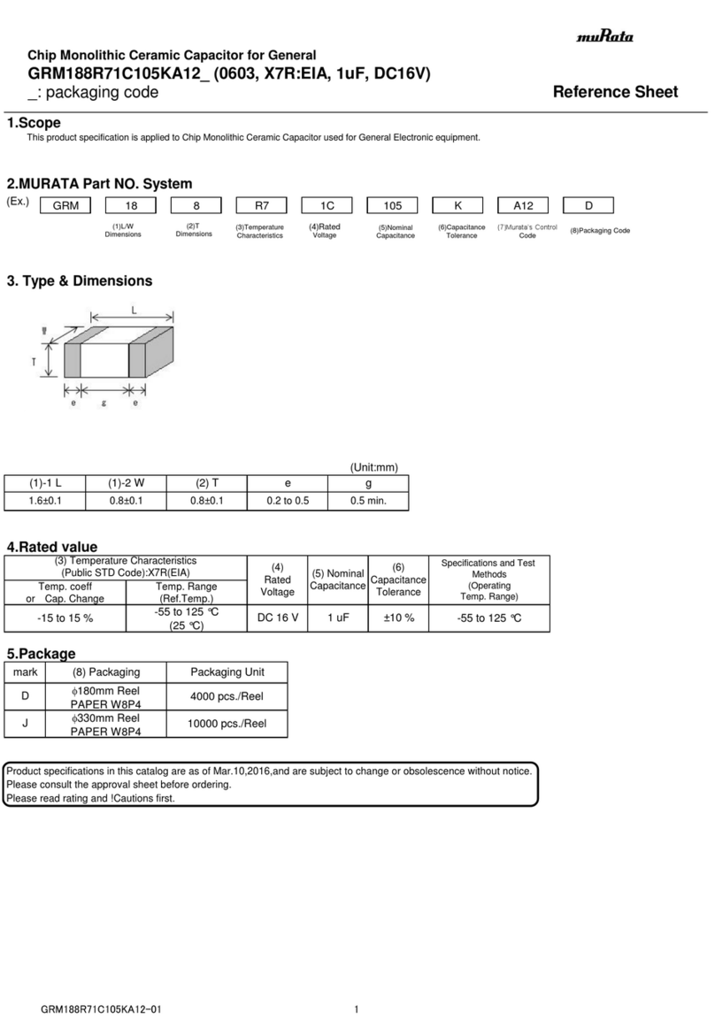
Murata GRM188R71C105KA12 Series Reference sheet
Akapp-Stemmann
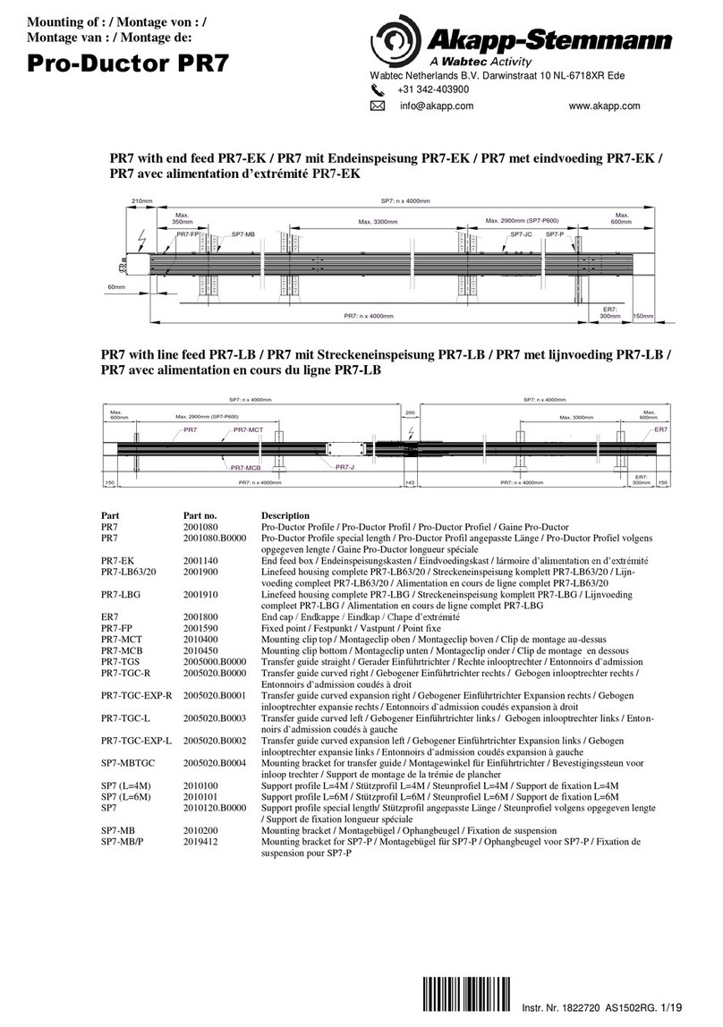
Akapp-Stemmann Pro-Ductor PR7 Mount Guide
Murata
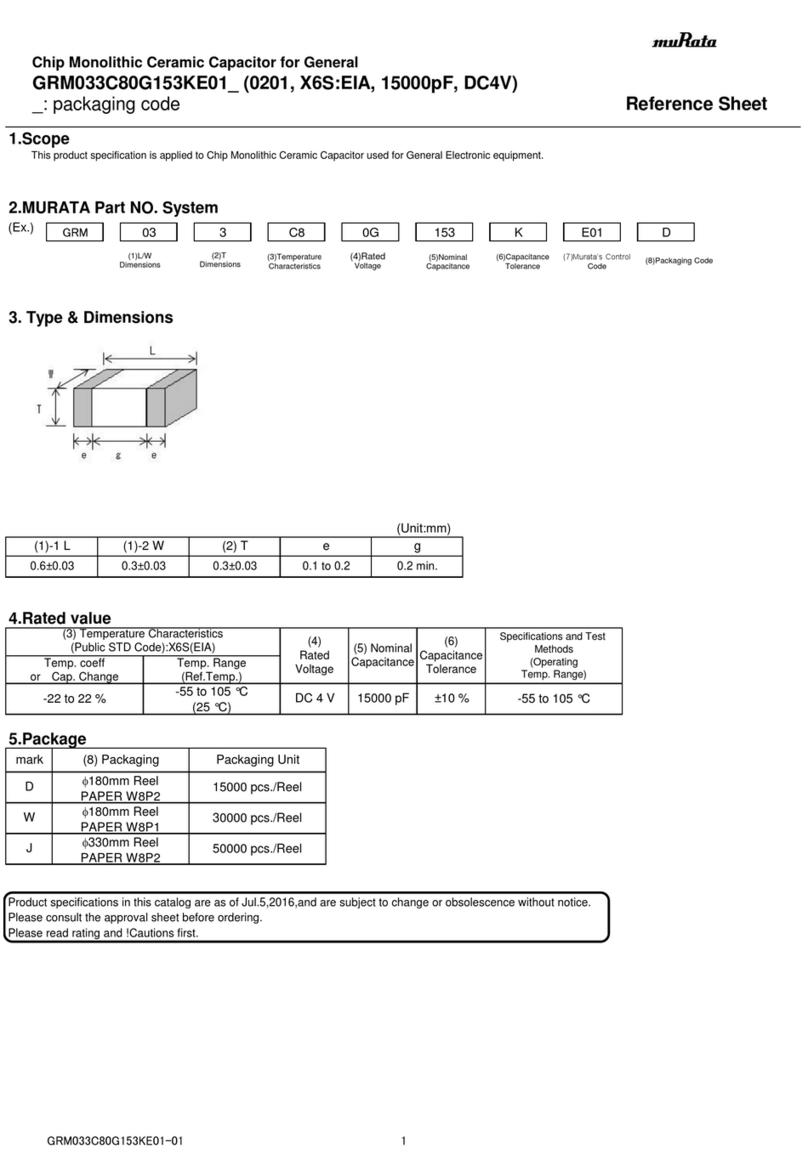
Murata GRM033C80G153KE01 Series Reference sheet
Murata
Murata GRM0225C1E1R4BA03 Series Reference sheet
Murata
Murata GRM185R61E105KA12 Series Reference sheet
ProSoft Technology
ProSoft Technology inRAx MVI46-N2 user manual
Murata
Murata GJM0335C1E3R6CB01 Series Reference sheet
Murata
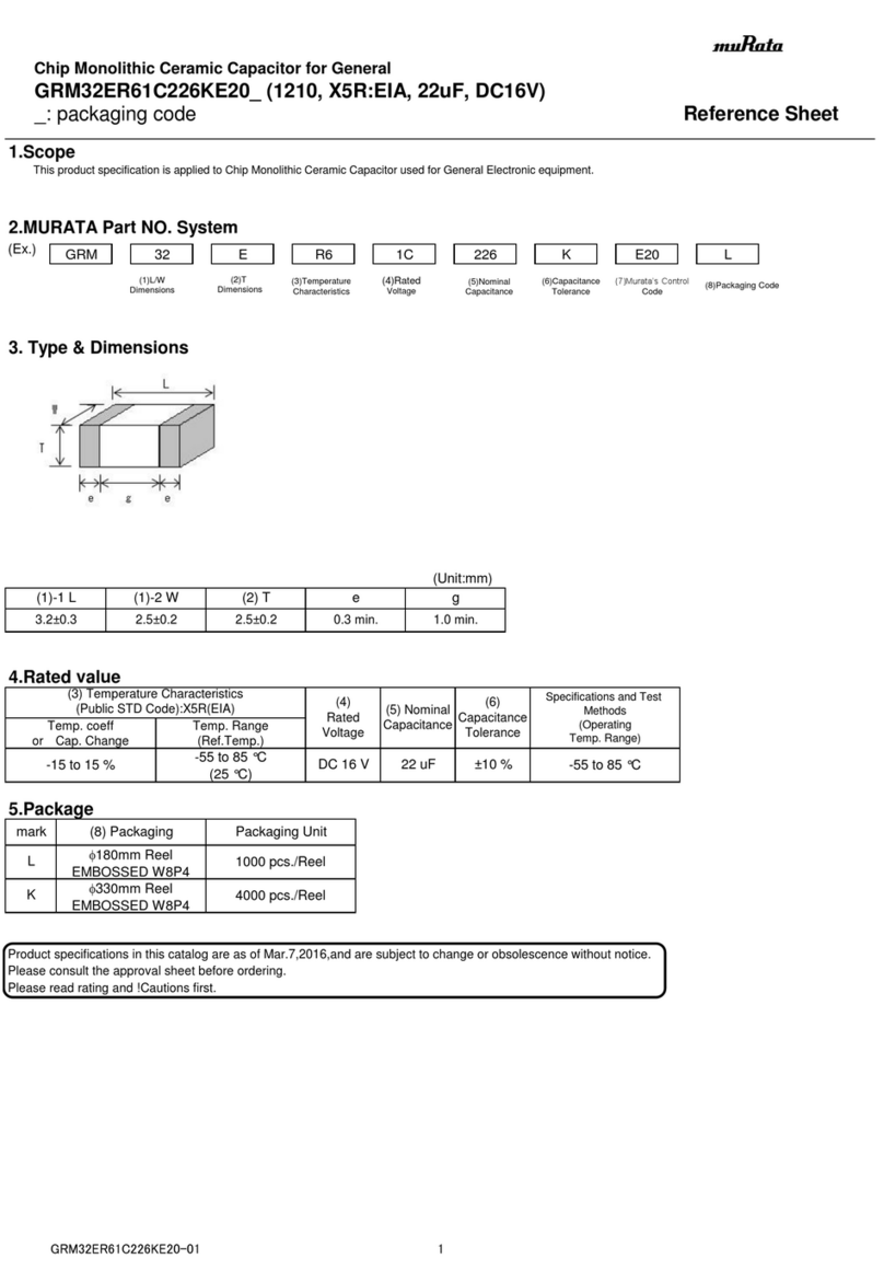
Murata GRM32ER61C226KE20 Series Reference sheet
Murata
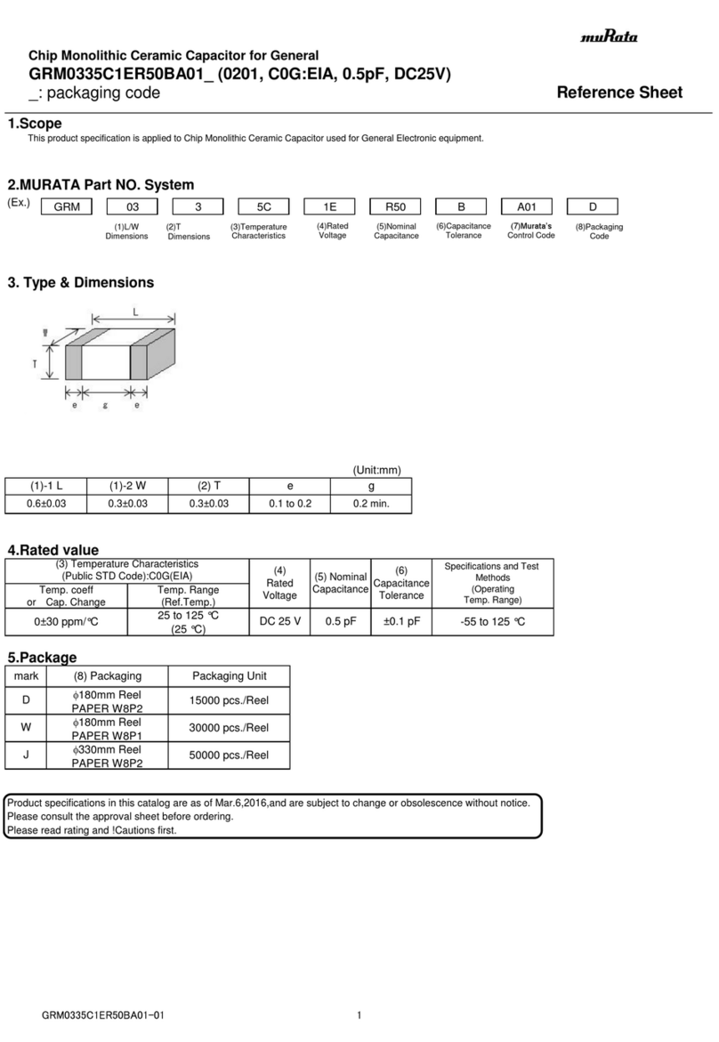
Murata GRM0335C1ER50BA01 Series Reference sheet

OEZ
OEZ CS-BH-A021 Instructions for use
