enware Custodian WMSSB-000 User manual
I00348_Jun 20
Installation and Maintenance Instructions
The Custodian
®
Smart Board
Call 1300 369 273
www.enware.com.au
Enware Australia Pty Limited
9 Endeavour Rd Caringbah NSW 2229 Australia
Ph: 02 8536 4000 info@enware.com.au
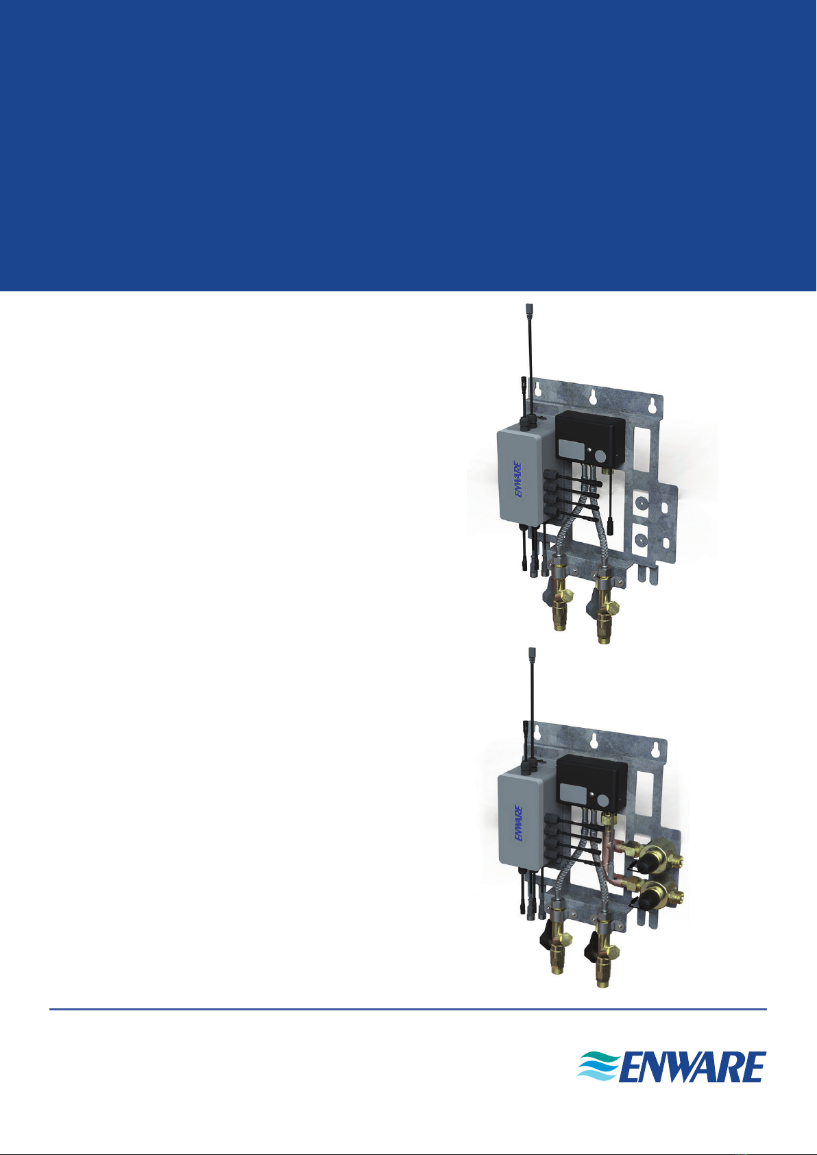
WMSSB-000 - without solenoids
WMSSB-001 - with solenoids

2 Call 1300 369 273 www.enware.com.au
product description
The Custodian®Smart Board directly controls and monitors the delivery of water in secure or
controlled bathroom environments. The compact and easy to install unit houses the Electronic
Thermostatic Mixing Valve (eTMV), eTMV Control Hub (WMSSB-000 model), with Basin/
Shower solenoids and service isolation/strainers and check valves (WMSSB-001 model).
Features:
• Rapid installation of pre-assembled and tested plumbing assembly
• Integrated control of water flow and thermostatic temperature control of shower and basin
• Toilet full and half flush connections
• Plug-and-play cable connectors for all fixtures and Smartflow Water Management System
The eTMV Control Hub is designed to be a generic smart hardware platform which is used for
multiple applications such as shower and basin tapware and toilet flush valves in domestic /
public / aged care / hospital / detention plumbing systems depending on the configuration.
The hub has a RS485 network interface to connect to either a local or cloud based water
management system. The network connection allows the hub to be configured, monitored
and updated remotely.
When activated, water is delivered to the shower or basin outlet at the selected thermostatic
temperature and for a pre-configured runtime. This is achieved by using an Electronic
Thermostatic Mixing Valve (eTMV) for temperature control and a solenoid for flow control. The
available activation methods depend on the configured mode.
www.enware.com.au Call 1300 369 27 3
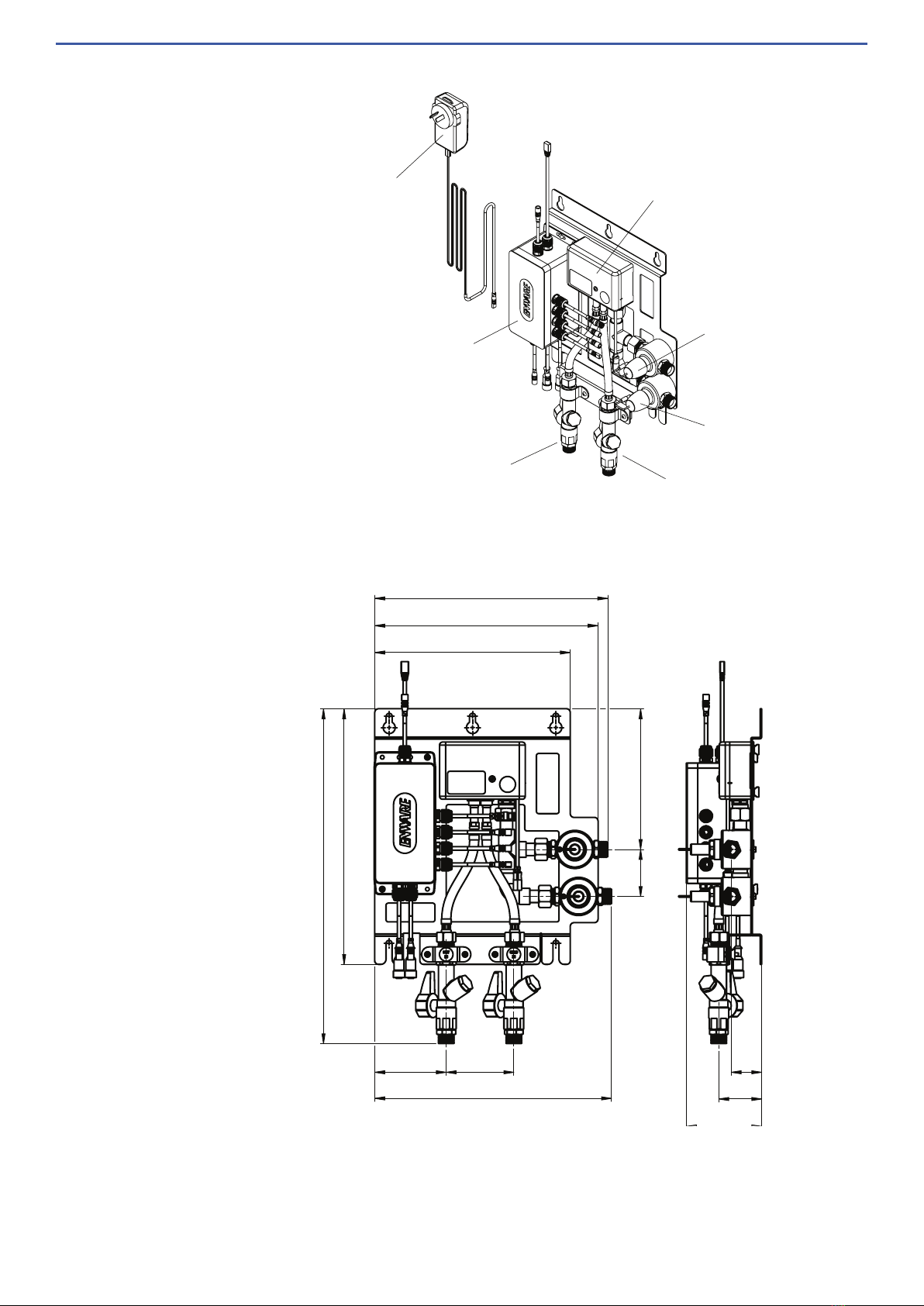
260
340
445
297
310
95
315
187
63
90
100
57
41
SOLENOID
MIXED TO SHOWE
R
SOLENOID
MIXED TO BASIN
HOT INLET
ISOLATION, STRAINER
& CHECK VALVE COLD INLET
ISOLATION, STRAINER
& CHECK VALVE
ETMV
CONTROL HUB
ELECTRONIC TMV
TRANSFORMER
12V DC
All measurements are in millimetres.
The Custodian®Smart Board
(WMSSB-001 Model)
(WMSSB-001 Model)
4 Call 1300 369 273 www.enware.com.au
technical data - electronic tmv
Water Supply
Inlet Temperatures Cold: Min. 5°C Max. 30°C
Hot: Min. 55°C Max. 85 °C
Outlet Temperature Range
(Temperature limits and sengs controlled by
Smarlow System)
Min. 5 °C Max. 50 °C (+/- 2˚C)
Thermal Flush Temperature
(Temprorarily enabled by server, acvated on site)
Max. 70 °C
Dynamic Inlet Pressures Min. 100 kPa Max. 500 kPa
Dynamic Pressure Dierenal
Between Hot and Cold Supplies
Must be less than 100 kPa*
Stac Inlet Pressure
For Tesng Purposes / System Commissioning
Max. 1600kPa
Minimum Flow Rate 2 Litres/min
Maximum Flow Rate 32 Litres/min @ 300 kPa pressure loss
as per ow sizing graph
Inlet & Outlet Connecons 1/2" BSP Male
*AS3500.4 clause 1.9.4.2 - The dynamic pressure differential between hot and cold supplies when
mixed at a thermostatic mixing valve shall not exceed 10%.
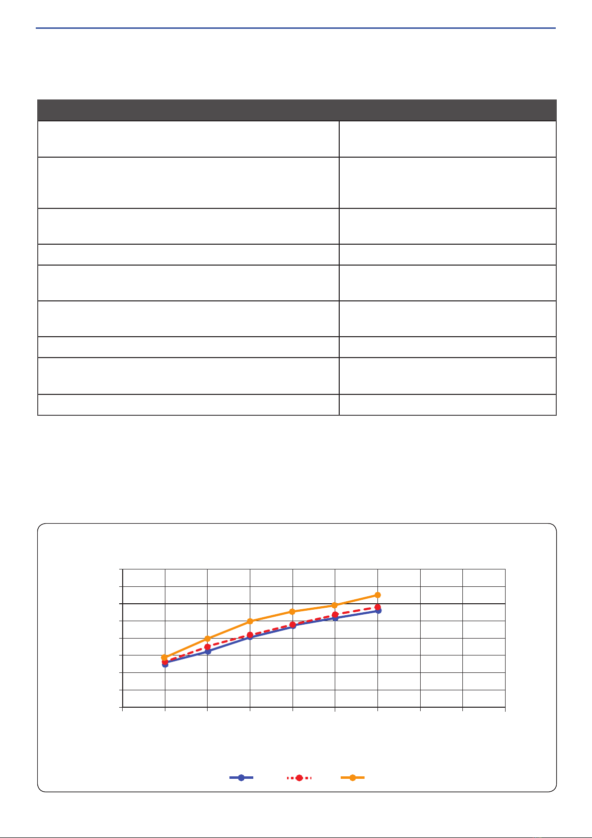
Electronic Thermostatic Mixing Valve (eTMV)
eTMV Flow Sizing Graph
FLOW RATE VS PRESSURE LOSS
40
35
30
25
20
15
10
5
0
050 100 150 200 250 300 350 400
450
Flow rate ( litres / minute )
Dynamic pressure (kPa)
cold hot mixed

www.enware.com.au Call 1300 369 27 5
Power
Included Power Supply Input Requirements 100-240VAC 50/60Hz
Nominal Input Voltage 12VDC
Input Voltage Tolerance 10%
Typical Power Consumpon 1W
Maximum Power Consumpon 36W
Environmental Specicaons
Heat Output (BTU/HR) 3.4
Operang Temperature 5 - 50 °C
Communicaon Ports
Type of Port Smarlow Communicaon Port
Number of Connectors 1
Serial Port Protocol RS485
Serial Port Speed 38400 baud
Piezo Buon Ports
Number of Inputs 4
Type of Inputs Piezo Buons
Number of Connectors 2
Type of Connector KCC SK5/5 Male
TLI Control Wheel Port
Number of Connectors 2
Type of Connector KCC SK9/8 Male
Flushing Solenoid Ports
Number of Outputs 1
Type of Outputs 10W solenoid
Voltage of Outputs 12V
Number of Connectors 1
Connector Type KCC SK2/2 Female
eTMV Control Hub
technical data - eTMV control hub

6 Call 1300 369 273 www.enware.com.au
installation
1. The Custodian®Smart Board should be
securely fixed to a wall in close proximity
to the interface facia plate(s), flushing
solenoid, and within 1m of a 240VAC
GPO ideally located above the Smart
Board.
It should be placed in a clean dry
environment, in an access duct or service
duct or some other appropriate location
where it can be accessed for servicing.
Fix Smart Board to a wall, using
appropriate screws. SEE IMAGE 01
Enware products are to be installed in accordance with the Plumbing Code of Australia (PCA)
and AS/NZS3500. Installations not complying with PCA and AS/NZS 3500 may void the
product and performance warranty provisions.
Reference should also be made to the Australasian Health Facility Guidelines (AHFG), ABCB
and Local Government regulations when considering the choice of, and the installation of
these products.
NOTE: Enware Australia advises:
1. Due to ongoing Research and Development, specifications may change without notice.
2. Component specifications may change on some export models.
For use with potable water only.
installation compliance
IMAGE 01
www.enware.com.au Call 1300 369 27 7
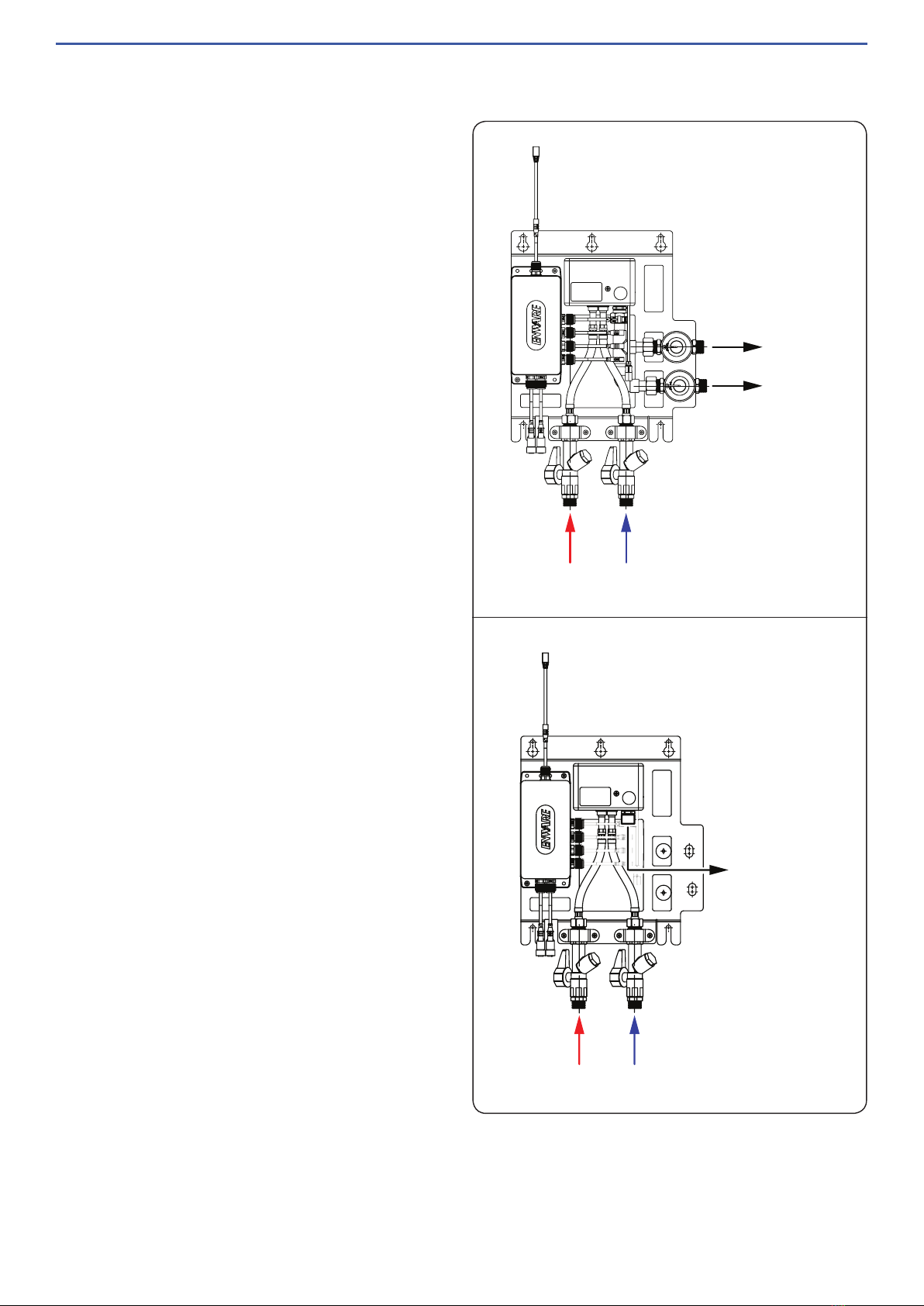
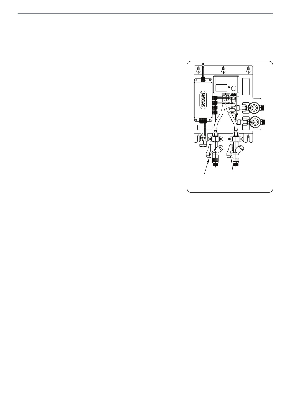
2. Flush water supply lines and ensure the
lines are clear of any debris.
3. Connect water lines to each connection.
SEE IMAGE 02
CONNECTION TO SHOWER
CONNECTION TO BASIN
COLD INLET
1/2” BSP MALE
HOT INLET
1/2” BSP MALE
IMAGE 02
ETMV OUTLET
CONNECTION
COLD INLET
1/2” BSP MALE
HOT INLET
1/2” BSP MALE
WMSSB-001 Model
WMSSB-000 Model
www.enware.com.au Call 1300 369 27 8
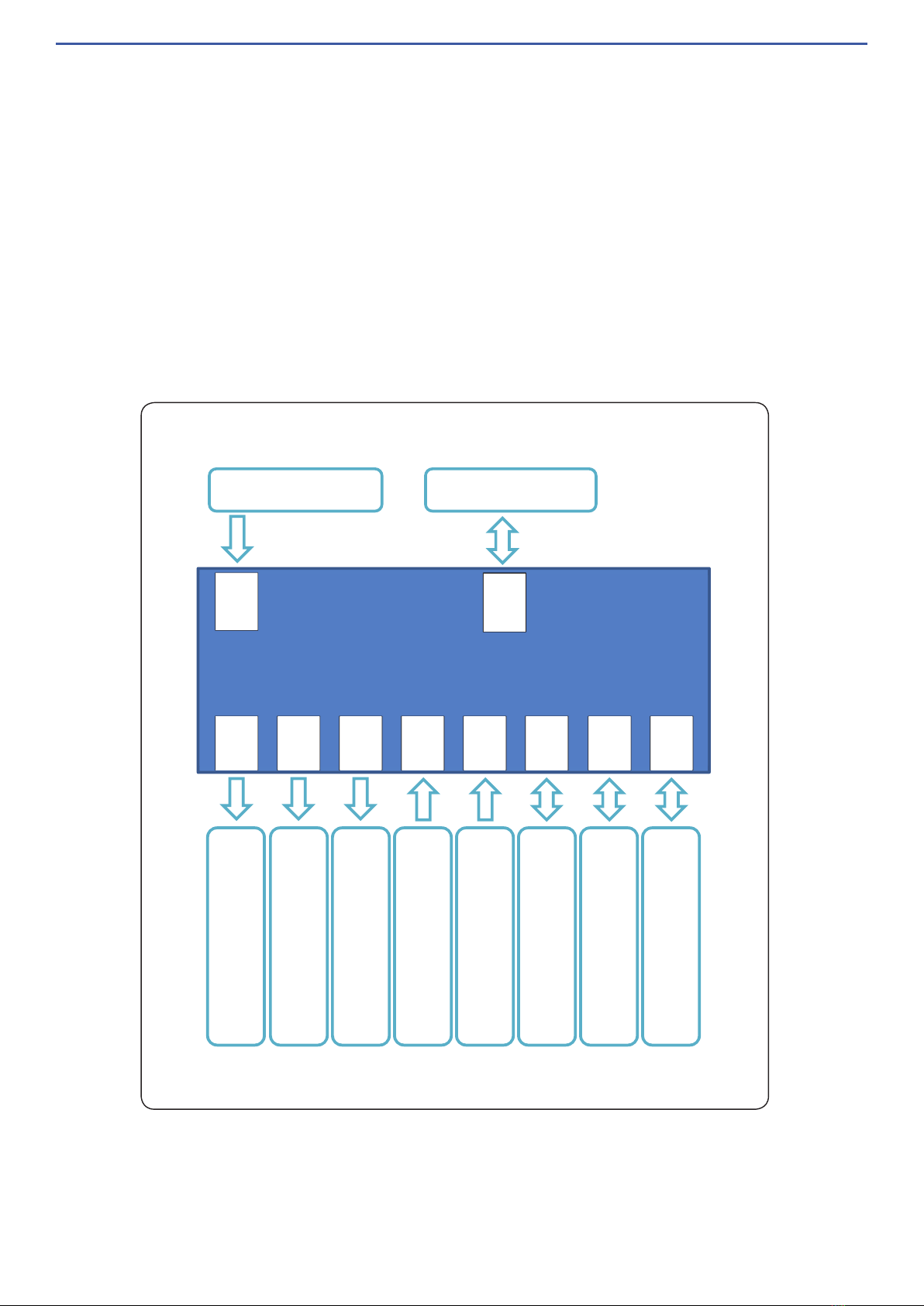
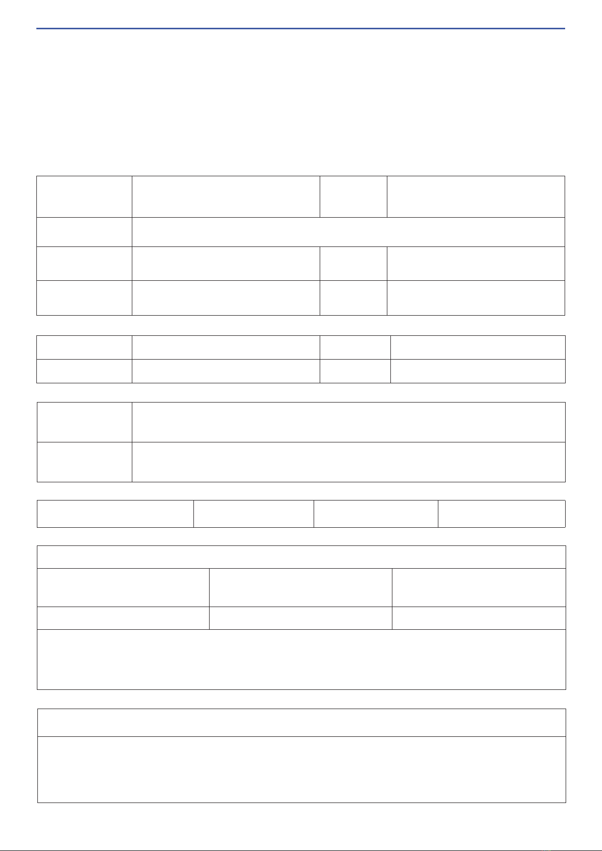
Control Hub Overview
SN3SN2SN1ETMV
12V
DC
RS485
B1,B2
TLI1
TLI3
B3,B4
eTMV Control Hub Cable Connections
1. Connect cable connections for the control plate(s) and flushing solenoid to eTMV Control
Hub.
The cable connections should be plugged into the eTMV Control Hub in the location
marked with the same designator - e.g. “w1” should be connected to the other cable
labeled “w1”.
Care should be taken with the position and orientation of the connections. Align white
marking on the connectors when connecting. When unplugging cables, hold the cable
connectors themselves, and do not pull on the cables.
Follow the installation instructions for eTMV Control Panel for correct cable connections.
2. Connect RJ45 Network cable to the surface mount RJ45 Jack.
The main Backbone Cable will have already been installed and a surface mount RJ45
Jack will be fitted less than 1m above the Custodian Smart Board location.
3. Finally connect the power supply (supplied transformer) to power the Custodian®Smart
Board.
9 Call 1300 369 273 www.enware.com.au
eTMV Control Hub Connections
• 1x RJ45 network cable for communications and updates (external)
• 1x power supply input (external)
• 4x piezo button inputs (external)
• 2x TLI control wheels (external)
• 1x ETMV output (on Smart Board)
• 2x shower / basin solenoid outputs (on Smart Board)
• 1x flushing solenoid output (external)
ETMV CONTROL HUB
SHOWER SOLENOID
BASIN SOLENOID
FLUSH SOLENOID
SHOWER TLI
BASIN TLI
ETMV
SHOWER AND BASIN
ACTIVATION BUTTONS
FULL AND HALF FLUSH
BUTTONS
SN2
SN1
SN3
B1,B2
B3,B4
W1
W3
ETMV
Smart Flow RS485
RS485
12VDC
12V POWER PACK

10 Call 1300 369 273 www.enware.com.au
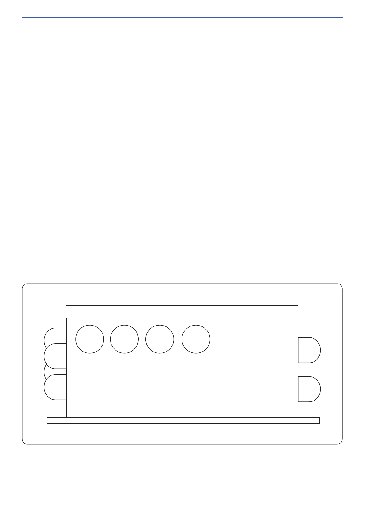
operation
Piezo Button Activation
WC HALF FLUSH
ACTIVATION
WC FULL FLUSH
ACTIVATION
BASIN OUTLET
ACTIVATION
SHOWER
ACTIVATION
PRESS ONCE TO ACTIVATE
CONTROL PANEL
IMAGE 03
Lightly press the piezo button once to activate. SEE IMAGE 03
www.enware.com.au Call 1300 369 27 11
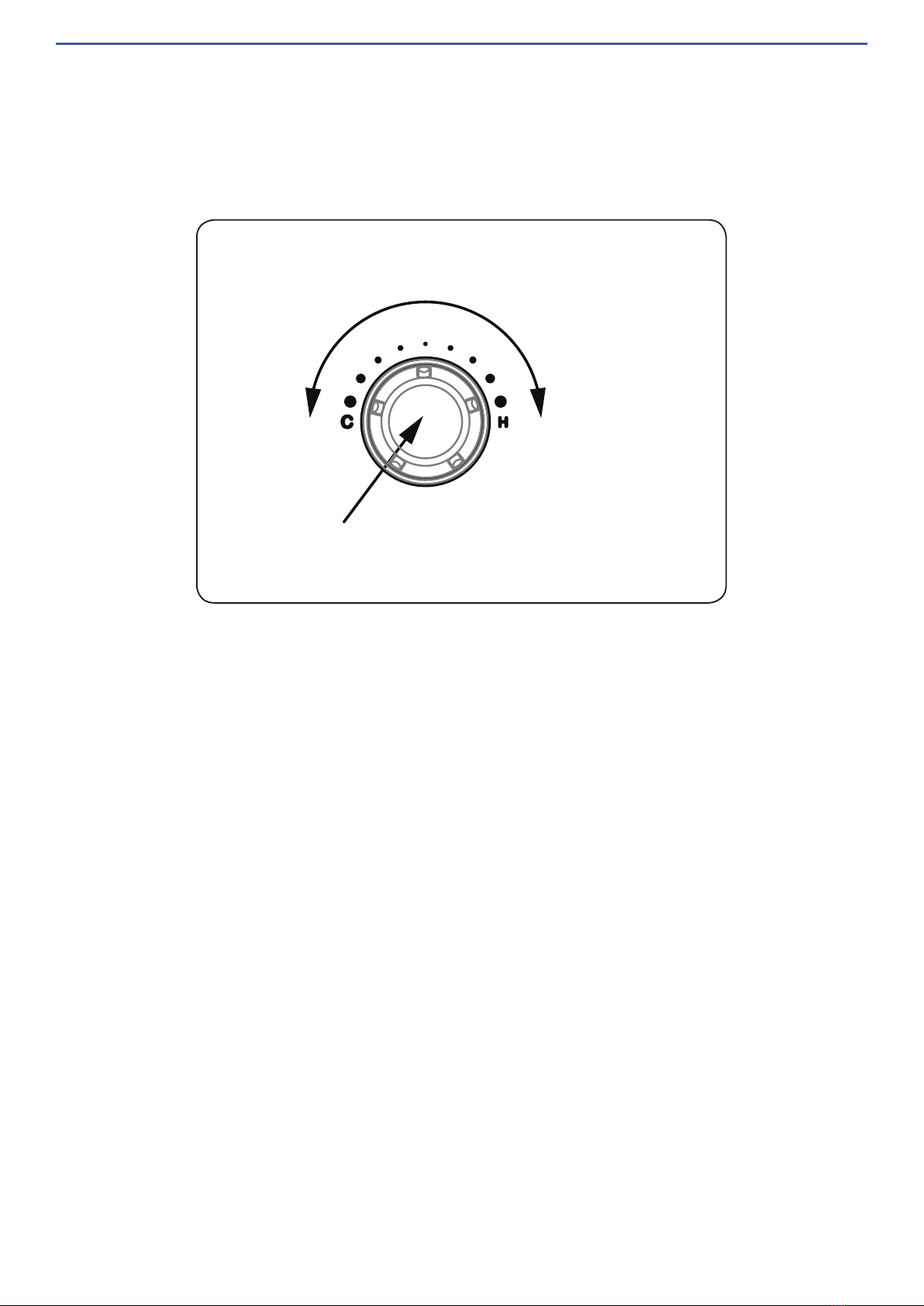
The temperature control wheel activation button (TLI) adjusts the temperature of water
delivered to shower or basin, and is also a push activation button for shower or basin
(depending on the configuration).
The lights in the TLI are used to provide feedback to the user on the current operating state.
When activated the TLI colour will change from blue to orange to red as the temperature set
point is adjusted from cold to warm to hot.
TLI Wheel Light Indicators:
• Time Pulse: A number of pulses proportional to the number of minutes the shower
has been running will take place periodically. The time between each set of pulses is
configurable.
• Eco Pulse: The TLI will pulse green, orange or red depending on how long the shower has
been running. The time between each set of pulses is configurable.
• End Flash: The TLI will flash in the last few seconds of the shower.
• 30 Second Warning Flash: The TLI will flash a few times when there is 30s remaining.
Disabled if Time Pulse or Eco Pulse are enabled.
• Water Pulse: The water will turn off for 1s then back on when it reaches the pre-set time
remainder time before the shower turns off automatically.
• When Disabled: if the user attempts to use a disabled interface it will flash pink 4 times on
all TLI control wheels.
TURN TO ADJUST TEMPERATURE
+
-
PUSH TO ACTIVATE SHOWER / BASIN TAP*
* FOR SELECTED MODELS WITH NO PIEZO BUTTON ACTIVATION
BLUE
ORANGE
RED
°C
°C
Temperature Control Wheel and Activation Button (TLI)
IMAGE 04
Push the wheel button once to activate.*
Turn the wheel to adjust outlet temperature.

12 Call 1300 369 273 www.enware.com.au
commissioning - eTMV
Upon completion of the installation, the valve should be tested and commissioned as per the
procedure outlined below or as specified by the local authority.
A calibrated digital thermometer having rapid response time with maximum temperature
hold will be required to measure the outlet mixed temperature of the valve. (Enware Code
ATMS1200 - Aquablend Test Kit)
1. Check the Outlet Temperature
1. Open the cold supply line to eTMV, then open the hot supply line, ensuring there are no
leaks.
2. Activate and open the outlet that is serviced by the shortest length of pipework between
the mixing valve and outlet fixture. To do this, press the piezo button or Temperature
Control Wheel on the Fascia Control Plate to activate shower or basin tap.
(The default maximum run time per activation is 2 minutes for basin and 45 minutes for
shower.)
3. Turn the Temperature Control Wheel clockwise to the highest warm water temperature
setting.
4. Allow the mixed outlet to flow for at least 60 seconds to allow the temperature to stabilize,
then take a temperature reading at the outlet with a digital thermometer.
The flow rate should be at least 2L/min. The flow rate can be checked with the aid of a
known size container and a stopwatch.
5. Activate the other outlet (if applicable) while the first one is running. Check that the outlet
temperature is stable over the full range of flow rates, and that the temperature and flow
rate is adequate for the application.
www.enware.com.au Call 1300 369 27 13
HOT ISOLATION
VALVE
COLD ISOLATION
VALVE
2. Shut Down Test
Now that the temperature has been checked, it is
necessary to perform a shut down test.
1. Turn on the outlet and turn the Temperature
Control Wheel clockwise to the highest warm
water temperature setting. Allow the mixed water
temperature to stabilise and note the outlet
temperature.
2. While holding a digital thermometer in the outlet flow,
quickly isolate the cold water supply to the valve by
shutting the cold water inlet isolation valve.
(SEE IMAGE 05)
The outlet flow should quickly cease flowing. The flow
should be less than 0.1L/min following the isolation.
Monitor the maximum outlet flow temperature,
and record this on the Commissioning Report. The
temperature should not exceed that allowed by the
applicable standard or code of practice for each
state.
3. Restore the cold water supply to the valve. After
the mixed water temperature has stabilised, note
the outlet temperature again, ensuring the outlet
temperature has re-established.
4. Repeat the above test, except this time quickly isolate the hot water supply to the valve by
shutting the hot water inlet isolation valve. The outlet flow should quickly slow to a trickle.
The trickle should be less than 0.1L/min following the isolation.
5. Restore the hot water supply to the valve. After the mixed water temperature has
stabilised, measure and record the outlet temperature, ensuring the outlet temperature has
re-established.
6. Turn off the outlets.
Ensure that all details of the Commissioning Report are completed and signed by the relevant
signatories, and a copy is kept with the installer and owner of the premises.
The valve is now commissioned and it can be used within the technical limits of
operation.
IMAGE 05

14 Call 1300 369 273 www.enware.com.au
Commissioning Mode - Explanation
Once installed and commissioned the Custodian®Smart Board can operate as an
independent device in Commissioning Mode. The operation and control of the fixtures will be
determined by the firmware in the eTMV Control Hub.
Commissioning Mode allows for the automatic flushing of pipes, especially during
commissioning phase or for rooms with an extended vacancy.
Commissioning Mode is enabled by default (for Custodian®devices only) and eTMV Control
Hub will operate in this mode until commissioning mode is manually disabled or the firmware
is changed. This can be achieved via the software operating on the central control PC via
the main Backbone Network Cable, or by a standalone laptop connected directly to the
Custodian®eTMV Control Hub.
Manager Activation
It can be enabled or disabled using the Smart Flow Software or manually by unscrewing the
lid and pressing the blue button quickly 3 times.
Data Logging
Temperature and flow is recorded.
Sequence
The following sequence will occur at a random time (to prevent all hubs running
simultaneously) if Commissioning Mode is enabled:
1. T=0m 00s: TLIs start flashing orange, wait 10 seconds
2. T=0m 10s: Shower runs at 40°C for 30 seconds
3. T=0m 40s: Shower stops, wait 3 seconds
4. T=0m 43s: Shower runs at 15°C for 10 seconds
5. T=0m 53s: Shower stops, wait 3 seconds
6. T=0m 56s: Basin runs at 40°Cfor 30 seconds
7. T=1m 26s: Basin stops, wait 3 seconds
8. T=1m 29s: Basin runs at 15°C for 10 seconds
9. T=1m 39s: Basin stops, wait 3 seconds
10. T=1m 42s: Toilet runs for 3 seconds
11. T=1m 45s: Toilet stops, TLIs return to flashing white

www.enware.com.au Call 1300 369 27 15
maintenance and servicing - eTMV
The eTMV is a compact Thermostatic Mixing Valve that uses modern self-controlling
multiprocessor technology to monitor and control the temperature and flow, by means of
ceramic discs and electromechanical drives.
eTMV does not have a thermostatic wax element or dynamic O-rings that are typically
used in traditional thermostatic mixing valves. Instead, ceramic discs are controlled by
electromechanical drives, and eTMV has no parts to service or replace during regular
servicing.
The eTMV is constantly monitored for real-time performance by the Enware Smartflow TMV
monitoring system.
The eTMV will only require minimal preventative maintenance work to ensure it operates at
its optimum level of performance. The valve should be commissioned, and serviced annually,
unless the installed conditions dictate more frequent servicing is necessary.
Every 12 months eTMV should be inspected and tested. The valve and surrounding area
should be inspected for leaks or water damage and action taken if required. Ensure a clean
dry work area is available.
Servicing of eTMV is in line with AS4032.3.
Cleaning the Strainers
Firstly isolate the hot and cold supplies
to the mixing valve by closing the inlet
isolation valves. With a suitable spanner
remove strainer cap on the inlet fitting then
remove mesh strainer.
Clean strainers with a suitable descaling
solvent (such as CLR) diluted with water.
Check for physical damage and thoroughly
rinse with clean water. Strainers can then
be re-installed into the ball valve and
strainer cap replaced and tightened to a
maximum torque of 15Nm into the inlet ball
valve bodies.
Non-Return Valve Operation
To check Non-Return Valve on the HOT
inlet side, carry out the following steps:
annual maintenance procedure
CHECK VALVE
STRAINER
ISOLATION
STRAINER CAP
IMAGE 06

16 Call 1300 369 273 www.enware.com.au
5-year maintenance
The eTMV has no mechanical or electronic actuation component to service or replace at
regular servicing, and there are no parts to service or replace at 12-month or 5-year intervals
as described in the Australian Standard AS4032.3 Section B 4.2 and Section 2.7.1.
No replacement of thermostat or o-rings is required as the eTMV does not have any.
The 5-year maintenance will simply be an annual service. Refer to annual maintenance
procedure on page 15.
1. Turn OFF the isolation valve on the HOT inlet only (COLD inlet must be open).
2. Unscrew and remove Strainer Cap on the HOT side. SEE IMAGE 06
After releasing water pressure initially, observe any water leaking through the strainer.
3. If water continues leaking through this may indicate a fouled or faulty Non-Return Valve. If
this is the case, inspect the non-return valve for damage or any debris. Clean or replace
the combination ball valve if necessary.
If water does not leak through, this indicates the check valve is working correctly.
4. Re-install Strainer Cap.
5. Turn back ON the isolation tap on the HOT inlet.
6. To check Non-Return Valve on the COLD inlet side, repeat the above steps using the
COLD inlet side.
Check that the strainer caps are tight, and that there is no evidence of water leakage.
Recommissining and Shut Down Test
The valve must then be recommissioned as per instructions on page 12, including
temperature adjustment and shut down test.
If the valve fails to shut down or fails to maintain its set temperature, refer to Troubleshooting
on page 19.
Enware products should be cleaned with a soft damp cloth using only mild liquid
detergent or soap and water. Do not use cleaning agents containing a corrosive acid,
scouring agent or solvent chemicals. Do not use cream cleaners, as they are abrasive.
Use of unsuitable cleaning agents may damage the surface. Any damage caused in this
way will not be covered by warranty.
cleaning

www.enware.com.au Call 1300 369 27 17
thermal flush procedure
Thermal Flush feature in eTMV allows the facility’s maintenance team or licensed service
contactors to perform a controlled thermal flush to the eTMV and warm water plumbing
system. (Note: The thermal flush procedure is optional and does not form part of
commissioning and service requirements set out in AS4032.3.)
Before commencing the thermal flush, a site-specific procedure must be implemented to
control the risk of scalding. Hot water will run directly to the outlets fed by the Electronic
Thermostatic Mixing Valve, and precautions shall be taken to prevent the chance of injury.
Note: full temperature hot water will flow from the tapware. Care must be taken
to prevent scalding.
Manager Activation
It can be enabled or disabled using the Smart Flow Software, or by unscrewing the lid of
Control Hub and pressing the blue button quickly 15 times.
Data Logging
Temperature and flow is recorded.
Thermal Flush Sequence
1. When Thermal Flush is enabled through Smart Flow Software, the temperature control
wheels (TLI) will start flashing red and white. Note this will automatically disable after 3
minutes if left in this state.
2. Within 3 minutes, press a TLI button for 10 seconds until it begins rapidly flashing red. (If
there are multiple TLI's, only one of them needs to be pressed.)
3. Within 5 seconds, press the TLI button once. A slow, red flashing will start.
4. After 3 seconds, the shower and basin solenoids will open simultaneously and the eTMV
will run for 3 seconds at 15°C.
5. Next, eTMV will allow full hot water to pass through the eTMV and solenoids for 1 minute
to allow the temperature to stabilise.
6. It will then run for 5 minutes at 70°C or 10 minutes at 60-70°C.
7. The eTMV will deliver cold water for 30 seconds. The TLI’s will pulse blue during this
period.
8. The water stops and the TLIs will flash white 3 times if the thermal flush was a success. If
there is any issue with the system during this process (e.g. it didn’t achieve the minimum
60°C temperature) then the TLI with flash orange to show there was an error that needs
investigating.
9. The thermal flush process can be stopped at any time by pressing a TLI button, which will
send the system back to step 1.
18 Call 1300 369 273 www.enware.com.au
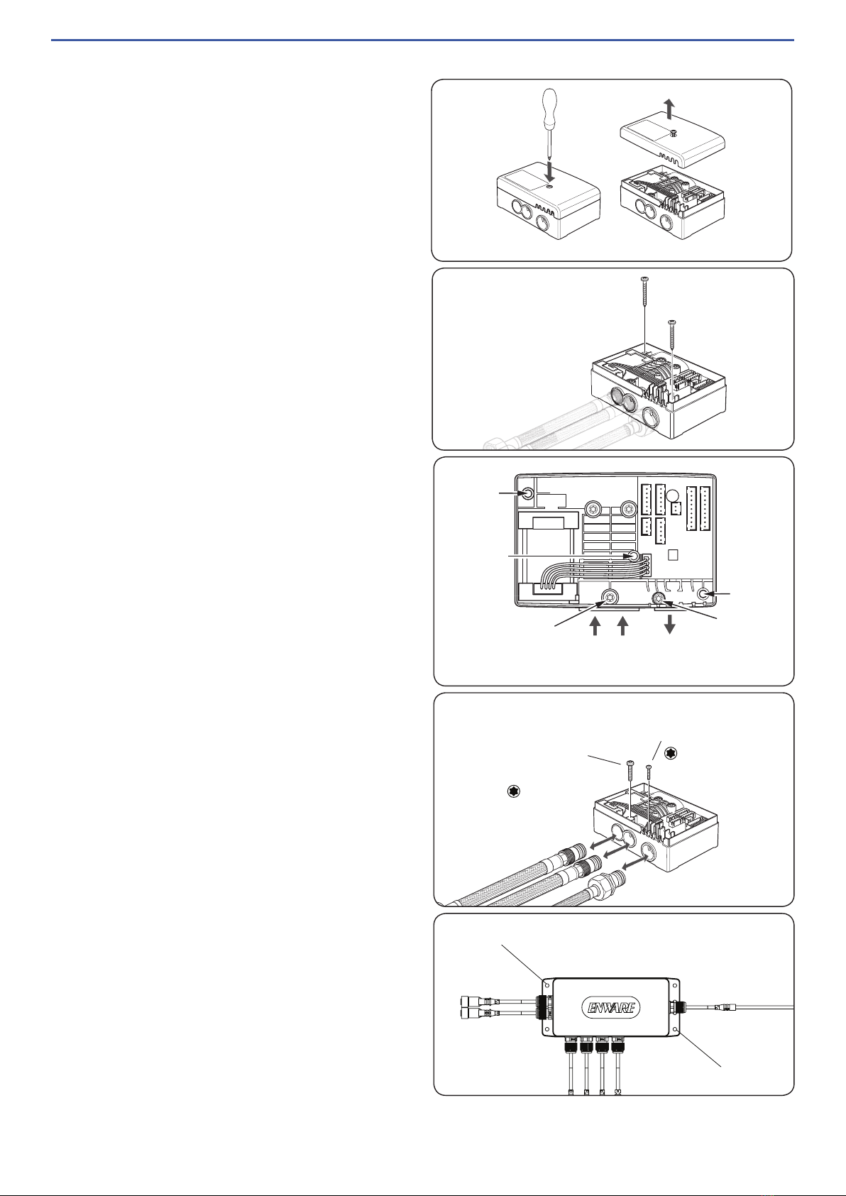
access to components
Replacing eTMV
1. Unscrew cover of eTMV.
SEE IMAGE 07
2. Loosen 2 screws holding eTMV to board
and keep at hand.
SEE IMAGE 09
3. Unplug eTMV cable. When unplugging
cables, hold the connectors, do not pull
on the cables to unplug.
4. Unscrew 2 fixing screws holding the inlet
and outlet adaptors.
SEE IMAGE 09 & 10
5. Once eTMV is loose, pull up the eTMV to
release it from water connections.
SEE IMAGE 10
To connect new eTMV to water connections,
align inlets and slowly but firmly push eTMV
into position. SEE IMAGE 10
Take cover off. Fix eTMV to board with the 2
screws that was taken in step 2.
Fit 2 screws taken in step 3 to lock the water
inlet adaptors in place. Re-fit cover.
When reconnecting cables, align the white
marking on the connectors to ensure correct
orientation.
Commission eTMV, by following the
commissioning procedure on page 12.
LOCKING SCREW
FOR INLET FITTING
LOCKING SCREW
FOR OUTLET FITTING
TORX T20
TORX T10
Replacing eTMV Control Hub
1. Unscrew 2 screws holding the Control
Hub. SEE IMAGE 11
2. Unplug cables. When unplugging cables,
hold the connectors and do not pull on
the cables to avoid damage.
3. Replace eTMV Control Hub with a new
one.
FIXING SCREW
FIXING SCREW
OutletHot Cold
Inlets
Fixing screw
hole
Fixing screw
hole
Cover retaining
screw hole
Inlet tting
locking screw
Outlet tting
locking screw
IMAGE 07
IMAGE 08
IMAGE 09
IMAGE 10
IMAGE 11

www.enware.com.au Call 1300 369 27 19
troubleshooting
spare parts
Name Part Code
Electronic TMV WMSSB-ETMV
Smart Board Hoses -
8mm x 1/2" BSP
(1 pair)
1/2” BSPM10 Male
200 WMSSB-HOSE
Solenoid - Basin /
Shower (each) ENMS207
FAULT / SYMPTOM CAUSE RECTIFICATION
1. Desired mix temperature
can’t be obtained / is diffi-
cult to set
* Supply water pressure is too
high
* Pressure differential between hot
and cold supplies are too high
* Flow rate is too high or too low
* Debris in line
* Temperature setting is too high /
too low
* Ensure water supplies are
within limits of the valve as
outlined in Technical Table on
page 4
* Check for debris in line and
clean
* Check system temperature
setting
2. Mixed water temperature
too hot or cold
3. Flow rate reduced or fluctu-
ating
4. eTMV is noisy
5. The valve will not shut down * Supply water temperature too
high or too low
* Ceramic disc in eTMV has failed
* Debris in line
* See Rectification 1
* Replace eTMV
6. Hot water flows into cold
water system or vice versa
* Check valve has failed
* Debris fouling check valve
Dismantle and clean / replace
combination inlet valve
7. Water leaks from outlet /
Water drips and does not
shut off
* Debris in line
* Supply water pressure too high
* Solenoid has failed
* See Rectification 1
* Check solenoid for debris
and clean. Replace solenoid
if required
8. Water is not flowing /
9. Poor water flow
* Aerator/ line is blocked by debris
* Water or power turned off
* eTMV has shut down
* Dismantle aerator or flow
control and clean
* Turn on power / water
* See Rectification 1
For further assistance, call Enware on 1300 369 273.
20 Call 1300 369 273 www.enware.com.au
Commissioning / Service Report for Thermostatic Mixing Valve
Name of
Establishment
(Name) Owner /
Occupier
(Name)
Street Address
Contact Name (Name) Phone
Date of Test Work
Order No.
Valve ID No. Model No.
Make of TMV Size
Valve location
/ Building
Area Serviced
by Valve
Number of Outlets Served Basin Shower Bath
Valve installed to requirements of
1. The local water supply
authority
2. The valve manufacturer /
supplier requirements
3. The Australian Standards
for Plumbing and Drainage
YES NO YES NO YES NO
If NO, give details and action taken:
Use a separate form for each valve.
The original report is to be retained on site for a minimum of 7 years.
Copies of the report shall be : provided to the owner/ occupier or the person responsible ; retained by the tester ; and
where required, forwarded to the relevant authority.
The test method is in accordance with AS4032.3 Appendix B.
Valve functioning in accordance with the application requirements: YES NO
If NO, give details and action taken:
This manual suits for next models
1
Popular Industrial Electrical manuals by other brands

Hotline
Hotline 47HLB150 Harrier Installation guide and warranty

Dallas Semiconductor
Dallas Semiconductor Maxim MAXQ3210 manual

Eaton
Eaton PKZM0-XDM12-PI Instruction leaflet

S&C
S&C PMH Series Operation

Murata
Murata GJM0335C1H1R2WB01 Series Reference sheet

Murata
Murata GRM21BR71A106ME51 Series Reference sheet


Burkert
Burkert AirLINE Ex 8650 quick start

Murata
Murata GRM033R70J122KA01 Series Reference sheet

Murata
Murata GRM0225C1E9R6CA03 Seris Reference sheet

Murata
Murata GRM0225C1E6R3BA03 Series Reference sheet

Murata
Murata GRM0225C1E9R9CA03 Series Reference sheet

Murata
Murata GRM0335C1E100JA01 Series Reference sheet